TE 2305570-1 User manual
Instruction Sheet
1 of 5
© 2018 TE Connectivity Ltd. family of companies.
All Rights Reserved.
*Trademark
TE Connectivity, TE connectivity (logo), and TE (logo) are trademarks. Other logos, product, and/or company names may be trademarks of their respective owners.
PRODUCT INFORMATION
1-800-522-6752
This controlled document is subject to change.
For latest revision and Regional Customer Service,
visit our website at www.te.com.
408-35037
01 MAR 18 Rev A
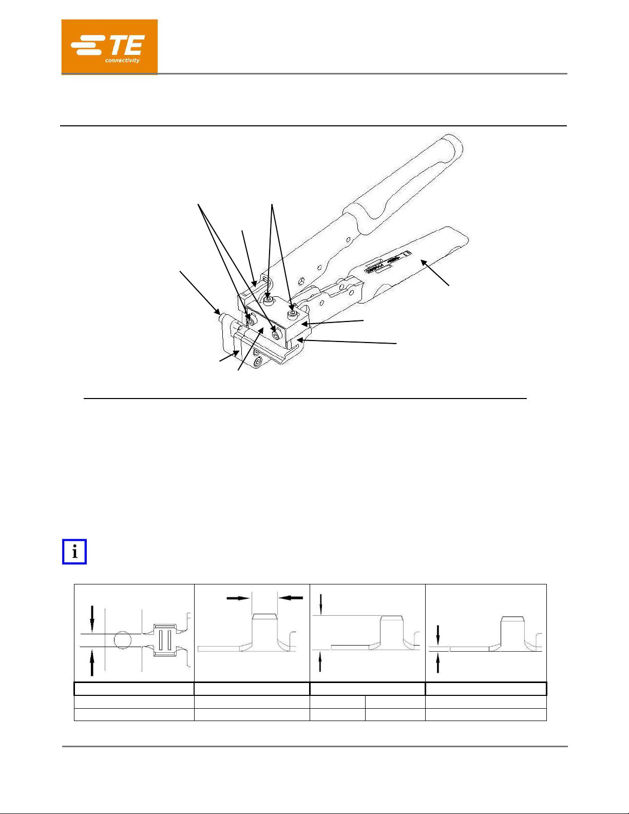
Figure 1
1. INTRODUCTION
The Light Duty Side Feed Terminal Cutter (PN 2305570-1) is designed to loose piece (cut) side-feed, front-
carrier terminals from the carrier strip.
2. DESCRIPTION
The tool is comprised of a Handle Assembly, Cut-off Anvil, Cut-off Shear, Strip Guide, Horizontal
Adjustment Block, Vertical Adjustment Plate, and Terminal Stop (reference Figure 1).
The tool adjustment specifications are presented in Figure 2.
NOTE
Dimensions in this Instruction Sheet are in inches [with millimeters in brackets]. Figures are not drawn to scale, but only for
reference.
Tab Width
Barrel Width
Barrel Height
Stock Thickness
(Max)
(Max)
(Min)
(Max)
(Max)
.130 [3.30]
.175 [4.45]
.050 [1.30]
.325 [8.30]
.024 [0.61]
Figure 2
PROPER USE GUIDELINES
Cumulative Trauma Disorders can result from the prolonged use of manually powered hand tools. Hand tools are intended for occasional use and low
volume applications. A wide selection of powered application equipment for extended-use, production operations is available.
Side Feed Terminal Cutter,
Light Duty, PN 2305570-1
Horizontal
Adjustment
Screws (2)
Cut-off
Shear
Terminal Stop
Handle
Assembly
Horizontal Adjustment Block
Strip Guide
Vertical Adjustment Plate
Cut-off Anvil
Vertical
Adjustment
Screws (2)

408-35037
Rev A
2 of 5
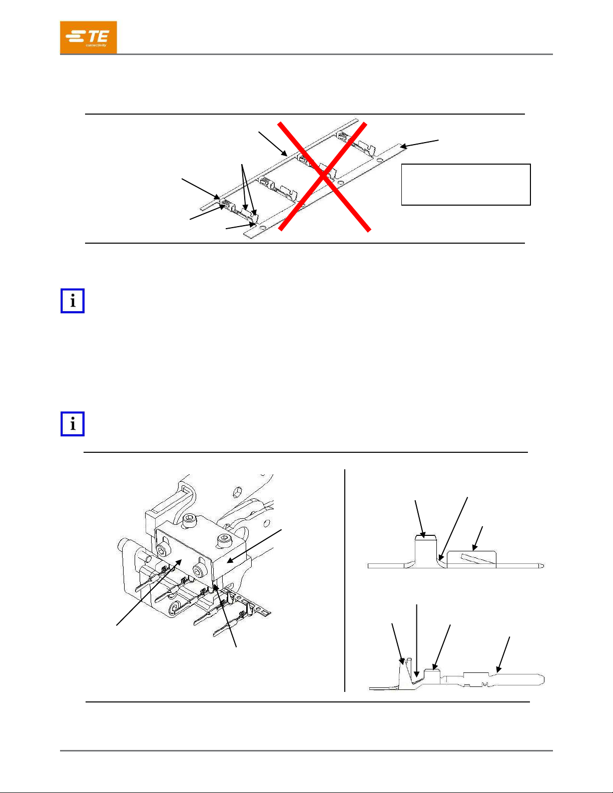
3. TERMINAL DESCRIPTION
NOTE
This tool is designed specifically to loose piece side-feed front-carrier terminals. Tool is not designed to loose piece end-
feed, center-carrier or dual-carrier terminals.
3.1. Side-Feed Front-Carrier Terminals
Terminal consisting of a contact body, crimp barrels, tab and single-carrier strip located adjacent to the crimp
barrels.
Figure 3
3.2. End-Feed Terminals
Terminal consisting of a contact body, crimp barrels and tab. The tab is located between the contact body
and crimp barrels of the next terminal in sequence.
Figure 4
3.3. Center-Carrier Terminals
Terminal consisting of a contact body, crimp barrels (or other style termination feature) and tab. The tab is
located between the contact bodies of the terminals.
Figure 5
Contact Body
Tab
Carrier Strip
Crimp Barrels
Contact Body
Crimp Barrels
Tab
Tab
Crimp Barrels (or Other
Style Termination Feature
Contact Body
This Style of Terminal
CANNOT
Be Used with the Cutter
This Style of Terminal
CANNOT
Be Used with the Cutter
408-35037
Rev A
3 of 5
3.4. Dual-Carrier Terminals
Terminal consisting of a contact body, crimp barrels, a tab and carrier strip adjacent to the crimp barrels of
the contact, and, a tab and carrier strip adjacent to the contact body portion of the contact.
Figure 6
4. ADJUSTMENT PROCEDURE [FIGURE 7]
NOTE
The adjustment procedure is performed most easily with a small strip of terminals - approximately 4 to 5.
1. Loosen the Vertical and Horizontal Adjustment Screws just enough to allow the Vertical Adjustment
Plate and Horizontal Adjustment Block to move.
2. Move the Vertical Adjustment Plate and Horizontal Adjustment Block so the terminal strip can be
inserted into the Strip Guide; positioning the contact barrel against the Strip Guide surface indicated
(see Figure 7).
3. Lower the Vertical Adjustment Plate into the transition area between the Insulation Barrel and the
Wire Barrel of the terminal.
NOTE
Some terminals do not have an Insulation Barrel –in that case, use the transition area between the Wire Barrel and the
Contact Body to set up the tool (see Figure 7; Contact Details).
Figure 7
Wire Barrel
Transition Area
Contact Body
Contact Body
Wire Barrel
Transition Area
Insulation
Barrel
Vertical
Adjustment
Plate
Locate Terminal Against
Strip Guide Surface
Horizontal
Adjustment
Block
Contact Details
Tab
Crimp Barrels
Contact Body
Tab
Carrier Strip
This Style of Terminal
CANNOT
Be Used with the Cutter
Carrier Strip

408-35037
Rev A
4 of 5
4. Rotate the tool in a vertical orientation.
a. Slide the Horizontal Adjustment Block towards the tool handles, allowing the Vertical Adjustment
Plate to rest on the appropriate crimp barrel.
b. Position the Vertical Adjustment Plate in the transition area of the terminal, allowing clearance
between the Vertical Adjustment Plate and the transition area to prevent the terminal from
binding in the tool.
c. Tighten the Vertical Adjustment Screws.
d. With the Vertical Adjustment Plate resting on the appropriate crimp barrel, tighten the Horizontal
Adjustment Screws.
CAUTION
Do not over-tighten any of the adjustment screws, as damage to the tool may occur.
Figure 8
5. Test the adjustments by sliding the terminal strip left and right. If the terminal strip is tight and does
not slide easily, loosen the Horizontal Adjustment Screws and slide the Horizontal Adjustment Block
towards the contact body to allow more clearance between the contact barrels and Strip Guide.
CAUTION
The terminal strip should have minimal clearance between the Insulation or Wire Barrel and the Strip Guide. Excessive
clearance may allow tab length to exceed the TE requirement for the specific terminal being cut.
Vertical Adjustment
Screws (2)
Allow Clearance Between
Vertical Adjustment Plate
and Transition Area
Allow Vertical Adjustment
Plate to Rest on Crimp Barrel
Horizontal
Adjustment
Screws (2)
408-35037
Rev A
5 of 5
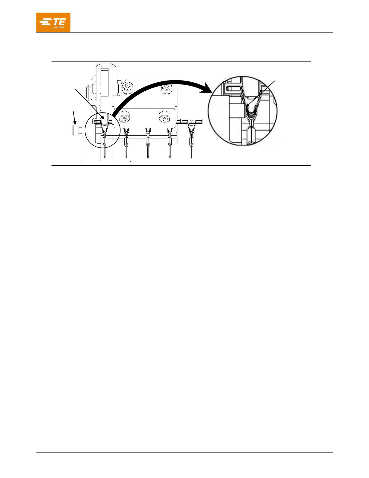
6. Slide the terminal strip into the tool until the terminal contacts the Terminal Stop.
Adjust the Terminal Stop to position the tab in the center of the Cut-off Shear (see Figure 9)
Figure 9
5. CUTTING PROCEDURE
1. Insert strip terminals into the Strip Guide until the Terminal Stop is reached.
2. Cycle the hand tool to shear the terminal from the carrier strip.
Measure the cut-off tab length to confirm it is within TE specification for the specific terminal being
cut. Note: If cut-off tab does not meet the TE specification, repeat set-up procedure in Section 4.
3. When cut-off tab length meets the TE requirement, advance terminal strip to position the next
terminal against Terminal Stop and cycle tool. Additional loose-piecing of terminals may commence.
6. TOOL MAINTENANCE AND INSPECTION
6.1. Maintenance
Remove any debris with a clean, soft brush. Ensure that the tool is clean by wiping it with a clean, soft
cloth. DO NOT clean with objects that could damage any components.
6.2. Visual Inspection
1. Inspect the tool on a regular basis to ensure excessive wear or any damage does not exist.
If damage or abnormal wear is evident, the tool must be replaced (refer to Section 7).
2. Inspect the Cut-off Anvil and Cut-off Shear for chipped, worn, or broken areas –if evident, refer to
Section 7.
7. REPLACEMENT
If the Cut-off Anvil and/or Cut-off Shear are damaged or worn excessively, the tool must be replaced. Order a
new tool through your TE representative; call 1-800-522-6752, send a facsimile of your purchase order to
717-986-7605, or write to:
CUSTOMER SERVICE (038-035)
TE CONNECTIVITY CORPORATION
PO BOX 3608
HARRISBURG PA 17105-3608
8. REVISION SUMMARY
Initial Release
Cut-off
Shear
Terminal
Stop
Correct Setting
for Terminal Stop

Table of contents
Other TE Crimping Tools manuals


Popular Crimping Tools manuals by other brands


molex
molex 207129 Series Specification sheet

Cembre
Cembre B1500 Operation and maintenance manual

molex
molex 207129 Series Specification sheet

HARTING
HARTING 09 99 000 0664 instructions

Eastwood
Eastwood CRIMP-RIGHT WEATHER-TIGHT 31676 instructions

TE Connectivity
TE Connectivity PDT-48-00 instruction sheet


