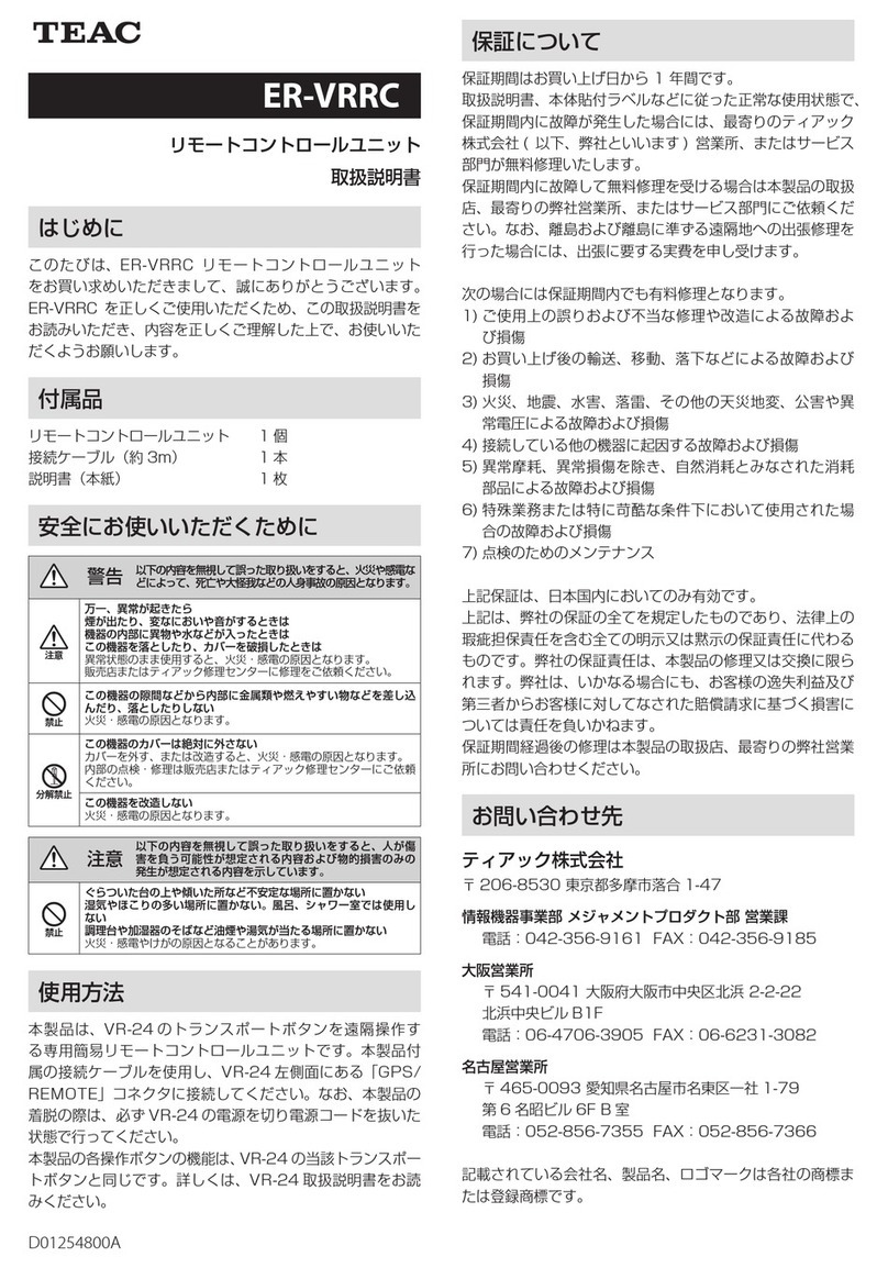
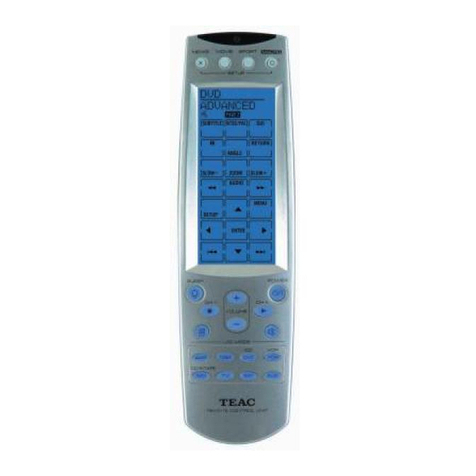
Teac ER-LXRC1000 User manual

Remote Control Unit
Instructions for Use
Z
ER-LXRC1000
D01349910F

2
1. IMPORTANT SAFETY INSTRUCTIONS ................3
2. Introduction. . . . . . . . . . . . . . . . . . . . . . . . . . . . . . . . . . . . . . . . 4
2-1.Disclaimers.....................................4
2-2.Included accessories ...........................4
3. Connections .......................................5
4. Names and functions of parts ......................6
4-1.Top.............................................6
4-2.Back............................................7
4-3.Turning the power on ..........................7
4-4.Putting the system into standby ................7
5. Basic operation.....................................8
5-1.Status changes .................................8
5-1-1. Explanation of status change diagram entry ..8
5-1-2.Status change diagram .....................8
5-2.Home Screen...................................9
5-3.Trigger settings display ........................10
5-4.Recording media information .................11
5-5.Panel locking ..................................11
5-6.Changing settings from the Home Screen .....11
5-7.Recording and playing data ...................12
5-8. Synchronization function ......................12
5-8-1.Synchronized recording settings...........12
5-8-2.Synchronized playback settings............13
5-8-3.VR-24 sync ................................13
6. Recording .........................................14
6-1.Order of procedures ...........................14
6-2.Setting recording conditions ..................14
6-3.Setting recording destination..................14
6-4.Calibration ....................................14
6-4-1.Equivalent input calibration ...............14
6-4-2.TEDS calibration ...........................14
6-4-3.Zero balancing ............................14
6-5.Setting triggers................................15
6-5-1.Trigger recording ..........................15
Recording starting conditions ..................15
Pre-trigger (PRE TRG) ...........................15
Recording stopping conditions.................15
Post-trigger (POST TRG) ........................15
Number of repetitions (REPETITIONS)...........15
6-5-2.Interval recording .........................16
6-6.Starting recording .............................16
6-6-1.Event mark ................................16
6-7.Stopping recording............................16
6-8.Recording format..............................17
6-8-1.Media folder structures ....................17
Folder structure example.......................17
7. Playback ..........................................18
7-1.Searching by ID ...............................18
7-2.Searching by COUNT ..........................19
7-3.Searching by event mark ......................19
7-4.Searching by time .............................19
8. Settings ...........................................20
8-1.Basic operation................................20
8-1-1.Selecting values from setting options......21
8-1-2.Inputting numbers as setting values .......21
8-1-3.Inputting characters as setting values......22
8-1-4.Opening submenu screens ................22
8-1-5.Opening higher-level Menu Screen pages .22
8-2.Menu structure................................23
8-2-1.SYSTEM menu structure ...................23
8-2-2.FILE menu structure .......................23
8-2-3.TRIGGER menu structure ..................24
8-2-4.MISC menu structure ......................24
8-3.SYSTEM .......................................25
8-3-1.TEDS ......................................25
8-3-2.MODULE SETTINGS........................26
8-3-3.PULSE SETTINGS...........................29
8-3-4.GPS SETTINGS .............................30
8-3-5.SYNC SETTINGS ...........................31
8-4.FILE ...........................................31
8-4-1.RECORDING FILE. . . . . . . . . . . . . . . . . . . . . . . . . . .31
8-4-2.OPEN FILE .................................32
8-4-3.DELETE FILE ...............................32
8-4-4.FORMAT...................................32
8-5.TRIGGER.......................................32
8-6.MISC ..........................................33
8-6-1.PARAMETER ...............................33
8-6-2.SET TIME ..................................34
8-6-3.LCD .......................................34
8-6-4.BEEP ......................................34
8-6-5.VERSION...................................34
8-6-6.BEEP ......................................35
8-6-7.VERSION...................................35
9. Specifications .....................................35
10. Warranty explanation..............................36
Contents
TEAC and TAFFmat are trademarks of TEAC CORPORATION,
registered in the U.S. and other countries.
Other company names, product names and logos are
the trademarks or registered trademarks of their respec-
tive owners.

3
1. IMPORTANT SAFETY INSTRUCTIONS
Model for USA
Supplier’s Declaration of Conformity
Model number: ER-LXRC1000
Trade name: TEAC
Responsible party: TEAC AMERICA,INC.
Address: 10410 Pioneer Blvd. Unit #1, Santa Fe Springs,
California90670, U.S.A.
Telephone number: 1-323-726-0303
This device complies with Part 15 of the FCC Rules.
Operation is subject to the following two conditions:
(1) this device may not cause harmful interference, and
(2) this device must accept any interference received,
including interference that may cause undesired
operation.
Information
This equipment has been tested and found to comply
with the limits for a Class A digital device, pursuant
to part 15 of the FCC Rules. These limits are designed
to provide reasonable protection against harmful
interference when the equipment is operated in a
commercial environment. This equipment generates,
uses, and can radiate radio frequency energy and, if
not installed and used in accordance with the instruc-
tion manual, may cause harmful interference to radio
communications. Operation of this equipment in a
residential area is likely to cause harmful interference
in which case the user will be required to correct the
interference at his own expense.
CAUTION
Changes or modifications not expressly approved by
the party responsible for compliance could void the
user’s authority to operate the equipment.
Model for Canada
Innovation, Science and Economic Development
Canada’s Compliance Statement:
This Class A digital apparatus complies with Canadian
ICES-003.
Cet appareil numérique de la classe A est conforme à
la norme NMB-003 du Canada.
Model for Europe
DECLARATION OF CONFORMITY
This product complies with the European
Directives request, and the other Commission
Regulations.
DECLARACIÓN DE CONFORMIDAD
Este producto cumple con las exigencias de las direc-
tivas europeas y con los reglamentos de la Comisión
Europea.
DÉCLARATION DE CONFORMITÉ
Ce produit est conforme aux directives européennes
et aux autres réglementations de la Commission
européenne.
KONFORMITÄTSERKLÄRUNG
Dieses Produkt entspricht den Anforderungen euro-
päischer Richtlinien sowie anderen Verordnungen
der Kommission.
Model for UK
This product complies with the applicable UK
regulations.
WARNING
This is a Class A product. In a domestic environment,
this product may cause radio interference in which
case the user may be required to take adequate
measures.
ATENCIÓN
Este es un producto de clase A. En un entorno no
profesional, este aparato puede producir interfe-
rencias de radio, en cuyo caso el usuario será el
responsable de tomar las medidas necesarias para
solucionarlo.
AVERTISSEMENT
Il s’agit d’un produit de Classe A. Dans un environne-
ment domestique, cet appareil peut provoquer des
interférences radio, dans ce cas l’utilisateur peut être
amené à prendre des mesures appropriées.
Warnung
Dies ist eine Einrichtung, welche die Funk-Entstörung
nach Klasse A besitzt. Diese Einrichtung kann im
Wohnbereich Funkstörungen versursachen; in
diesem Fall kann vom Betrieber verlang werden,
angemessene Maßnahmen durchzuführen und dafür
aufzukommen.

4
For European Customers
Disposal of electrical and electronic equipment
a)All electrical/electronic equipment should be disposed of separately from the municipal waste stream via collec-
tion facilities designated by the government or local authorities.
b) By disposing of electrical/electronic equipment correctly, you will help save valuable resources and prevent any
potential negative effects on human health and the environment.
c)Improper disposal of waste electrical/electronic equipment can have serious effects on the environment and
human health because of the presence of hazardous substances in the equipment.
d)The Waste Electrical and Electronic Equipment (WEEE) symbols, which show wheeled bins that have been
crossed out, indicate that electrical/electronic equipment must be collected and disposed of separately from
household waste.
e)Return and collection systems are available to end users. For more detailed information about the disposal of old
electrical/electronic equipment and waste batteries/accumulators, please contact your city office, waste disposal
service or the shop where you purchased the equipment.
Thank you for purchasing this remote control unit for
the LX-1000.
Please read the Instructions for Use for this product and
the main unit before using this product to maximize its
performance and ensure safe and proper operation.
2-1. Disclaimers
Information is given about products in this manual
only for the purpose of example and does not indicate
any guarantees against infringements of third-party
intellectual property rights and other rights related
to them. TEAC Corporation will bear no responsibility
for infringements on third-party intellectual property
rights or their occurrence because of the use of these
products.
2. Introduction
2-2. Included accessories
If anything is missing or damaged, contact us. (For con-
tact information, see the last page.)
For a list of included accessories, see “9. Specifications”
on page35.
1. IMPORTANT SAFETY INSTRUCTIONS

5
3. Connections
Mic
Use the included cable to connect the DIGITAL CONTROL
input/output connector on the back of the LX-1000 to
the TO LX-1000 control input/output connector on the
back of this unit.
To use a microphone, connect the microphone included
with the LX-1000 to the MEMO IN (mic input) jack.
ATTENTION
oWhen using the MEMO IN (mic input) jack on this unit,
the MEMO IN (mic input) jack on the LX-1000 cannot
be used.
oThis unit and LXK Navi cannot be used at the same
time.

6
4. Names and functions of parts
4-1. Top
A
B
C
D
E
F
H
G
A Display
This 3.5-inch TFT color display with 320×240 resolu-
tion shows various types of information.
NOTE
The display is produced with extremely high-precision
manufacturing technologies. At least 99.99% of the
pixels operate as specified. On rare occasions, a pixel
might misfire or appear as a red or black dot, but this
is not a malfunction.
B Function buttons (F1, F2, F3, F4)
C Transport buttons
8STOP button
Press to stop recording and playback.
0REC button
Press when the LX-1000 is stopped to make it record ready.
MARK
Press when recording to set an event mark.
oA maximum of 200 event marks can be added to
a single data file.
Play (7FWD) button
Press when the system is stopped or playback ready
to start playback.
Press when the unit is record ready to start recording.
9PAUSE button
Press when the system is stopped or playing back
to make it playback ready.
Press when recording to make it record ready.
Search (mREW/,F FWD) buttons
Use to search playback files.
ATTENTION
Press the transport buttons when the Home Screen
is open.
D VALUE dial
Turn when the selection position is shown to move
it. When inputting parameters, you can also use
these to increase or decrease values.
Turn clockwise while pressing the SHIFT button to
increase the speaker volume.
Turn counterclockwise while pressing the SHIFT
button to decrease the speaker volume.
E ENTER button
Press to select or confirm.
F MENU/HOME button
Press to open the Menu Screen or the Home Screen.
LOCK
Press for two seconds to lock the panel controls. Press
for two seconds again to unlock the panel controls.
G CANCEL button
H SHIFT button

7
4-2. Back
A B C
A TO LX-1000 external control input/output
connector
Use the included cable to connect this to the DIGITAL
CONTROL input/output connector on the back of
the LX-1000.
B MEMO IN (mic input) jack
Connect the included mic here to record voice
memos.
C STANDBY/ON switch
Press and hold this switch to turn the system on. Press
and hold it again to put the system into standby.
The light shows the status as follows.
Lit blue: Stopped
Blinking blue: Starting up
Unlit: In standby mode
4. Names and functions of parts
4-3. Turning the power on
Check the connections between the LX-1000 and
ER-LXRC1000 units, as well as their AC adapter connec-
tions. Then, press and hold the STANDBY/ON button on
either of them to turn them on.
The Home Screen will appear on the display.
4-4. Putting the system into standby
After confirming that the SD card is not being accessed,
press and hold the STANDBY/ON button on either the
LX-1000 or this unit to put them into standby.
ATTENTION
oIf the system is put into standby while data is being
written to the SD card, data recorded on it might
become unreadable.
oBefore moving this unit, stop power supply to the AC
adapter and the DC IN connector on the LX-1000.

8
5. Basic operation
5-1. Status changes
5-1-1. Explanation of status change diagram entry
Entries appear on the status change diagram in the following manner.
[0REC]
Stopped
Setting change
Status
Possible operations
Status change (by button or menu)
5-1-2. Status change diagram
The status of the LX-1000 will change in the following manner.
[0REC]
[7FWD]
[9PAUSE] [7FWD]
[8STOP]
[7FWD]
[9PAUSE]
[/F FWD]
[.REW]
[8STOP]
[8
STOP]
[9PAUSE]
[8STOP]
Stopped
[Select playback file]
[Stop playback]
[Turn power on]
Playback ready
Searching operation
PlayingRecording
Record ready
Playback and bar meter display
Recording and bar meter
display
Bar meter display
Setting change

9
5-2. Home Screen
a Status icon
Icon Status
8Stopped (ready for use)
p9 Record ready
pRecording
tPlaying back
t9 Playback ready
b ID
This shows the ID when playing back or recording.
When playback ready, select the ID and press the
ENTER button to conduct an ID search.
oIDs are consecutive file numbers inside playback
and recording folders. 999 is the highest number
that can be shown.
These do not always match the file name suffixes
(3digits).
oThe last recorded ID is shown when in a stopped
state.
c Recording/playback time (COUNT)
When recording, this shows the elapsed time since
recording started.
When playing back or playback ready, this shows
the elapsed time from the beginning of the file.
d Event mark (MARK)
When recording, this shows the total number of
event marks set in the data being recorded.
When playback ready, this shows the total number
of event marks set during recording.
NOTE
oPress the 0REC button when recording to set
an event mark.
oA maximum of 200 event marks can be added to
a single data file.
e Bar meters
Bar meters appear here during playback, recording
and when record ready.
The number of channels shown can be changed by
selecting a bar meter, pressing the ENTER button and
turning the VALUE dial. See “8-6. MISC” on page 33
to set the display unit and number of channels.
When all channels are not visible on a single screen,
the channels shown can be changed by pressing
the Disp.Module (F4) button
f File name
This shows the name of the file that will be recorded.
During playback and when playback ready, this
shows the name of the playback file.
g Date and time
This shows the current time of the LX-1000.
When playing back and when playback ready, this
shows when the recording was made.
See “8-6-2. SET TIME” on page34 to set the dis-
play format.
h Function buttons
This shows the current assignments of the Function
(F1, F2, F3, F4) buttons.
The functions shown change according to the open
screen.
i Folder name
This shows the name of the recording folder.
When playing back and when playback ready, this
shows the name of the playback folder.
j Information
Recording media information
This shows media capacity use and the playback
position (page11).
Status indicators
SHIFT button pressed
Buttons locked
LXK Navi connected
GPS satellite signal captured
Voice memo on
CAN recording available, CAN data not received
5. Basic operation

10
CAN recording available, CAN data received
Battery charge high*
Battery charge low*
Battery voltage low*
Using external power supply*
*These are shown when a BU-LX1000 battery unit is
connected.
NOTE
Battery charge indications are estimates.
Synchronization status indicators
These show the synchronization mode setting and
connection status.
Master mode, status OK
Master mode, status NG (not good)
Slave 1 mode, status OK
Slave 1 mode, status NG (not good)
Slave 2 mode, status OK
Slave 2 mode, status NG (not good)
Slave 3 mode, status OK
Slave 3 mode, status NG (not good)
k Settings
This shows setting values.
Item Explanation
SERIES Sampling series
SAMPLE Sampling frequency
AD Quantization bit depth
REC CH Number of recording channels
MONITOR Monitoring channel
TRIGGER Trigger setting
Select an item and press the ENTER button to enable
changing that setting value.
LXK Navi connection status
This is shown when LXK Navi is connected to an LX-1000.
This unit and LXK Navi cannot be used at the same time.
To use LXK Navi, turn the LX-1000 off once and disconnect
this device.
5. Basic operation
5-3. Trigger settings display
Stop trigger
Start trigger
The start and stop trigger settings are shown by icons.
No trigger
External trigger
Level trigger
Time
Timeout
If the mode is set to trigger and multiple triggers are set,
they are shown in the following order of priority.
Start triggers
Priority Trigger
1Level trigger
2External trigger
3Timeout
Stop triggers
Priority Trigger
1Level trigger
2External trigger
3Time

11
5-4. Recording media information
Media capacity use and
playback position display
Media and remaining space (hh:mm)
Media capacity use and playback position
display
The information shown changes according to the status
of this unit.
When playing back or playback ready
the elapsed time from the beginning of the file is
shown as a blue bar meter and as a %.
At all other times,
the amount of the current media space used is
shown as a green bar meter and as a %.
Media and remaining space
This shows the type of recording media and amount of
available recording time (hours: minutes).
5-5. Panel locking
Press at least
2seconds
Press the MENU/HOME button for two seconds to lock
the panel controls.
Press for two seconds again to unlock the panel controls.
NOTE
The icon appears on the Home Screen in the infor-
mation display area when the panel controls are locked.
5-6. Changing settings from the
Home Screen
Selection position
1 Turn the VALUE dial to change the selected
position.
The selected position is outlined in white.
2 Press the ENTER button.
When a Menu Screen item that can be set is selected,
a page for that item will open.
3 Turn the VALUE knob to select the setting value.
4 Press the ENTER button to conrm.
5. Basic operation

12
The settings of the following items can be changed
from the Home Screen.
Sampling series (SERIES) (page25)
Sampling frequency (SAMPLE) (page25)
Analog-digital conversion bit depth (AD) (page25)
Monitor channel (MONITOR) (page25)
5-7. Recording and playing data
Recording data can be saved on the LX-1000 SD card.
Install AR-LXAO1000 analog output amplifiers into the
LX-1000 as necessary.
ATTENTION
Data saved to an LX-1000 SD card can be played back.
Data saved to a computer cannot be played back.
1 Turn the LX-1000 on.
Wait until the Home Screen appears on the display.
2 Set the measurement conditions or load them.
Press the MENU/HOME button to open the Menu
Screen and make necessary settings (page20).
To load measurement conditions saved on the SD
card, select PARAMETER on the MISC screen. Then,
select LOAD. To save the current setting values,
select SAVE (page33).
ATTENTION
If an input/output amplifier module is changed, the
measurement conditions will be reset.
3 Record or play data.
Recording
Press the
0
REC button to make the system record
ready.
If a start trigger has been set, recording will start
when a trigger condition is met.
If no start trigger has been set, press the
7
FWD
button to start recording
(page16).
Playback
Press the 7FWD button to start playback. This will
start playback of the most recently recorded data.
To play another file, press the MENU/HOME button,
and select FILE. Then, select OPEN FILE to open the
playback folder selection window and select a file
for playback (page18).
5-8. Synchronization function
For details about master and slave unit connections,
refer to “Synchronization function” in the LX-1000
Instructions for Use.
See “8-3-5. SYNC SETTINGS” on page31 for informa-
tion about master and slave device settings.
5-8-1. Synchronized recording settings
If you set SAMPLING FREQ., AD BITS and DEVICE (record-
ing destination) for the master unit, they will also be set
for slave units automatically. These settings cannot be
changed on the slave units.
The number of recording channels can be set sepa-
rately for the master and slave units. An error will occur
if recording is conducted at a transmission rate higher
than the slave units can record.
Confirm that the numbers of recording channels on the
slave units are suitable before starting recording.
oSetting triggers on the slave units is not possible.
oThe following amount of time is necessary to start
synchronized recording from a stopped state.
Sampling frequency Starting delay
96kHz – 12kHz About 2 seconds
6kHz About 3 seconds
3kHz About 4 seconds
1.5kHz About 5 seconds
oLevel triggers and external triggers become effective
ten seconds after the unit becomes record ready.
oIf recording cannot be continued with the master
unit because, for example, it does not have enough
recording media capacity, recording will stop at that
moment.
If recording cannot be continued with a slave unit
because, for example, it does not have enough
recording media capacity, recording will stop only
for that unit. Other units will continue recording, but
pausing will stop recording.
5. Basic operation

13
5-8-2. Synchronized playback settings
After selecting files to play on the slave units, select the
file to play on the master unit.
If you select the file to play on the master unit first,
search by ID for the files to play on the slave units.
oIt is not possible to search the slave units using meth-
ods other than ID search. Use the master unit for
other search methods.
5. Basic operation
5-8-3. VR-24 sync
Preparation
1 Use a synchronization cable to connect the
SYNC OUT connector of the LX-1000 to the
VR-24/WX SYNC connector of the VR-24.
The VR-24 will operate as the slave unit.
2 Turn the VR-24 on.
3 Set the VR-24 Synchronization type to “WX
sync”.
4 Turn the LX-1000 on.
5 Use the LX-1000 Sync settings to set “MODE”
to “MASTER” and “SYNC NUMBER” to “2”. Then,
conduct“CHECK CONNECT.”
If there are no connection problems, the
“Syncronization status” will be “OK”.
6 Execute “ADJUST TIME” to set the time used by
the VR-24 to that used by the LX-1000.
The error is ±1 second.

14
6. Recording
6-1. Order of procedures
Set recording conditions
c
Set recording destination
c
Calibration
c
Set triggers
c
Make other settings
c
Start recording
c
Stop recording
6-2. Setting recording conditions
On the Menu Screen, make settings for the sampling
frequency, analog-digital conversion bit depth, voice
memos and modules (page25).
6-3. Setting recording destination
Set the file name for recording.
Set the recording destination on the FILE screen
(page31).
oSelect FORMAT on the FILE screen to format the SD
card loaded in the LX-1000.
oIf the ID number exceeds 999, recording will stop.
6-4. Calibration
Set the value used to convert sensor output to physical
quantities.
6-4-1. Equivalent input calibration
In the physical quantity conversion fields, set the rated
output and rated capacity indicated in the sensor test
report (page26).
6-4-2. TEDS calibration
TEDS data is not read automatically when the power is
turned on or when the TEDS sensor is changed.
TEDS data must be manually updated by pressing the
Update button (page25).
6-4-3. Zero balancing
Zero balance can be adjusted for channels with strain
amplifiers that have the amplifier mode set to ST.
1 Press the Zero Bal. (F3) button on the Home
Screen.
2 Turn the VALUE dial to change the selec-
tion position, and press the ENTER button to
change channel selection for zero balancing.
3 Press the Execute (F3) button to conduct zero
balancing.
oPress the Initialize (F2) button to cancel the zero
balancing adjustment results.
oPress the Check All (F4) button to select or deselect
all channels.

15
6. Recording
6-5. Setting triggers
In addition to manually starting and stopping recording,
you can also set the system to start and stop recording
using triggers and intervals. Make these settings on the
TRIGGER screen (page32).
The trigger recording operations are explained below.
ATTENTION
When using triggers and intervals to start recording
automatically, put the system into a record ready state.
The system will not detect triggers if just in a stopped
state.
6-5-1. Trigger recording
Example of one trigger recording repetition
Pre-trigger
Record ready
starts
Recording start
condition met
oLevel trigger
oExternal trigger
oTimeout
Recording
stops
Recording time Post-trigger
Recording stop
condition met
oLevel trigger
oExternal trigger
oRecording time
For trigger recording, you can set a combination of
recording starting conditions (level trigger, external
trigger or timeout) and recording stopping conditions
(level trigger, external trigger or recording time).
Recording starting conditions
Level trigger (LEVEL)
Use a level change for the set channel as a trigger.
External trigger (EXTERNAL)
Recording starts when the input through the external
trigger signal input (TRIG IN) connector becomes the L
level (0.4V or less).
Timeout (TIMEOUT)
If the conditions set to start recording are not met
within the set time, recording will be forced to start
automatically.
Pre-trigger (PRE TRG)
By default, the system saves data from the time between
when a recording starting condition occurs and when a
recording stopping condition occurs. When a pre-trigger
interval is set, data is recorded before a recording starting
condition occurs, but only after the system is made record
ready.
oDuring this interval, audio memos and CAN data will
not be recorded.
Recording stopping conditions
Level trigger (LEVEL)
Use a level change for the set channel as a trigger.
External trigger (EXTERNAL)
Recording stops when the input through the external
trigger signal input (TRIG IN) connector becomes the H
level (open or 2V or more).
Recording time (REC TIME)
Recording continues only for the set amount of time.
When set to 0, it will not stop at the recording time.
Post-trigger (POST TRG)
Even after recording stop conditions are met, recording
will continue for the set amount of time.
oWhen recording is stopped manually, however, post-
trigger recording will not occur.
Number of repetitions (REPETITIONS)
Set the number of repetitions.
If the number of repetitions is 2 or more, the system
will become record ready after recording stops the first
time. When the recording starting condition is realized,
recording will start again. This will repeat for the number
of repetitions. Then, recording will stop.
When set to 0, recording and pausing will repeat until
the recording media is full, the file name suffix would
exceed three digits or recording is stopped manually.
oWhen set to 0, if recording is repeated until the recording
media becomes full, the recorded data for the last record-
ing might not be as long as the recording time setting.
ATTENTION
Triggers cannot be monitored for two seconds after
becoming record ready, or after recording starting or
stopping conditions occur (10 seconds with synchro-
nized recording).
During this time, nothing will happen even if trigger
conditions occur.

16
6-5-2. Interval recording
Example of one interval recording repetition
Recording time
Start time
Recording starts
Recording
stops
With interval recording, when the Number of repetitions
is set to 1, recording will start at the Start time and stop
after the set Recording time has elapsed.
Example of three interval recording repetitions
Interval time
Recording
time
Recording
time
Recording
time
Interval time
Start time Recording
starts
Recording
starts
Record ready Record ready Recording
stops
Recording
starts
If the number of repetitions is set to 2 or more, record-
ing will start at the Start time and stop after the set
Recording time has elapsed. After the Interval time has
elapsed, recording will start again, repeating for the set
Number of repetitions. Then, recording will stop.
If the number of repetitions is set to 0, interval recording
will repeat until the recording media is full, or recording
is stopped manually.
Start time (START TIME)
Recording starts at the set time.
ATTENTION
If the set time has already passed when the system is
made record ready, recording will not start.
The system might take some time to become record
ready if, for example, there are already many recorded
files. Considering this, set the start time with sufficient
spare time.
Recording time (REC TIME)
Recording continues for the set amount of time.
Interval time (INTERVAL)
If the Number of repetitions is set to 2 or more record-
ings, this is the amount of time that the system stays in
a record ready state from the time one recording ends
until the next recording starts.
ATTENTION
oSet the Interval time to at least 6 seconds.
oEven if the system has manually been put in a record
ready state during the recording time, the next
recording will start after the originally set recording
time and interval time have elapsed.
Number of repetitions (REPETITIONS)
Set the number of repetitions. When set to 0, interval
recording will repeat until the recording media is full or
recording is stopped manually.
oWhen set to 0, if recording is repeated until the
recording media becomes full, the recorded data for
the last recording might not be as long as the record-
ing time setting.
6-6. Starting recording
Press the 0REC button to make the system record ready.
If a start trigger has been set, recording will start when a
trigger condition is met.
If no start trigger has been set, press the 7FWD button
to start recording.
6-6-1. Event mark
The 0REC button can be pressed when recording to set
an event mark.
oA maximum of 200 event marks can be added to a
single data file.
6-7. Stopping recording
If a stop trigger has been set, recording will stop when a
trigger condition is met.
If no stop trigger has been set, press the 8STOP button
to stop recording.
6. Recording

17
6-8. Recording format
The format used for recording data is TAFFmat.
See the LX-1000 Instructions for Use for details about the TAFFmat format.
6-8-1. Media folder structures
Folder type Name Details
Master folder LXDAT
This is created in the root folder.
Data is managed inside it.
The name is fixed.
Project folders Characters as set
(Example: LX1000-DIR1)
These are created in the master folder.
Their names can be set as desired.
Recording folders Characters as set
(Example: LX1000_)
These are created in project folders.
Their names can be set as desired.
Each time recording starts, a recording folder is created with a
3-digit suffix added automatically.
Recording data Same as recording folder When a recording is divided at 4GB, a - (hyphen) followed by a
three-digit suffix will be added to the name.
Folder structure example
root sRoot folder
LXDAT sMaster folder
LX1000-DIR1 sProject folder
LX1000_001 sRecording folder
LX1000_001.HDX sIndex file
LX1000_001.DAT
LX1000_001.HDR
LX1000_001.GPS
LX1000_001.WAV Recording data
LX1000_001.CAN
LX1000_001.CNX
LX1000_001-002.DAT
LX1000_001-002.HDR
LX1000_001-002.WAV Divided data
LX1000_001-003.DAT
LX1000_001-003.HDR
LX1000_001-003.WAV
LX1000_002 sRecording folder
LX1000_002.HDX sIndex file
LX1000_002.DAT
LX1000_002.HDR
LX1000_002.GPS Recording data
LX1000_002.WAV
LX1000_002.CAN
LX1000_002.CNX
...
LX1000-DIR2 sProject folder
...
6. Recording

18
7. Playback
Install AR-LXAO1000 analog output amplifiers into the
LX-1000 as necessary.
ATTENTION
Data saved to an LX-1000 SD card can be played back.
Data saved to a computer cannot be played back.
1 Press the MENU/HOME button, and select FILE,
then OPEN FILE to open the playback folder
selection window.
2 Select a folder, select the playback file, and
press the ENTER button to start playback.
Playback will start and playback data will be shown
on the Home Screen.
During playback, the following buttons are enabled.
.: Skip to previous recorded data
/: Skip to next recorded data
NOTE
To play the most recently recorded data, press the
7FWD button when the Home Screen is open
without selecting a file.
3 Press the 8STOP button to stop playback.
7-1. Searching by ID
When the unit is playback ready, select ID on the Home
Screen and set the ID to search for. Then, press the
ENTER button to search for the set ID position and start
playback.

19
7. Playback
7-2. Searching by COUNT
When the unit is playback ready, select the playback
time (COUNT) on the Home Screen and set the play-
back time to search for. Then, press the ENTER button to
start playback from the specified playback time position.
oUse the F3 and F4 buttons to switch between the
hours, minutes and seconds.
7-3. Searching by event mark
When the unit is playback ready, select the event mark
(MARK) on the Home Screen and set the mark to search
for. Then, press the ENTER button to start playback from
the specified mark position.
7-4. Searching by time
When the unit is playback ready, select the time display
on the Home Screen and set the time to search for.
Then, press the ENTER button to start playback from the
specified time.
oUse the F3 and F4 buttons to switch between the
year, month, day, hour, minute and second.

20
Settings can be changed on the Menu Screen. Settings
that are used frequently can also be changed on the
Home Screen.
8-1. Basic operation
Follow these procedures to change settings using the
Menu Screen.
1 Press the MENU/HOME button to open the
Menu Screen.
The title of the open menu page is underlined.
Menu page title
Selection position
Press the MENU/HOME button to cycle through the
Menu Screen pages in the following order.
SYSTEM FILE TRIGGER MISC
2 Turn the VALUE dial to change the selected
position.
3 Press the ENTER button.
If you select an item that has its current value
shown to its right, a list of values opens and you
can change the selected item’s setting.
The following screen shows an example of a selec-
tion from the setting value options. See “8-2-1.
SYSTEM menu structure” on page 23 for opera-
tion procedures.
oSee “8-2-1. SYSTEM menu structure” on page23
for how to input characters for setting values.
oWhen special operations are required for a setting,
they are explained together with its setting values.
When a setting item with a tto its right is selected,
a submenu will open. See “8-2-1. SYSTEM menu
structure”on page23.
4 When you are done changing settings, press
the MENU/HOME button to return to the Home
Screen.
oWhen a submenu screen is open, press the MENU/
HOME button to return to the Menu Screen page
above it.
You can also press the CANCEL button to return
to the Menu Screen page above it.
8. Settings
Table of contents
Other Teac Control Unit manuals
Popular Control Unit manuals by other brands

Weir
Weir SPM EXL Operation Instruction and Service Manual

Pepperl+Fuchs
Pepperl+Fuchs PXV Series quick start guide

Maxon
Maxon ESCON 50/5 Hardware reference

Texas Instruments
Texas Instruments HSS-MOTHERBOARDEVM user guide

Kilowatt Labs
Kilowatt Labs SIRIUS 5000-384-A-1C-TM-SD-A-X-X-G user manual

Buderus
Buderus Logamatic 4323 operating instructions

Cisco
Cisco CSS 11500 Reference

National Instruments
National Instruments SCXI-1160 user manual

Acromag
Acromag PMC341 Series user manual

Potter
Potter PAD100-SM installation manual

Emerson
Emerson Kunkle Valve Series Installation and operating instructions

Dynamite
Dynamite DYN4073 Installation and operation guide