manuals.online logo
Brands
  1. Home
  2. •
  3. Brands
  4. •
  5. Cisco
  6. •
  7. Control Unit
  8. •
  9. Cisco CSS 11500 Service manual

Cisco CSS 11500 Service manual

Corporate Headquarters:
Copyright © 2003. Cisco Systems, Inc. All rightsreserved.
Cisco Systems,Inc., 170 West Tasman Drive, San Jose, CA 95134-1706USA
Cisco 11500 Series Content Services Switch
Switch Control Module Reference
The CSS 11500 series Switch Control Module (SCM) provides master control and is responsible for the
following functions: system powerup and boot control, centralized routing table management,
system-wideconnection management,and interface toanexternal NetworkManagementStation.
Figure1shows an SCM (CSS5-SCM-2GE=).
Figure1SCMLEDs and Connectors
Only one SCM is required in a configuration, however you can install and configure a second SCM for
redundancy in a CSS 11506. A secondary SCM is passive, and does not load share processing functions
with the primary module. If the primary SCM fails, theCSS reboots and connections are terminated.
Thenthe secondary SCMbecomes primary automatically.
110-Mbps half-duplexEthernet
management connector 7Link and activity LEDfor the associated GBIC
connectorontheleft
2Bicolorstatus LED (green and red) 8RJ-45RS-232Console connector
3Amber status LED 9RJ-45 RS-232 Diag connector forfield service
diagnostic use only (A connectorcover is
provided. Removing the cover voidsthewarranty.)
4Link/Act LED
5Duplex LED 10 PCMCIA slotcover
6LC-type SFP GBICs (one of two) 11 PCMCIA slot 0 on the bottomcontaining a flash or
hard disk and slot 1 on top (shown empty)
59531
CSS5-SCM-2GE
SystemControl
DUPLEX
LINK/ACT
MANAGEMENT
10BASE-T
SLOT0
SLOT1
GE1 GE2 LINK
LINK
STATUS
PCMCIA
CONSOLE
2
19
8
3
4
5
6
7
10 11
2
Cisco11500 Series Content Services SwitchSwitch Control Module Reference78-13711-03
Note Beforeyou remove or install a module, make sure you properly ground yourself prior to handling the
module. For example,wearan antistaticwriststrap (included in the kit withthe module)and stick
the copper-tape end of the strap to an unpainted metal surface on the chassis. Make sure that the wrist
strap makes good contact with your skin.
Removing theSCM
Caution You must power down the CSS to removean SCM. If you remove a powered-on SCM from an
operational CSS, the CSS terminates all communications and reboots.
To remove anSCM:
1.Locatethe failed SCM (its Status LEDs willbe off). See Figure1.
2.If necessary, power down theCSS.
3.Remove all cablesfrom the module.
4.With a Phillips screwdriver, remove the PCMCIA cover and thenloosen the spring-loaded screws
on the frontof the modulefaceplate. See Figure2.
Figure2Removingthe PCMCIA Cover fromthe SCM
5.Extend both ejectors simultaneously to unseat themodule connector from the backplane and slide
the module out ofthe slot.
59602
CSS5-SCM-2GE
SystemControl
DUPLEX
LINK/ACT
MANAGEMENT
10BASE-T
SLOT0
SLOT1
GE1 GE2 LINK
LINK
STATUS
PCMCIA
CONSOLE
3
Cisco 11500 Series Content Services Switch Switch ControlModule Reference
78-13711-03
6.Remove the SFP GBICs from the SCM. Press the ejectors on the SFP GBICs. Slide them out of the
module and set them aside. See Figure3.
Figure3Ejecting theSFP GBIC from theSCM
7.Remove the flash or hard disks from the SCM. Press the ejectors to the rightof the disks. Slide them
out of the module and set them aside. See Figure4.
Figure4Ejecting theDiskfrom the SCM
Note Thereplacement SCM contains a 144 MB Small OutlineRamBus InlineMemory Module
(SO-RIMM). If your failed module has a288 MB SO-RIMM, you must remove its SO-RIMM, and
place it in the replacement SCM. See“Removing and Replacing the Memory Module” later in this
document.
Installingthe SCM
To install an SCM (refer to the previous illustrations):
1.Properly ground yourself prior to handlingthe module, as noted on the previous page.
2.If applicable, reinstallthe memory module, SFP GBICs, and flash or hard disks in the SCM.
3.Locate the slot in the chassis for the SCM. SCMs are restricted to slots 1 and 2.
1SFP GBIC ejector
123
CSS5-SCM-2GE
SystemControl
DUPLEX
LINK/ACT
MANAGEMENT
10BASE-T
SLOT0
SLOT1
GE1GE2 LINK
LINK
STATUS
PCMCIA
CONSOLE
67902
GE2
1
1Disk ejector
123
CSS5-SCM-2GE
SystemContl
DUPLEX
LINK/ACT
MANAGEMENT
10BASE-T
SLOT0
SLOT1
GE1GE2 LINK
LINK
STATUS
PCMCIA
CONSOLE
59532
1
4
Cisco11500 Series Content Services SwitchSwitch Control Module Reference78-13711-03
4.Insertthe moduleinto the board guides atthe left and right sides of the slot, and then slidethe
module into the chassis bypressing firmly at the leftand right of the faceplate.
5.Close both ejectors simultaneously to seatthe moduleconnector into the backplane.
6.Using aPhillips screwdriver,tighten the spring-loaded screws on the front ofthe module faceplate.
7.With a Phillips screwdriver, replace the PCMCIA cover (see Figure2) and then tighten the
spring-loadedscrews on the front of the modulefaceplate.
8.Replace the cables. Note that the SFP GBICs haveLC-type connectors and require LC-type fiber
cables.
9.Reboot the CSS.
10.If you installed a secondary SCM, use the passive sync command to copy the boot config from the
primary SCM to the secondary SCM.
If you installed a replacement for a primary SCM,the replacementhas defaultsettings for the
administrative username and password, IP address, subnet mask, and primary boot record. To
reconfigure these parameters, access the Offline Diagnostic Monitor menu at the boot prompt. For
information on using the Offline Diagnostic Monitor menu, refer to the Content Services Switch
Administration Guide.
Table 1 describes the SCM LEDs and their indications.
Related CLI Commands
To view the current state of the SCM and verify it is powered on as indicated by the primary or secondary
state,use the show chassis command.
Table1SwitchControl Module LED Descriptions
LED Name Color State Indicates
Status (left) Green Solid The moduleis ready.
Variable blink Disk activity isoccurring.
Slow blink Another CSS module has failed.
Red Solid The module failed the power-up self test during the boot
process.
Slowblink The modulefailed.
No colorOffThe modulefailedand has no power.
Status (right) Amber Slow blink The moduleis offline and active.
Solid The moduleis onlineand not active(secondary).
Link/Act
for the Ethernet
Management Port
Green OffThere is no link.
On The link is established butthere is no activity.
Blinking The link is established with transmit or receive activity.
Link
for each Gigabit
Ethernet Port
Green OffThere is no link.
On The link exists and synchronization isachieved.
Blinking The link is established with transmit and receive activity.
5
Cisco 11500 Series Content Services Switch Switch ControlModule Reference
78-13711-03
Removing and Replacingthe Memory Module
To remove and replace amemorymodule:
1.Place the modulefaceup on a flat antistatic surface.
2.Locate the SO-RIMM connector on the rear of the module. See Figure 5.
Figure5MemoryModule Location
3.Slightly extend the locking tabs on both sides of the memory module to release it. Gently pull the
module out of the connector. See Figure 6.
Figure6MemoryReplacement
4.Align the replacement memory module so that the rowof gold contacts on thememory module are
facingtherow ofgoldpins insidetheconnector.
5.Insertthe memory module into the connector at approximately a 30 degree angle (see Figure 6) and,
with gentle pressure, push the module into the connector until the module fits snugly against the
back of theconnector. At this point, themodule is still at an angle above the locking tabs.
6.Gently push straight down on the edges of the module until the tabs lock itinto place.
1Memory module
SystemControl
1
59620
1SO-RIMM connector tab
59547
1
6
Cisco11500 Series Content Services SwitchSwitch Control Module Reference78-13711-03

Other Cisco Control Unit manuals

Cisco LightStream 1010 Quick start guide

Cisco

Cisco LightStream 1010 Quick start guide

Cisco FlexWAN User manual

Cisco

Cisco FlexWAN User manual

Cisco MEM-NP8F Series Quick start guide

Cisco

Cisco MEM-NP8F Series Quick start guide

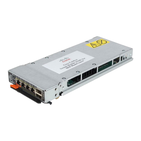
Cisco Catalyst 3110G Manual

Cisco

Cisco Catalyst 3110G Manual

Cisco GS7000 Operator's manual

Cisco

Cisco GS7000 Operator's manual

Cisco WS-SVC-WISM2-1-K9 Quick start guide
Cisco

Cisco WS-SVC-WISM2-1-K9 Quick start guide

Cisco T1 User manual

Cisco

Cisco T1 User manual

Cisco WS-G5484 User manual

Cisco

Cisco WS-G5484 User manual

Cisco HPNA User manual

Cisco

Cisco HPNA User manual

Cisco EHWIC-3G-EVDO User manual

Cisco

Cisco EHWIC-3G-EVDO User manual

Cisco T3 Quick start guide

Cisco

Cisco T3 Quick start guide

Cisco MEM-CIP-64M User manual

Cisco

Cisco MEM-CIP-64M User manual

Cisco ONS 15200 User manual

Cisco

Cisco ONS 15200 User manual

Cisco Beacon Point Module Manual

Cisco

Cisco Beacon Point Module Manual

Cisco NCS 1004 User manual

Cisco

Cisco NCS 1004 User manual

Cisco TelePresence MCU 4200 Series User manual
Cisco

Cisco TelePresence MCU 4200 Series User manual

Cisco GS7000 Operating instructions

Cisco

Cisco GS7000 Operating instructions

Cisco 3600 Series Quick start guide

Cisco

Cisco 3600 Series Quick start guide

Cisco NM-1E2W Quick start guide

Cisco

Cisco NM-1E2W Quick start guide

Cisco SCE8000 GBE User manual

Cisco

Cisco SCE8000 GBE User manual

Cisco Catalyst WS-X3001 Operator's manual

Cisco

Cisco Catalyst WS-X3001 Operator's manual

Cisco MGX RPM-XF User manual

Cisco

Cisco MGX RPM-XF User manual

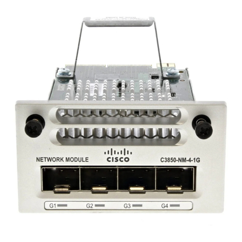
Cisco C3850-NM-4-1G Instruction Manual
Cisco

Cisco C3850-NM-4-1G Instruction Manual

Cisco NM-1CT1 Quick start guide

Cisco

Cisco NM-1CT1 Quick start guide

Popular Control Unit manuals by other brands

Estyma VIDENET user manual

Estyma

Estyma VIDENET user manual

Beninca KT3 operating instructions

Beninca

Beninca KT3 operating instructions

Lenze EMF2133IB Communications manual

Lenze

Lenze EMF2133IB Communications manual

PRASTEL M1000 quick start guide

PRASTEL

PRASTEL M1000 quick start guide

MICRO-EPSILON IF1032/ETH instruction manual

MICRO-EPSILON

MICRO-EPSILON IF1032/ETH instruction manual

SIIG 1 FireWire 800 CardBus DV-Ki Quick installation guide

SIIG

SIIG 1 FireWire 800 CardBus DV-Ki Quick installation guide

AMOT G Series Installation, operation and maintenance manual

AMOT

AMOT G Series Installation, operation and maintenance manual

Sony HSCU300RF Operation guide

Sony

Sony HSCU300RF Operation guide

CLIVET HWM-2-XMi 140 manual

CLIVET

CLIVET HWM-2-XMi 140 manual

Parrot FC6100 ASPEN Use manual

Parrot

Parrot FC6100 ASPEN Use manual

Z-Wave PAN05-1B quick start guide

Z-Wave

Z-Wave PAN05-1B quick start guide

Runxin F104 A user manual

Runxin

Runxin F104 A user manual

Mitsubishi Electric MELSEC iQ-R Series user manual

Mitsubishi Electric

Mitsubishi Electric MELSEC iQ-R Series user manual

Wayne and Layne Tactile Metronome Build instructions

Wayne and Layne

Wayne and Layne Tactile Metronome Build instructions

Boge FOCUS operating instructions

Boge

Boge FOCUS operating instructions

Copley Controls Corp. Accelnet Micro Module manual

Copley Controls Corp.

Copley Controls Corp. Accelnet Micro Module manual

Franke ZAQUA030 Installation and operating instructions

Franke

Franke ZAQUA030 Installation and operating instructions

Audiovox CS owner's manual

Audiovox

Audiovox CS owner's manual

manuals.online logo
manuals.online logoBrands
  • About & Mission
  • Contact us
  • Privacy Policy
  • Terms and Conditions

Copyright 2025 Manuals.Online. All Rights Reserved.