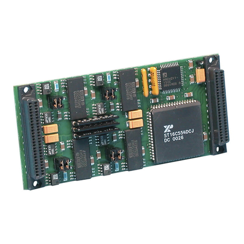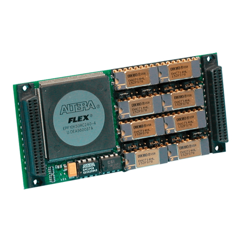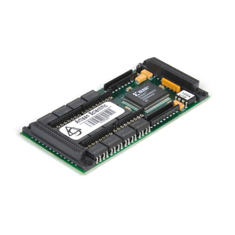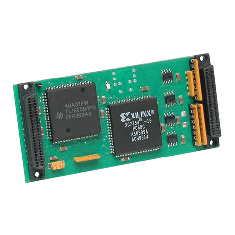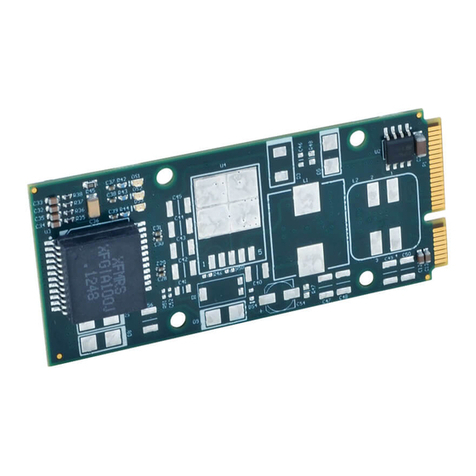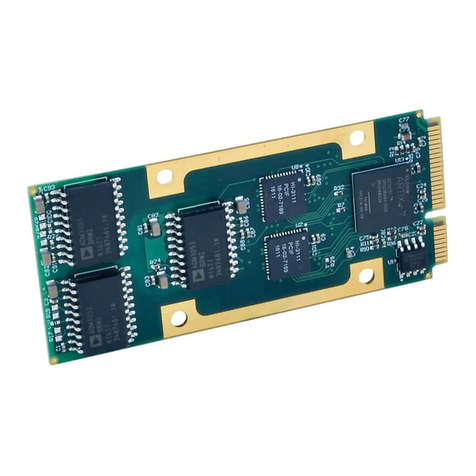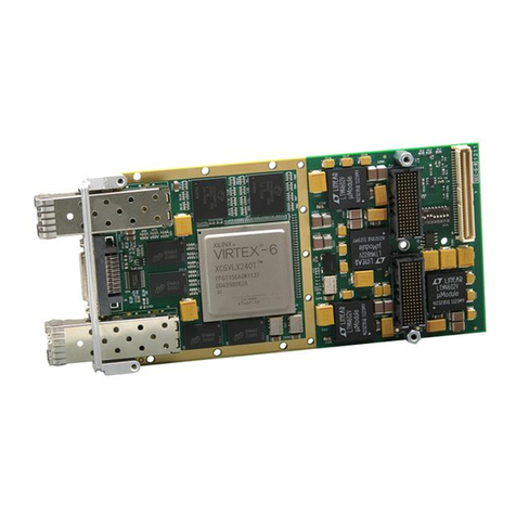
SERIES PMC341 PCI MEZZANINE CARD SIMULTANEOUS ANALOG INPUT MODULE
___________________________________________________________________________________________
-
-
The PMC341 modules are available in standard or extended
temperature range as follows:
Note: PMC341R and PMC341RE are rear field I/O models, only.
All other models have front I/O.
KEY PMC341 FEATURES
14-Bit ADC Resolution - Eight individual 14-bit successive
approximation Analog to Digital Converters (ADC) with
integral sample and hold are utilized.
8sec Conversion Time - A maximum conversion rate of
125KHz is supported.
Two 512 Sample Memory Buffers –Two 512 sample deep
memory buffers are available to reduce CPU interactions.
While new digitized data is written to one memory buffer,
data can be read from the other at burst data rates. This
allows the external processor to service more tasks within a
given time. Data tagging is also implemented for easy
channel data identification.
Memory Buffers Switch Condition –When the number of
new data samples exceed a programmable threshold value
the input buffer switches to the data read buffer which allows
reading of the new data. The old read buffer will
simultaneously switch from the data read to the data input
buffer.
Interrupt Upon Reaching a Memory Threshold Condition
–An interrupt can be generated when the number of new
data samples reaches a programmable threshold condition.
This feature can be used to minimize CPU interaction.
Programmable Control of Channels Converted - Up to 16
differential analog inputs are monitored. Channels 0 to 7 are
simultaneously converted followed by the simultaneous
conversion of channels 8 to 15. Channels may be
individually enabled/disabled for simultaneous conversion.
User Programmable Conversion Timer - A programmable
conversion timer is available to control the time between
simultaneous conversion of new banks of channel data. For
example, channels 0-7 are converted immediately upon
trigger and then channels 8-15 are converted after a user
programmable delay from the start of the first eight
channels. An overall count value is also used to control
when conversions will start again for the first eight channels.
Supports a maximum interval of 2.09 seconds.
Continuous Conversion Mode - All channels selected for
conversion are continually digitized with the interval between
conversions controlled by the user programmed conversion
timer registers. Scanning is initiated by a software or
external trigger. Scanning is stopped by software control.
Single Cycle Conversion Mode - All channels selected for
conversion are digitized once with the time between
channels 0 to 7 and 8 to 15 controlled by a programmable
timer. Single cycle conversion mode is initiated by a
software or external trigger.
External Trigger Input or Output - The external trigger is
assigned to a field I/O line. This external trigger may be
configured as an input, output, or disabled. As an output
this signal provides a means to synchronize other modules
to a single PMC341 timer reference. As an input the signal
will trigger the PMC341 hardware to initiate data
conversions.
Precision On Board Calibration Voltages - Calibration
autozero and autospan precision voltages are available to
permit host computer correction of conversion errors. The
calibration voltages can be converted and then compared to
the expected value stored in on board memory. Calibration
voltages include: 0V (local analog ground), and a precision 5
volt reference.
Fault Protected Input Channels - Analog input overvoltage
protection to +/-25V with power on and +/-40V with power
off.
PCI MEZZANINE CARD INTERFACE FEATURES
High density - Single-width PMC Target module.
Field Connections –All analog input, trigger, and power
connections are made through a single 50-pin SCSI-2 front
panel I/O connector. Models PMC341R and PMC341RE,
only use a 64 pin rear I/O connector.
32, 16, 8-bit I/O - Register Read/Write is performed through
data transfer cycles in the PCI memory space. All registers
can be assessed via 32, 16, or 8-bit data transfers.
Compatibility –IEEE P1386.1 compliant PMC module
which complies to PCI Local Bus Specification Revision 2.2.
Provides one multifunction interrupt. 5V signaling compliant
and 3.3V signaling tolerant.
SIGNAL INTERFACE PRODUCTS
(See Appendix for more information on compatible products)
This PMC Module will mate directly to any standard PMC
carrier board that supports one single width PMC mezzanine
module. Once connected, the module is accessed via a 50 pin
front panel connector.
The cables and termination panels, described in the following
paragraphs, are also available. For optimum performance with
the PMC341 analog input module, use of the shortest possible
length of shielded input cable is recommended.
Cables:
Model 5025-187 (SCSI-2 to Flat Ribbon Cable, Shielded): A
round 50 conductor shielded cable with a male SCSI-2
connector at one end and a flat female ribbon connector at
the other end. The cable is used for connecting the PMC341
module to Model 5025-552 termination panels.
Termination Panel:
Model 5025-552: DIN-rail mountable panel provides 50 screw
terminals for universal field I/O termination. Connects to
Acromag PMC341, via SCSI-2 to Flat Ribbon Cable,
Shielded (Model 5028-187).
PMC MODULE ActiveX CONTROL SOFTWARE
Acromag provides a software product (sold separately)
consisting of PMC module ActiveX (Object Linking and
Embedding) drivers for Windows 98, 95, ME, 2000 and
Windows NTcompatible application programs (Model PMCSW-
ATX, MSDOS format). This software provides individual drivers
that allow Acromag PMC modules to be easily integrated into
Windowsapplication programs, such as Visual C++, Visual
Basic, MicrosoftOffice97 applications and others. The
ActiveX controls provide a high-level interface to PMC modules,


