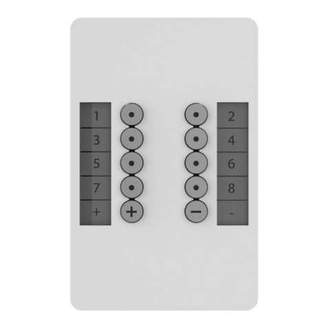
Team Digital SRC16 User manual

Cont. Summary of Configuration Variables
>DCC compatible accessory decoder
> Control switches (turnouts)
> Drive switch status LEDs
> Drive low current switch machines
> Eight configurable routes
> 16 Individually configurable inputs & outputs
> Featuring “Smart” Programming
>DCC gateway to serial bus
> LocoNet® compatible
TEAM DIGITAL
WARNING: This product contains a chemical known to thestate of
California to cause cancer, birth defects or other reproductive harm.
16
03.28.11 V16
LocoNet is a registered
trademark of Digitrax Inc
TEAM DIGITAL, LLC
3111 Timber Valley Dr
Kokomo IN 46902
www.teamdigital1.com
CV#
Function/Default Value
CV#
Function/Default Value
173
Route 3 Cell 7 Address Adder
0
215
Route 6 Cell 4 Address Adder
0
174
Route 3 Cell 8 Address
0
216
Route 6 Cell 5 Address
0
175
Route 3 Cell 8 Address Adder
0
217
Route 6 Cell 5 Address Adder
0
176
Route 4 Cell 1 Address
0
218
Route 6 Cell 6 Address
0
177
Route 4 Cell 1 Address Adder
0
219
Route 6 Cell 6 Address Adder
0
178
Route 4 Cell 2 Address
0
220
Route 6 Cell 7 Address
0
179
Route 4 Cell 2 Address Adder
0
221
Route 6 Cell 7 Address Adder
0
180
Route 4 Cell 3 Address
0
222
Route 6 Cell 8 Address
0
181
Route 4 Cell 3 Address Adder
0
223
Route 6 Cell 8 Address Adder
0
182
Route 4 Cell 4 Address
0
224
Route 7 Cell 1 Address
0
183
Route 4 Cell 4 Address Adder
0
225
Route 7 Cell 1 Address Adder
0
184
Route 4 Cell 5 Address
0
226
Route 7 Cell 2 Address
0
185
Route 4 Cell 5 Address Adder
0
227
Route 7 Cell 2 Address Adder
0
186
Route 4 Cell 6 Address
0
228
Route 7 Cell 3 Address
0
187
Route 4 Cell 6 Address Adder
0
229
Route 7 Cell 3 Address Adder
0
188
Route 4 Cell 7 Address
0
230
Route 7 Cell 4 Address
0
189
Route 4 Cell 7 Address Adder
0
231
Route 7 Cell 4 Address Adder
0
190
Route 4 Cell 8 Address
0
232
Route 7 Cell 5 Address
0
191
Route 4 Cell 8 Address Adder
0
233
Route 7 Cell 5 Address Adder
0
192
Route 5 Cell 1 Address
0
234
Route 7 Cell 6 Address
0
193
Route 5 Cell 1 Address Adder
0
235
Route 7 Cell 6 Address Adder
0
194
Route 5 Cell 2 Address
0
236
Route 7 Cell 7 Address
0
195
Route 5 Cell 2 Address Adder
0
237
Route 7 Cell 7 Address Adder
0
196
Route 5 Cell 3 Address
0
238
Route 7 Cell 8 Address
0
197
Route 5 Cell 3 Address Adder
0
239
Route 7 Cell 8 Address Adder
0
198
Route 5 Cell 4 Address
0
240
Route 8 Cell 1 Address
0
199
Route 5 Cell 4 Address Adder
0
241
Route 8 Cell 1 Address Adder
0
200
Route 5 Cell 5 Address
0
242
Route 8 Cell 2 Address
0
201
Route 5 Cell 5 Address Adder
0
243
Route 8 Cell 2 Address Adder
0
202
Route 5 Cell 6 Address
0
244
Route 8 Cell 3 Address
0
203
Route 5 Cell 6 Address Adder
0
245
Route 8 Cell 3 Address Adder
0
204
Route 5 Cell 7 Address
0
246
Route 8 Cell 4 Address
0
205
Route 5 Cell 7 Address Adder
0
247
Route 8 Cell 4 Address Adder
0
206
Route 5 Cell 8 Address
0
248
Route 8 Cell 5 Address
0
207
Route 5 Cell 8 Address Adder
0
249
Route 8 Cell 5 Address Adder
0
208
Route 6 Cell 1 Address
0
250
Route 8 Cell 6 Address
0
209
Route 6 Cell 1 Address Adder
0
251
Route 8 Cell 6 Address Adder
0
210
Route 6 Cell 2 Address
0
252
Route 8 Cell 7 Address
0
211
Route 6 Cell 2 Address Adder
0
253
Route 8 Cell 7 Address Adder
0
212
Route 6 Cell 3 Address
0
254
Route 8 Cell 8 Address
0
213
Route 6 Cell 3 Address Adder
0
255
Route 8 Cell 8 Address Adder
0
214
Route 6 Cell 4 Address
0
SRC16
Switch & Route Controller
Improving the
world of DCC
or 9 -12 V DC
use only with an
accessory bus

1 Operation
The SRC16 has 16 inputs and outputs which can each have a unique address. By assigning
the same address to a pair of inputs and outputs, called a group, the SRC16 can control eight
turnouts (switches) or display the state (closed or thrown) of eight turnouts. If the serial bus
(LocoNet® compatible) is enabled, activating an input (close or throw) sends a turnout
command (message) that correspond to it’s address over the serial bus. Any device con-
nected to the bus can receive the command. The SRC16 monitors the bus for commands
from other sources. When a turnout command is received with an address that matches a
group’s address, that output (closed or thrown) is activated. LEDs or stall motors can be
connected to the outputs. The SRC16 does not require a serial bus connection to operate. It
receives it’s own messages.
The SRC16 supports eight routes. Each route has eight cells. There is one top or route exe-
cution address for each route. Each top address is completely independent of an input or
output address.
Any input can be used for turnout position reporting which tells the system the actual state
(closed or thrown) of the turnout. Any input can be used for sensor state reporting such as
track block occupancy.
Since the SRC16 is a accessory decoder, it can be controlled via DCC commands. It can
also be controlled via the serial bus (LocoNet® compatible). For non-Digitrax systems a
DCC gateway feature allows DCC switch commands to be passed directly to the serial bus.
This allows DCC switch commands to control devices connected to this serial bus.
LED 1 flashes indicates “Smart” programming steps. LED 2 flash indicates accepted pro-
gram value. LED 3 slow flash indicates heartbeat (fast flash indicates serial bus short).
2 Getting Started
The SRC16 comes from the factory ready to use with inputs and outputs configured in
groups of two with group addresses of 1 to 8. Once you connect LEDs and/or stall motors to
the outputs and perhaps a push button or other device to the inputs, you are ready to connect
to track power and use the SRC16. If you want to change some of the output or input ad-
dresses or configuration values see the “Smart” Programming section. For very custom
programming see section 4, Configuration Variables for various options. If you will be us-
ing Team Digital MotoDs with the SRC16 see section 5.4.
2.1 Control via LocoNet®- Digitrax Users
The SRC16 comes from the factory ready to use by control from DCC commands when the
SRC16 is connected to track power. To control the SRC16 via LocoNet®, it must be en-
abled. Connect the SRC16 track power terminals to the programming track and program
CV9 with a value of 48. The SRC16 can now be powered from a 12 volt supply and con-
trolled via LocoNet®.
3 “Smart” Programming
“Smart” programming is a term used to describe an easy way to program Configuration
Variables (CVs). The throttle is used to issue switch or accessory commands just like con-
trolling switches (turnouts). “Smart” programming only works when connected to track
power.
To program in “Smart” mode, connect the SRC16 power terminals to track power. Connec-
tion to the serial bus (LocoNet® in Digitrax system) is not used. Turn on power.
2 15
CV#
Function/Default Value
CV#
Function/Default Value
87
Output 8 Control
0
130
Route 1 Cell 2 Address
0
88
Output 9 Address
5
131
Route 1 Cell 2 Address Adder
0
89
Output 9 Type & Address Adder
0
132
Route 1 Cell 3 Address
0
90
Output 9 Control
0
133
Route 1 Cell 3 Address Adder
0
91
Output 10 Address
5
134
Route 1 Cell 4 Address
0
92
Output 10 Type & Address Adder
64
135
Route 1 Cell 4 Address Adder
0
93
Output 10 Control
0
136
Route 1 Cell 5 Address
0
94
Output 11 Address
6
137
Route 1 Cell 5 Address Adder
0
95
Output 11 Type & Address Adder
0
138
Route 1 Cell 6 Address
0
96
Output 11 Control
0
139
Route 1 Cell 6 Address Adder
0
97
Output 12 Address
6
140
Route 1 Cell 7 Address
0
98
Output 12 Type & Address Adder
64
141
Route 1 Cell 7 Address Adder
0
99
Output 12 Control
0
142
Route 1 Cell 8 Address
0
100
Output 13 Address
7
143
Route 1 Cell 8 Address Adder
0
101
Output 13 Type & Address Adder
0
144
Route 2 Cell 1 Address
0
102
Output 13 Control
0
145
Route 2 Cell 1 Address Adder
0
103
Output 14 Address
7
146
Route 2 Cell 2 Address
0
104
Output 14 Type & Address Adder
64
147
Route 2 Cell 2 Address Adder
0
105
Output 14 Control
0
148
Route 2 Cell 3 Address
0
106
Output 15 Address
8
149
Route 2 Cell 3 Address Adder
0
107
Output 15 Type & Address Adder
0
150
Route 2 Cell 4 Address
0
108
Output 15 Control
0
151
Route 2 Cell 4 Address Adder
0
109
Output 16 Address
8
152
Route 2 Cell 5 Address
0
110
Output 16 Type & Address Adder
64
153
Route 2 Cell 5 Address Adder
0
111
Output 16 Control
0
154
Route 2 Cell 6 Address
0
112
Route 1 Top Address
0
155
Route 2 Cell 6 Address Adder
0
113
Route 1 Top Address Adder
0
156
Route 2 Cell 7 Address
0
114
Route 2 Top Address
0
157
Route 2 Cell 7 Address Adder
0
115
Route 2 Top Address Adder
0
158
Route 2 Cell 8 Address
0
116
Route 3 Top Address
0
159
Route 2 Cell 8 Address Adder
0
117
Route 3 Top Address Adder
0
160
Route 3 Cell 1 Address
0
118
Route 4 Top Address
0
161
Route 3 Cell 1 Address Adder
0
119
Route 4 Top Address Adder
0
162
Route 3 Cell 2 Address
0
120
Route 5 Top Address
0
163
Route 3 Cell 2 Address Adder
0
121
Route 5 Top Address Adder
0
164
Route 3 Cell 3 Address
0
122
Route 6 Top Address
0
165
Route 3 Cell 3 Address Adder
0
123
Route 6 Top Address Adder
0
166
Route 3 Cell 4 Address
0
124
Route 7 Top Address
0
167
Route 3 Cell 4 Address Adder
0
125
Route 7 Top Address Adder
0
168
Route 3 Cell 5 Address
0
126
Route 8 Top Address
0
169
Route 3 Cell 5 Address Adder
0
127
Route 8 Top Address Adder
0
170
Route 3 Cell 6 Address
0
128
Route 1 Cell 1 Address
0
171
Route 3 Cell 6 Address Adder
0
129
Route 1 Cell 1 Address Adder
0
172
Route 3 Cell 7 Address
0
Cont. Summary of Configuration Variables

7 Summary of Configuration Variables
14 3
CV#
Function/Default Value
CV#
Function/Default Value
1
Ops Mode Loco Address
1
44
Input 10 Type & Address Adder
128
2
reserved
-
45
Input 10 Transition & Route
2
3
reserved
-
46
Input 11 Address
6
4
reserved
-
47
Input 11 Type & Address Adder
0
5
reserved
-
48
Input 11 Transition & Route
2
6
reserved
-
49
Input 12 Address
6
7
Manufacturer Version No.
-
50
Input 12 Type & Address Adder
128
8
Manufacturer ID
25
51
Input 12 Transition & Route
2
9
Decoder Configuration
0
52
Input 13 Address
7
10
Status Report
0
53
Input 13 Type & Address Adder
0
11
Route send delay
0
54
Input 13 Transition & Route
2
12
Pwr on state - Outputs 1 - 8
170
55
Input 14 Address
7
13
Pwr on state - Outputs 9 - 16
170
56
Input 14 Type & Address Adder
128
14
Input Lockout Address
0
57
Input 14 Transition & Route
2
15
Input Lockout Address Adder
0
58
Input 15 Address
8
16
Input 1 Address
1
59
Input 15 Type & Address Adder
0
17
Input 1 Type & Address Adder
0
60
Input 15 Transition & Route
2
18
Input 1 Transition & Route
2
61
Input 16 Address
8
19
Input 2 Address
1
62
Input 16 Type & Address Adder
128
20
Input 2 Type & Address Adder
128
63
Input 16 Transition & Route
2
21
Input 2 Transition & Route
2
64
Output 1 Address
1
22
Input 3 Address
2
65
Output 1 Type & Address Adder
0
23
Input 3 Type & Address Adder
0
66
Output 1 Control
0
24
Input 3 Transition & Route
2
67
Output 2 Address
1
25
Input 4 Address
2
68
Output 2 Type & Address Adder
64
26
Input 4 Type & Address Adder
128
69
Output 2 Control
0
27
Input 4 Transition & Route
2
70
Output 3 Address
2
28
Input 5 Address
3
71
Output 3 Type & Address Adder
0
29
Input 5 Type & Address Adder
0
72
Output 3 Control
0
30
Input 5 Transition & Route
2
73
Output 4 Address
2
31
Input 6 Address
3
74
Output 4 Type & Address Adder
64
32
Input 6 Type & Address Adder
128
75
Output 4 Control
0
33
Input 6 Transition & Route
2
76
Output 5 Address
3
34
Input 7 Address
4
77
Output 5 Type & Address Adder
0
35
Input 7 Type & Address Adder
0
78
Output 5 Control
0
36
Input 7 Transition & Route
2
79
Output 6 Address
3
37
Input 8 Address
4
80
Output 6 Type & Address Adder
64
38
Input 8 Type & Address Adder
128
81
Output 6 Control
0
39
Input 8 Transition & Route
2
82
Output 7 Address
4
40
Input 9 Address
5
83
Output 7 Type & Address Adder
0
41
Input 9 Type & Address Adder
0
84
Output 7 Control
0
42
Input 9 Transition & Route
2
85
Output 8 Address
4
43
Input 10 Address
5
86
Output 8 Type & Address Adder
64
Wait 6 or 7 seconds then press the “Smart” program button and hold it down for approxi-
mately one second until LED1 (red) starts to flash. Then release it. The SRC16 is now
ready to have the input and output group addresses changed.
Using the throttle select the switch address or accessory number you want for group 1 and
issue a throw (reverse) command. LED2 (green) will flash briefly.
LED1 now flashes twice with a pause and then repeats indicating that the group 2 address
is ready to be programmed.
As you progress through the “Smart” programming steps, LED1 flashes the number of
times indicating which step in the section is ready to be programmed. When either sections
one or two have been completed LED2 lights indicating the start of the next section.
There are three sections to “Smart” programming. You can start from any section. At any
time you can exit “Smart” mode by pressing the button for approximately one second until
LED1 stops flashing.
Example to set the SRC16 for addresses from 9 to 16. See section 1 in the table below.
Power on the SRC16 with track power, after 6 or 7 seconds hold down the Smart button
until LED1 (red) is flashing. Using the throttle in switch mode issue the desired address (9)
for group 1 with a close or throw. LED 2 (green) will flash briefly. The LED 1 (red) now
flashes a two (two quick flashes with a pause then repeat) indicating group 2 address is
ready to be programmed with a 10. Continue this for the rest of the groups. When LED 2
(green) lights continually the 8 groups addresses have been programmed. Exit Smart pro-
gramming by holding down the button until the red led stops flashing. The green led will
also turn off.
Smart Programming Summary
#Flashes
Description
t
c
Section 1: To start - Press the “Smart” button until LED1 starts to flash
1
Input/Output group 1 address
accept
accept
2
Input/Output group 2 address
accept
accept
3
Input/Output group 3 address
accept
accept
4
Input/Output group 4 address
accept
accept
5
Input/Output group 5 address
accept
accept
6
Input/Output group 6 address
accept
accept
7
Input/Output group 7 address
accept
accept
8
Input/Output group 8 address
accept
accept
Section 2: To start here - Press the “Smart” button until LED2 lights - Output addresses are not changed
1
Input group 1 address
accept
accept
2
Input group 2 address
accept
accept
3
Input group 3 address
accept
accept
4
Input group 4 address
accept
accept
5
Input group 5 address
accept
accept
6
Input group 6 address
accept
accept
7
Input group 7 address
accept
accept
8
Input group 8 address
accept
accept
Section 3: To start here - Press the “Smart” button until LED2 lights and continue until it turns off
1
Value of CV9 - Decoder configuration
set
clear
2
Value of CV10 - Status report
set
clear
3
Beginning address of 16 sequential input/output addresses - Useful
for block sensors or high density switch control with MotoDs
Sensor
type
Switch
type

Section 3 is a little different then the other sections because in steps 1 and 2 a CV value is
programmed instead of an address. Check the appropriate section in the manual to deter-
mine the CV value and use a switch address for that value.
In step 3 of section 3 the input and corresponding output are programmed with 16 sequen-
tial addresses. Input 1 and output 1 are
programmed with the issued switch
address. The rest of the input/outputs are
automatically programed with sequential
addresses. Switch type or sensor type
messages can be chosen.
4 Configuration Variables (CVs)
The SRC16 supports Paged Mode Programming in Service Mode and Operations (Ops)
Mode programming. To program in paged mode, connect the Track Power terminals to the
programming track. See diagram on the front page. When power is applied, LED 1 will
come on and LED 2 will flash when programming is successful. Some systems only apply
power during actual programming, so LED1 will only be on during that time. The SRC16
does not have built in feedback like a mobile decoder. Therefore, some systems may show a
“no decoder on track” error or “can not read CV”. However it still is programmed. To enter
normal operation, disconnect from the program track and connect as defined is section 5.
Ops mode or “programming on the main” is very convenient because you can try out the
CV changes almost immediately. In order to use this type of programming the ops mode
loco address must be set in CV1 (default is 1) and option 3 must be set in CV9. This is a
loco address, so be careful when using this feature. You can immediately start program-
ming in “Power On” ops mode without programming CV9 by holding down the Smart but-
ton just before power is turned on. When LED2 turns on release the button then wait until
LED1 turns off. This temporarily sets option 3 until power is turned off. When using ops
mode to change CV values, the SRC16 does not recognize the new values of CV 1 - 13
until power is turned off and then back on.
Programming CV7 with a value of 1 will restart the SRC16 so power need not be cycled
when programming in “Power On” ops mode. This is the same as turning power off and
then back on. For programming with DecoderPro and other programming tips see Team
Digital’s web site.
Reset the SRC16 to factory defaults.
To “reset” the SRC16 to factory defaults, turn power on and wait until LED 1 turns off.
Then press the “Smart” button and continue to hold the button down (at least 16 seconds)
until both LED 1 & 2 are alternately flashing. Alternately, programming CV7 with 170 will
“reset” all CV’s to the factory default value. In page mode this may not work with some
systems as they do not keep power applied to the programming track long enough for all the
CVs to be programmed.
4.1 Output Address
These CVs determine the address of the outputs and how the output responds. Each output
has two CVs, an address and a type which includes the address adder, that makes up the
address. See section 7 for CV numbers. The type CV also contains the message type the
output responds to. That is, the output will turn on when a command is received when this
criteria is met. The following table shows the CV value to set the criteria.
To calculate the type CV value add up the selected values.
4
6.2 Routes
The SRC16 is well suited to handle routes in a yard. The following shows an example of
five routes using four switches. The route CV values were determined using the information
in sections 4.6 and 4.7. One very nice tool that makes custom programming much easier is
JMRI DecoderPro.
A route can be executed with an actual turnout (switch) address or a pseudo address of a
switch (not a physical switch). Program the top address of the route with the address you
want to execute the route.
13
2 4 6 8 10
13579
Pin Out
Outputs
Inputs
1
23
4
6
5
7
8
2 4 6 8 10
1 3 5 7 9
Pin Out
Pin # connec tion1234 78910 1234 78910 Serial Bus
Connectors
Pin # c onnection 1 2 3 4 5 7 8 9 10 1 2 3 4 5 7 8 9 10
G1
G2 G3
G4 G5
G6 G7
G8
2 4 6 8 10
13579
Pin Out
2 4 6 8 10
1 3 5 7 9
Pin Out
SW 33
SW 34
SW 35
SW 36
Route 1 (SW 33 -t, SW 36 - c)
Route 2 (SW 33 -t, SW 36 - t)
Route 3 (SW 33 - c, SW 34 - c)
Route 4 (SW 33 - c, SW 34 - t, SW 35 -t)
Route 5 (SW 33 - c, SW 34 - t, SW 35 - c)
Yard diagram
Route Example
Route
1
2
3
4
5
6
7
8
Execute address
101 t
101 c
102 t
102 c
103 t
Address 1
33 t
33 t
33 c
33 c
33 c
Address 2
36 c
36 t
34 c
34 t
34 t
Address 3
35 t
35 c
Address 4
Address 5
Address 6
Address 7
Address 8
Switch (Turnout) Terminology
This manual
throw or t
close or c
Digitrax
throw or t
close or c
NCE
reverse or OFF or 2
normal or ON or 1
Lenz
-
+
MRC
OFF
ON

4.2 Output Control
This CV determines how the output will respond when it is turned on. The following table
shows how each output control is defined. See section 7 for CV numbers.
The normal state for the outputs is to drive common anode LEDs . If you want to use a
common cathode connected LED select the invert normal state. If you want to change all
the outputs set Option 8 of the Decoder Configuration CV.
The delay effect causes the output to delay turn on once it has been commanded.
Reciprocal is used only with the flash effect to cause two outputs to flash alternately. Both
outputs have to be selected to flash with the same dura-
tion. One of the outputs is selected for reciprocal. This
can be used for grade crossing flashers.
The duration of time works only when one of the ef-
fects is selected. It determines the flash rate and delay
time. See the table to get the value for selection based
on the time.
12 5
Output Control CV
Value
Select
Invert the normal state (for common cathode)
128
Select
Normal state
0
One
Effect, flash
16
Select
Effect, delay
8
No effect
0
One
Reciprocal or alternate (use with flash effect only)
4
Duration time, use with effect (see duration table)
0 - 3
Program this value into the appropriate output control CV
6 Applications
6.1 Switch Machine drive
The SRC16 is capable of driving low current stall type switch machines. It has been tested
with the Tortoise TM switch machine and can drive up to eight of them. Programming is the
same whether using a switch machine or LEDs. A group of two outputs for throw and close
needs to be used. “Smart” programming will automatically do this when addresses are
assigned.
Each switch machine is connected to one of the SRC16 group outputs. When the SRC16
receives a switch command for that group, lets say a close command, that output is
grounded. The thrown output is at 5 volts, so 5 volts is applied to the motor. It then moves
in the close direction. Likewise, when a throw command is received for that group, that
output is grounded. The closed output is now at 5 volts, so 5 volts is applied to the motor in
the opposite direction. Consequently, it moves in the throw direction.
Since the SRC16 uses 5 volts for motor drive, the switch machine moves slower than if 12
volts were applied. If a higher voltage is desired use the Team Digital MotoD. A MotoD is
a satellite motor driver that is controlled by the SRC16. Up to four MotoDs can be con-
trolled by the SRC16.
See section 5.4 for more information.
If an address greater than 255 is needed then use the address adder. The address adder value
represents a number that is added to the address value to give the ‘actual’ address. The fol-
lowing table shows the CV value to use for the adder. To set addresses for output groups see
“Smart” Programming for easier programming.
Address Adder
CV Value
0
1
2
3
4
5
6
7
8
9
ADD
0
256
512
768
1024
1280
1536
1792
2048
2304
SRC16
Serial bus
To other serial
bus devices
Cut
Termination
resistor
SRC16
Serial bus
Data
RS
Ground
RS
Data
Ground
RJ12 Connector
5.5 Serial Bus
The SRC16 has two RJ12 connectors for ease in making connections as shown below. In a
Digitrax system the data pins are LocoNet and the RS pins are Rail Sync. In a Digitrax sys-
tem Rail Sync is a replica of the track power signal but has limited power. One of its uses is
to provide power to throttles connected to LocoNet. In the SRC16 the RS is only connected
to the two terminal RS connector. In a system where the SRC16 is NOT connected to Lo-
coNet the RS may be used to pass power from one SRC16 to another.
In a systems when more than 10 SRC16s are used the bus terminating resistor should be cut
on any additional devices.
Cables are wired pin 1to pin 1
Duration Time
Value
Flash
Delay
0
.5 sec
5 sec
1
1 sec
10 sec
2
2 sec
20 sec
3
4 sec
40 sec
Output
Address CV
Value
Select
Address
1 - 255
Program this value into the appropriate address CV
Type CV
Value
Select
Close
64
Select
Throw
0
one
Message type, sensor
32
Select
Message type, feedback (actual switch position)
16
Message type, switch (commanded switch position)
0
one
Address adder (see the address adder table for amount to add)
0 - 9
Program this value into the appropriate type CV

4.3 Power On Output State
CV12 - Power on state for output groups 1 to 4, a value from 1 to 170
CV13 - Power on state for output groups 5 to 8, a value from 1 to 170
These CVs determine the state of each output group at power on. Decoder configuration
option 1 or option 2 has to be enabled for this these CVs to function. You only need to pro-
gram these CVs if option 2 is enabled. If option 1 is enabled, the SRC16 automatically pro-
grams them. These tables only apply if the SRC16 outputs are configured in groups.
Output Groups 1 to 4
Value
Select
Output Groups 5 to 8
Value
Select
Output 1 throw
1
1
Output 5 throw
1
Output 1 close
2
Output 5 close
2
2
Output 2 throw
4
4
Output 6 throw
4
Output 2 close
8
Output 6 close
8
8
Output 3 throw
16
Output 7 throw
16
16
Output 3 close
32
32
Output 7 close
32
Output 4 throw
64
64
Output 8 throw
64
64
Output 4 close
128
Output 8 close
128
Program this value into CV12
101
Program this value into CV13
90
Example: CV12 = 1 + 4 + 32 + 64 = 101, throw output group 1, throw output group 2, close
output group 3 and throw output group 4
Example: CV13 = 2 + 8 + 16 + 64 = 90, close output group 5, close output group 6, throw
output group 6 and throw output group 6 (example shown above in table)
611
4.4 Decoder Configuration
CV9 - Configuration.
This CV determines the configuration which consists of several options.
Option 1 - Memory. The SRC8 will remember the output state at power off and at power on
the outputs will be set to the same state.
Option 2 - Default output state. At power on each output will be set to the state as deter-
mined by CV12 and CV13. You must program CV12 and CV13 to the desired state at
power on. Option 2 disables option 1. See section 4.3.
Option 3 - Ops Mode Programming. Allows Operations mode (On the Main) programming
using a Loco address to be enabled all the time. See section 4.10.
Option 4 - DCC to bus gateway. Allows DCC switch command packets to be put the serial
bus. Any device connected to the bus will have access to these DCC commands. Requires
option 5.
Option 5 - Serial Bus communication. Allows the SRC16 to communication with devices
connected to the serial bus.
Option 6 - DCC control. Allows the SRC16 to receive instructions from DCC (track). Note:
Selecting this option DISABLES this feature.
Option 7 - Output lockout. Allows an input, when grounded, to keep the respective output
from changing. Intended for use when inputs and outputs are configured as groups. This is
address independent.
Option 8 - Common cathode LEDs. Allows common cathode connection of LEDs to the
outputs.
using flat ribbon cable Insulation Displacement (IDC) and connectors from Jameco. The
mating connector is #138377. 10 ft of gray flat ribbon cable is #643794. 10 ft of multicolor
flat ribbon cable is #639672. See the diagram on the front page for connector location.
Warning: Do not connect the power supply ground (minus) to the ground (minus) pin of
the 10 pin IDC connector. Do not connect any outputs together or to other SRC16 outputs.
Conn --------- Outputs 1 to 8 ------------ --------- Outputs 9 to 16 -----------
Pin # 1 2 3 4 5 6 7 8 9 10 1 2 3 4 5 6 7 8 9 10
Output# 1 2 3 4 - + 5 6 7 8 9 10 11 12 - + 13 14 15 16
Conn --------- Inputs 1 to 8 -------------- ---------- Inputs 9 to 16 ------------
Pin # 1 2 3 4 5 6 7 8 9 10 1 2 3 4 5 6 7 8 9 10
Input# 1 2 3 4 - + 5 6 7 8 9 10 11 12 - + 13 14 15 16
Pin 1 Pin 1
246810
13579
Connector Pin Numbers
24+68
13- 57
1012 +1416
911 -1315
Inputs 1to 8
Pin 1
24+68
13- 57
Outputs 1to 8
Pin 1
1012 +1416
911 -1315
Outputs 9 to 16
Inputs 9to 16
12 volts
to pin 6
5 volts
to pin 6
Pin 6
Pin 6
Use shorting bar to select
voltage to supply pin 6.
SRC16
Inputs
1 to 8
Outputs
9 to 16
Outputs
1to 8
Inputs
9to 16
IDC
10
PIN
1
IDC
10
PIN
1
ID C
10
PIN
1
ID C
10
PIN
1
Voltage to
pin 6 based
on resisitor
Voltage applied to pin 6 of the two output connectors can be changed by the position of the
shorting bar. The standard position provides 5 volts when the SRC16 is driving LEDs or
other low current 5 volt devices. See section 5.3.
The other positions provide a higher voltage for use when Team Digital MotoDs are con-
nected to the outputs. A MotoD is a satellite motor driver that is controlled by the SRC16.
Up to four MotoDs can be controlled be the SRC16.
Caution: Do NOT move the shorting bar from the factory position unless MotoDs are
being used or the SRC16 may be damaged!

The programming track is not required once this address and option 3 have been set.
TIP: If the “Smart” program button is pressed when power is turned on, option 3 is enable
until power is removed. Useful if you do not want to have ops mode enabled all the time.
4.11 Input Lockout Address
CV14 - Address, value 0 to 255: CV15 - Address adder, value 0 to 9
These CVs set the input lockout address. When a switch (turnout) throw command is issued
that matches this address the SRC16 inputs are disabled. When a close command is issued
with this address the inputs are enabled. This feature is useful for dispatcher control when
the SRC16 inputs are used for local turnout control.
5 Connections
5.1 Power
The SRC16 is powered by using the two terminal connector labeled “Track Power or 9-12
VDC”. See diagram on front page. Power can be from the track (accessory decoder opera-
tion) or a filtered DC voltage (9 to 12 VDC) power supply. Most analog 'Power Packs' will
not work because they do not provide smooth (filtered) DC power. The SRC16 power con-
nector is non polarized and either terminal can be connected to plus or minus of the DC
power supply. The power supply should be isolated from the system ground. That is, not
connected to ground (booster ground, house wiring ground, etc). When multiple SRC16s
are used they can be all connected to one power supply. The power supply must be able to
supply the current for all the SRC16s.!The plus and minus of the power supply must be
connected to the same power input terminal on each SRC16. The rail sync terminals can be
used to connect power to other SRC16s when using an accessory bus. See section 5.5. Do
NOT use the rail sync terminals in a standard Digitrax system if the SRC16s are connected
to the main LocoNet bus. See Team Digital website for more information on using an acces-
sory bus.
5.2 Input Interface
Each input is at 5 volts when no device is connect. This is a hi or true state. When the input
is connected to ground by a push button switch or block sensor the state is low or false.
5.3 Output Drive
The output supplies about 5 volts to drive LEDs and other low current devices such as low
current stall type switch machines. The SRC16 has been tested with a TortoiseTM switch
machine which can be used for a switch machine drive.
If LEDs are used current limiting resistors are required and should not less the 470 ohms.
This is a general guide line for a typical LED. The current limit for any single output is 20
mA and the total of any connector group of eight outputs is 50 mA.
Warning: The output driver is rated for a maximum of 5 volts. Do not change the posi-
tion of the shoring bar from the factory setting unless MotoDs are being used. See sec-
tion 5.4.
5.4 10 PIN Input and Output
Input and output connectors have the same pin definitions. Connections can be made using
our terminal strip adapter (TSA) or our Connector Cable Kit. You can build your own by
710
4.5 Status Report
CV10 - Status report.
This CV determines which input and output states the SRC16 provides. This is typically
used when the serial bus is enabled. Options 3 and 4 will not work correctly if the outputs
are not configured as responding to switch commands and in groups of close/throw.
Option 1 - Input state messages are sent on the serial bus at power on. This options is typi-
cally used for inputs that are used for block detection. This does NOT apply to inputs that
are used for switch (turnout) control.
Option 2 - Output state messages are sent on the serial bus at power on. Eight messages are
sent based on output groups unless option 5 enabled. These are switch type messages.
Option 3 - Input state messages are sent on the serial bus when a Digitrax interrogation
command is received.
Option 4 - Output state messages are sent on the serial bus when a Digitrax interrogation
command is received. These are feedback type messages.
System
DCC
Control
Option 6
Gate-
Way*
Option 4
Serial
Bus
Option 5
CV
Value
Notes
All DCC Com-
patible Systems
Enabled
0
The SRC16 is controlled via the track
(DCC commands).
The bus is not used by the SRC16.
Digitrax System
Disabled
Enabled
48
The SRC16 is controlled via Loconet.
Digitrax System
Enabled
Enabled
Enabled
24
Provides a separate Loconet bus for
Loconet accessory devices.
Allows devices to receive turnout com-
mands from the track (DCC commands).
Reduces throttle bus traffic.
Easier trouble shooting.
NCE System and
others
Enabled
Enabled
Enabled
24
Provides separate bus for bus enabled
accessory devices.
Allows devices to receive turnout com-
mands from the track (DCC commands)
The following table will help you determine how to configuring the SRC16. If there are
more than one SRC16 or other Gateway capable devices, only one should have the gateway
enabled. In a Digitrax system DO NOT connect the SRC16 to the throttle Loconet if the
gateway, DCC control and serial bus are enabled. This could cause an endless sending of
switch commands from the track to Loconet and back to the track.
Decoder Configuration CV
Value
Select
No options
0
Option 1 - Memory enabled
1
Select
Option 2 - Default output state enabled
2
One
Option 3 - Ops mode programming enabled
4
Option 4 - DCC to bus gateway enabled
8
Option 5 - Serial Bus communication enabled
16
Option 6 - Control from DCC DISABLED
32
Option 7 - Output lockout enabled
64
Option 8 - Common cathode LEDs
128
Program this value into the configuration CV
To calculate the value of CV9, add up the selected values. Example: Option 1 and option 3 -
CV9 = 1 + 4 = 5

8 9
Input Control
Address CV
Value
Select
Address
1 - 255
Program this value into the appropriate address CV
Type CV
Value
Select
Invert the normal state
128
Select
Normal state
0
one
Toggle state (only if switch type)
64
Message type, sensor
32
Select
Message type, feedback (actual switch position)
16
Message type, switch (commanded switch position)
0
one
Address adder (see the address adder table for amount to add)
0 - 9
Program this value into the appropriate type CV
Transition CV
Value
Select
Execute route number x 16 (example to execute route 2, 2 x 16 = 32)
0 - 128
Send message on change transition
3
Select
Send message on hi to low transition
2
Send message on low to hi transition
1
One
Disable message
0
Program this value into the appropriate transition CV
4.6 Input Control
These CVs determine what action the inputs will have when activated. There are three CVs
for each input. An address, type and transition CV. See section 7 for CV numbers. If an
address greater than 255 is needed then use the address adder. The address adder value rep-
resents a number that is added to the address value to give the ‘actual’ address.
There are 16 physical input terminals. They can each be programmed to operate independ-
ently or to operate as a pair in a group (default). They are not linked or connected to the
outputs an any way except by a common address and type.
In order for an input to cause an action, a transition must be selected. Each input has a ‘pul-
lup’ resistor connected to 5 volts, so the input is normally at 5 volts. An input transition is
when the voltage on an input goes from high to low (falling edge) or from low to high (ris-
ing edge). For example, if a push button is connected to an input and ground, when it is
pressed the input is grounded. This causes a high to low transition. When the button is re-
leased this causes a low to high transition.
To set addresses for input groups see “Smart” Programming for easier programming.
Route execution feature requires version 16.
4.7 Route Execute Address
These CVs determine the top or execute address of a route. See section 7 for CV numbers.
Each top address is completely independent of an input or output address. A route is exe-
cuted when a turnout (switch) command from any source including those from the SRC16,
throttles or computers matches the top address and switch state for that route. When a route
is executed, turnout commands are sent for each cell containing an address. Optionally, a
route can be executed by a block sensor message. In this way several turnouts can auto-
matically be alined went a block becomes occupied.
4.8 Route Cell Address
These CVs determine the address in a route cell. See section 7 for CV numbers. When a
route is executed all cell addresses are sent one at a time. For all addresses in a route to be
sent there must be no empty cells between cells with addresses.
4.9 Send Address Delay
CV11 - Send address time delay, value 0 to 255.
This CV determines the time delay the SRC16 waits before sending the next address in a
route. Some switch machine drivers require a time delay between switch activation.
The delay is the CV11 value x 0.25 seconds.
4.10 Operations Mode Loco Address
CV1 - Ops mode address, a value of 1 to 127. Default is one (1).
This CV sets the operations mode program address. Program the SRC16 just like you
would a loco in ops mode. This is a loco 2 digit address and therefore must be unique
among locomotive addresses. Option 3 must be enabled to use this address for program-
ming on the main.
Route Top (Execute) Address
Address CV
Value
Select
Address
1 - 255
Program this value into the appropriate address CV
Type CV
Value
Select
Close
64
Select
Throw
0
one
Execution type, sensor
32
Select
Execution type, switch (turnout command)
0
one
Address adder (see the address adder table for amount to add)
0 - 9
Program this value into the appropriate type CV
Route Top (Execute) Address
Address CV
Value
Select
Address
1 - 255
Program this value into the appropriate address CV
Type CV
Value
Select
Close
64
Select
Throw
0
one
Address adder (see the address adder table for amount to add)
0 - 9
Program this value into the appropriate type CV
Delay between sending route addresses
CV11 Value
0
1
2
4
8
12
16
20
Delay (sec)
0
0.25
0.5
1
2
3
4
5
Status Report CV
Value
Select
No options
0
Option 1 - Send input state at power on enabled
1
Option 2 - Send output state at power on enabled
2
Option 3 - Interrogate input state enabled
4
Option 4 - Interrogate output state enabled
8
Option 5 - Send 16 output state messages at power enabled
16
Program this value into the status report CV
Option 5 - 16 output state messages sent if option 2 is enabled. Use section 3 of “Smart”
programming so the outputs are configured correctly for this option. Requires version 15.
Table of contents
