Team Digital BlocD8 User manual

TEAM DIGITAL
1
BlocD8
High Density Block Detector
Improving the world of DCC
>8 block detectors
> Electrical isolation from the track
> No track voltage drop
> LED indicator for each block
> 8 outputs for external LEDs or relays
> Featuring “Smart” Programming
> LocoNet® compatible
>Eight configurable routes
Description
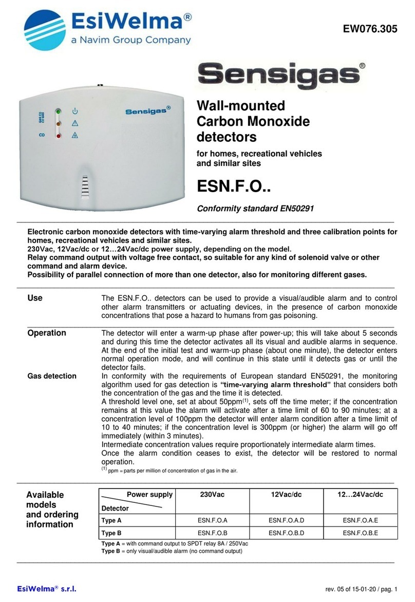
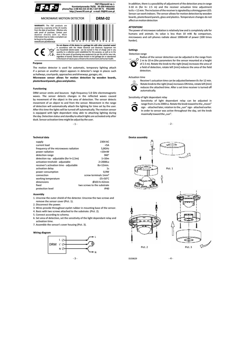
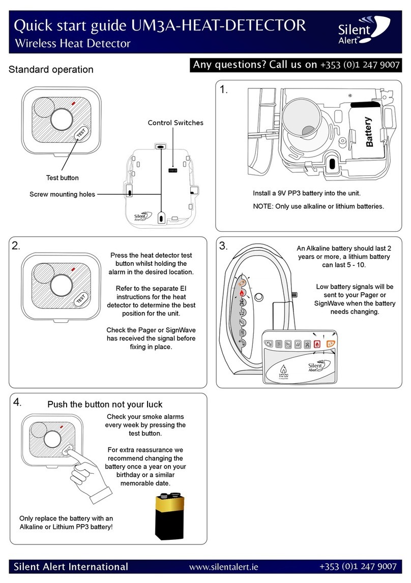
The BlocD8 is an eight block occupancy
detector for DCC. It is particularly useful
where high density or centrally located
detection is desired. Yards and automatic
train control are some examples. It provides
complete isolation from the track by using
transformer type sensors. This also means
there is no drop in track voltage as there is
with sensing diodes. The BlocD8 is designed
to work well with the family of SIC24 Signal
and Indicator Controllers and the CSC
Central Signal Controller. The BlocD8 can be
in a stand-alone mode with using the output
connector or in a network with other devices
using the serial bus.
TEAM DIGITAL, LLC
3111 Timber Valley Dr
Kokomo IN 46902
www.teamdigital1.com
08.30.17
BlocD8
1
1
8
Status LEDs Sensitivity
Smart
button
Output connector Serial bus
Track
or
DC power

1 Operation!3
2 Getting Started!3
1.1 LED Indicators!4
3 “Smart” Programming!4
4 Configuration Variables (CVs)!4
4.02 Reset the BlocD8 to factory defaults!5
4.1 Output Address!5
4.2 Output Control!5
4.3 Unoccupied Delay !5
4.4 Decoder Configuration!5
4.5 Status Report!5
4.6 Input Control!6
4.7 Route Execute Address!6
4.8 Route Cell Address!6
4.9 Send Address Delay !6
4.10 Operations Mode Loco Address!6
5 Connections!7
5.1 Power!7
5.2 Track Block Sensors!7
5.3 Output Drive!7
5.4 10 PIN Output!7
5.5 Serial Bus!7
6 Applications!7
6.1 Relay drive!7
6.2 Routes!7
7 Summary of Configuration Variables!8
2

1 Operation
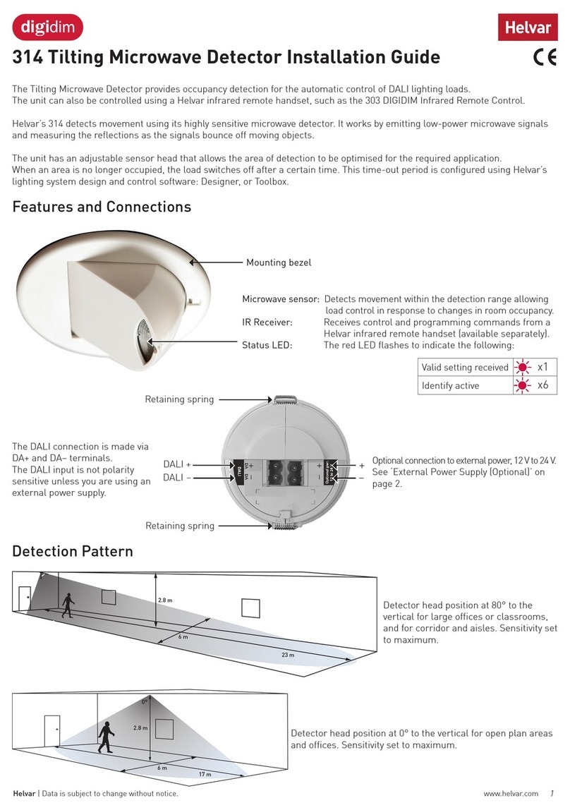
The BlocD8 is capable of sensing current in eight isolated sections of track called blocks. This provides for detecting the
presence of locomotives or other rolling stock that draw current from the track. The status LEDs on the BlocD8 indicate
when a block is occupied. For eternal block
status indication the 10 pin connector and/or
the serial bus can be used.
The track feed wire for one rail of the block
is passed through one of the BlocD8 sensors
before connecting the feeder to the track. All
current flowing to a block must pass through
a detector for proper operation. Do not
power any type of accessory from the track
feeder or there will be false block detection.
Locomotives, lighted cars and rolling stock with resistive wheels sets draw different amounts of current from the track. The
BlocD8 has two potentiometers to adjust sensitivity. Turning the pot CCW will increase the sensitivity. If the pot is turned
fully CCW there may be false block detection. Passing the feed wire through each sensor two times will increase the
sensitivity and can improve reliable detection. See “TIP” in section 2.
Duty track can cause intermittent current flow. A built in filter keeps the BlocD8 from rapidly turning the status indicator off
and on if the current flow is interrupted. This filter also keeps the status indicator on after a train leaves the block for a short
period of time.
The BlocD8 includes a serial bus. If the bus is used the BlocD8 will send a message indicating the status of the related block.
This message is available to any other device on the bus. The default address is 1 to 8 for the eight sensors respectively.
2 Getting Started
The BlocD8 does NOT require the
serial bus to operate. If the serial bus
is NOT used, no programming is
required. Even if the serial bus is used
programming may not be necessary if
only one BlocD8 is used.
The following diagram shows the
BlocD8 detecting three blocks in a
single power district. Since each
detector is completely isolated from
the track and each other, no special
provision is required for the BlocD8 to
be used across several power districts.
The wire that passes through the sensor
should be stranded with a recommend
maximum size of AWG 18. The stiffer
the wire the more likely a sensor could be
damaged. The wire sheathing should not be
removed. In an actual application a terminal
strip can be used to connect the wire that
loops though the sensors to the other wires.
The current sensors used in the BlocD8 are
sensitive to radiated noise that can occur
when high current is flowing through a wire.
For this reason the track power wires to and
from the BlocD8 must be carefully routed.
The diagram shows correct and incorrect ways to route wires. Incorrect routing of wires will cause false block
detection.Wires with DCC current should be routed away from the sensors in a perpendicular manner.
One track block
Track feeder wire
All current to track
Track power
Sensor for one section of BlocD8
Booster
Track
or DC
power
Serial bus
Open collector
outputs
BlocD8
1
1
8
Status LEDs Sensitivity
Smart
button
Sensitivity adjustment
for sensors 1 - 4
Sensitivity adjustment
for sensors 5 - 8
Example of connections
for three blocks
NOTE: turning pot all
the way CCW may give
poor results
Recommended minimum
distance for any parallel
wire ~ 3”
To terminal strip
Correct wire routing
Incorrect wire routing
3

The BlocD8 can be powered from the track or 12 volt DC filtered power supply. See section 5.1 for
more details.
If external LED status indicators are used a separate DC power supply is required as shown.
If more than one BlocD8 is used in a serial bus network then the addresses will have to changes so
there is no duplicates. See section 3, “Smart” Programming. For very custom programming see section
4, Configuration Variables for various options.
1.1 LED Indicators
The status LEDs will all light at power on. Subsequently they will light indicating which block is occupied. The green LED
flashes about ever four seconds indicating normal operation.
3 “Smart” Programming
“Smart” programming is a term used to describe an easy way to program the BlocD8 addresses. The throttle is used to issue
switch or accessory commands just like controlling switches (turnouts).
Programming is only require if the
serial bus (called LocoNet® in a
Digitrax system) is used and the
addresses need to be changed from the
factory settings.
To program in “Smart” mode, connect
the BlocD8 power terminals to track
power. Turn on power. Wait about 5 or
6 seconds.
Press the “Smart” program button and
hold it down for approximately one
second until status LED1 starts to flash.
Then release it. The BlocD8 is now
ready to have the addresses changed.
Using the throttle select the switch
address or accessory number you want
for the start of eight sequential
addresses and issue a throw (reverse)
command. The BlocD8 will reset and
be ready to use with the new addresses.
To program other items start with Section 2 or 3 as show in the Smart
Programming Summary table.
In steps 1 and 2 of section 3 a CV value is programmed instead of an
address. Check the appropriate section in the manual to determine the CV
value and use a switch address for that value.
4 Configuration Variables (CVs)
The BlocD8 supports Paged Mode Programming in Service Mode and Operations (Ops) Mode programming. To program in
paged mode, connect the Track Power terminals to the programming track. See diagram on the front page. When power is
applied, status LED 1 will come on and the green LED will flash when programming is successful. Some systems only apply
power during actual programming, so LED1 will only be on during that time. The BlocD8 does not have built in feedback
like a mobile decoder. Therefore, some systems may show a “no decoder on track” error or “can not read CV”. However it
still is programmed. To enter normal operation, disconnect from the program track and connect as defined is section 5.
12
109
5
DC
Power +-
4
Smart Programming Summary
Smart Programming Summary
Smart Programming Summary
Smart Programming Summary
#Flashes
Description
t
c
Section 1: To start - Press the “Smart” button until LED1 starts to flash
Section 1: To start - Press the “Smart” button until LED1 starts to flash
Section 1: To start - Press the “Smart” button until LED1 starts to flash
Section 1: To start - Press the “Smart” button until LED1 starts to flash
1
Beginning address for 8 sequential addresses
accept
accept
Section 2: To start here - Press the “Smart” button until the green LED lights - Non-sequential addresses
Section 2: To start here - Press the “Smart” button until the green LED lights - Non-sequential addresses
Section 2: To start here - Press the “Smart” button until the green LED lights - Non-sequential addresses
Section 2: To start here - Press the “Smart” button until the green LED lights - Non-sequential addresses
1
Input 1 address
accept
accept
2
Input 2 address
accept
accept
3
Input 3 address
accept
accept
4
Input 4 address
accept
accept
5
Input 5 address
accept
accept
6
Input 6 address
accept
accept
7
Input 7 address
accept
accept
8
Input 8 address
accept
accept
Section 3: To start here - Press the “Smart” button until the green LED lights and then turns off
Section 3: To start here - Press the “Smart” button until the green LED lights and then turns off
Section 3: To start here - Press the “Smart” button until the green LED lights and then turns off
Section 3: To start here - Press the “Smart” button until the green LED lights and then turns off
1
Value of CV9 - Decoder configuration
set
clear
2
Value of CV10 - Status report
set
clear
Switch (Turnout) Terminology
Switch (Turnout) Terminology
Switch (Turnout) Terminology
This manual
throw or t
close or c
Digitrax
throw or t
close or c
NCE
reverse or OFF or 2
normal or ON or 1
Lenz
-
+
MRC
OFF
ON

To program in ops mode hold down the Smart button just before power is turned on. When the green LED turns on release
the button then wait until LED1 turns off. The BlocD8 is now in ops mode until power is turned off. The default ops address
is one (1). This is a loco address, so be careful when using this feature. The BlocD8 can be programmed so it is always in
ops mode by setting option 3 in CV9. When using ops mode to change CV values, the BlocD8 does not recognize some
new values until power is turned off and then back on. Programming CV7 with a value of 1 will restart the BlocD8 so
power need not be cycled when programming in ops mode. This is the same as turning power off and then back on.
4.02 Reset the BlocD8 to factory defaults
To “reset” all CVs to factory defaults, turn power on and wait until all the red LEDs turns off. Then press the “Smart” button
and continue to hold the button down (at least 16 seconds) until a red LED and the green LED are alternately flashing. Also
programming CV7 with a value of 170 in ops mode will “reset” all CV’s to the factory default value.
4.1 Output Address
These CVs determine the address of the outputs and how the output responds. Normally the output indicates the status of it’s
respective block and has the same address.
However, for special applications, each output
can be controlled independent of the input by
assigning a unique address.
Each output has two CVs, an address and a type
which includes the address adder, that makes up
the address. See section 7 for CV numbers. The
type CV also contains the message type the
output responds to. That is, the output will turn
on when a command is received when this
criteria is met. The following table shows the
CV value to set the criteria.
To calculate the type CV value add up the
selected values.
The address is constructed with two CVs, an
address and an address adder. If an address
greater than 255 is needed then the address
adder value will be greater than zero.
Otherwise the address is set by the address
value only.
The address adder value represents a number that is added to the address value to give the required address. The address
adder table shows the CV value to use for the adder. When using “Smart” Programming to change the input (block address),
these get changed also.
4.2 Output Control
See section 4.1 for special control of the outputs. This applies to both the status LEDs and open collector outputs as they are
linked together.
4.3 Unoccupied Delay
CV56 to 63 - Unoccupied delay. Value x 256 ms = delay. Default is 12 (~3 seconds).
These CVs determines how long the BlocD8 waits to show unoccupied after the block actually becomes unoccupied.
4.4 Decoder Configuration
CV9 - Configuration.
This CV determines the configuration which consist of only one option.
Ops Mode Programming. Allows Operations mode (On the Main) programming using a Loco address to be enabled all the
time. Programming this CV to a value of one (1) will set this option. See section 4.10.
4.5 Status Report
CV10 - Status report. Default is one (1).
This CV provides options for sending the state of all
inputs on the serial bus.
Option 1 - Input state messages are sent on the serial bus
at power on.
Option 2 - N/A
Option 3 - Input state messages are sent on the serial bus when a Digitrax interrogation command is received.
5
Output
Output
Output
Address CV
Value
Select
Address
1 - 255
Program this value into the appropriate address CV
Type CV
Value
Select
Close
64
Select
Throw
0
one
Message type, sensor
32
Select
Message type, feedback (actual switch position)
16
Message type, switch (commanded switch position)
0
one
Address adder (see the address adder table for amount to add)
0 - 9
Program this value into the appropriate type CV
Status Report CV
Value
Select
No options
0
Option 1 - Send input state at power on enabled (default)
1
Option 2 - Not used
-
Option 3 - Interrogate input state enabled
4
Program this value into the status report CV
Address Adder
Address Adder
Address Adder
Address Adder
Address Adder
Address Adder
Address Adder
Address Adder
Address Adder
Address Adder
Address Adder
CV Value
0
1
2
3
4
5
6
7
8
9
ADD
0
256
512
768
1024
1280
1536
1792
2048
2304

4.6 Input Control
These CVs determine what action the inputs
will have when a block state changes. Normally
the action causes block status (sensor) messages
to sent. However, for special applications, other
actions can be programmed.
Unless you understand these special features, it
is recommended that they not be changed. Use
“Smart” programming to change addresses.
For each input there is a primary and secondary
address and type. One or two messages can be
sent on the serial bus when a block state
changes. If an address greater than 255 is
needed then use the address adder. The address
adder value represents a number that is added to
the address value to give the ‘actual’ address.
See section 7 for CV numbers.
4.7 Route Execute Address
These CVs determine the top or execute address
of a route. Each top address is completely
independent of an input address. A route is
executed when a message from any source on
the serial bus including those from the BlocD8
or computers matches the top address, message
type and state for that route. When a route is
executed, turnout commands are sent for each
cell containing an address.
4.8 Route Cell Address
These CVs determine the address in a route cell.
When a route is executed all cell addresses are
sent one at a time. For all addresses in a route to
be sent there must be no empty cells between
cells with addresses.
4.9 Send Address Delay
CV11 - Send address time delay, value 0 to 255.
This CV determines the time delay the BlocD8
waits before sending the next address in a route.
Some switch machine drivers require a time delay between switch activation.
The delay is the CV11 value x 0.25 seconds.
4.10 Operations Mode Loco Address
CV1 - Ops mode address, a value of 1 to 127. Default is one (1).
This CV sets the operations mode program address. This address is used ONLY for programming and has NOTHING to do
with normal operation. This allows programming the BlocD8 just like you would a loco in ops mode. This is a loco 2 digit
address and therefore must be unique among locomotive addresses. Ops mode must be enabled to use this address for
programming on the main. The programming track is not required once this address and ops mode is enabled.
TIP: If the “Smart” program button is pressed when power is turned on, ops mode is enable until power is removed. Useful if
you do not want to have ops mode enabled all the time.
6
Input Control
Input Control
Input Control
Address CV
Value
Select
Address
1 - 255
Program this value into the appropriate address CV
Type CV
Value
Select
Invert the normal state
128
Select
Normal state
0
one
Message type, sensor
32
Select
Message type, feedback (actual switch position)
16
Message type, switch (commanded switch position)
0
one
Address adder (see the address adder table for amount to add)
0 - 9
Program this value into the appropriate type CV
Transition CV (Default = 3, use for secondary message)
Value
Select
Send message on change transition
15
Select
Send message on hi to low transition
11
Send message on low to hi transition
7
Disable secondary message
3
One
Program this value into the appropriate transition CV
Route Top (Execute) Address
Route Top (Execute) Address
Route Top (Execute) Address
Address CV
Value
Select
Address
1 - 255
Program this value into the appropriate address CV
Type CV
Value
Select
Close
64
Select
Throw
0
one
Execution type, sensor
32
Select
Execution type, switch (turnout command)
0
one
Address adder (see the address adder table for amount to add)
0 - 9
Program this value into the appropriate type CV
Route Cell Address
Route Cell Address
Route Cell Address
Address CV
Value
Select
Address
1 - 255
Program this value into the appropriate address CV
Type CV
Value
Select
Close
64
Select
Throw
0
one
Address adder (see the address adder table for amount to add)
0 - 9
Program this value into the appropriate type CV
Delay between sending route addresses
Delay between sending route addresses
Delay between sending route addresses
Delay between sending route addresses
Delay between sending route addresses
Delay between sending route addresses
Delay between sending route addresses
Delay between sending route addresses
Delay between sending route addresses
CV11 Value
0
1
2
4
8
12
16
20
Delay (sec)
0
0.25
0.5
1
2
3
4
5

5 Connections
5.1 Power
The BlocD8 can be powered from the track (16 volts max) or a filtered DC voltage (12 VDC, 35mA) power supply. Most
analog 'Power Packs' will not work because they do not provide smooth (filtered) DC power. The BlocD8 power connector is
non polarized and either terminal can be connected to plus or minus of the DC power supply. The power supply should be
isolated from the system ground. That is, not connected to ground (booster ground, house wiring ground, etc). When multiple
BlocD8 s are used they can be all connected to one power supply. The power supply must be able to supply the current for all
the BlocD8s. The plus and minus of the power supply must be connected to the same power power terminal on each BlocD8.
5.2 Track Block Sensors
There is no electrical connection to the sensors. They are completely isolated. They have a hole in them to pass a wire that
carries the track current. See diagram in section 1. Maximum of one pass if the sensor is labeled PE-51687. Maximum
continuous current 3 amps.
5.3 Output Drive
The outputs are open collector and can drive LEDs and other low current devices such as low current relays. Maximum
current is 50 mA.
5.4 10 PIN Output
Connections can be made using our terminal strip adapter (TSA) or our Connector Cable Kit. You can build
your own by using flat ribbon cable Insulation Displacement (IDC) and connectors from Jameco. The mating
connector is #138376. 10 ft of multicolor flat ribbon cable is #639672. Pins 1-4 are outputs for detectors 1-4.
Pins 7-10 are outputs for detectors 5-8. See the diagram on the front page for connector location.
5.5 Serial Bus
The BlocD8 has two RJ12 connectors for ease in
making connections between devices. In a Digitrax
system the data pins are LocoNet® and the RS pins are
Rail Sync. RS is not used by the BlocD8. In a systems
when more than 10 Team Digital devices with a serial
bus are used the bus terminating resistor lead should be
cut on any additional devices.
Warning: This bus IS NOT compatible with other systems 6 pin connectors i.e. NCE, MRC etc.
6 Applications
6.1 Relay drive
The BlocD8 outputs can drive a relay with a low current coil. The relay shown has a coil
current of 30 mA and a contact rating of 10 amps (Digikey PB380-ND). A clamping diode
(1N4148) is required when driving a relay to suppress the voltage spike. Example shows
relay connected to output 2, pin 2.
6.2 Routes
The BlocD8 supports eight routes which
requires the use of the serial bus. Each
route has eight cells. There is one top or
route execution address for each route.
A route can be executed by a block
sensor or switch type message. When
using a block sensor message several
turnouts can automatically be alined
went a block becomes occupied.
Multiple routes can be executed be
having more than one top address the
same address. Also a route can execute
from other routes (nested). This occurs
when a route cell has an address that
matches the top address of another route.
Warning: Do not create recursive loops.
That is, do not have a route executing
itself or two routes executing each other.
Otherwise various unexplained problems will occur. The diagram shows an example of five routes using four switches. The
route CV values were determined using the information in sections 4.6 and 4.7.
1
210
9
Terminating
Resistor
Data
GrounGround
Data
RS RS
12
109
5
- minus + 12V
SW 33
SW 34
SW 35
SW 36
Route 1 (SW 33 -t, SW 36 - c)
Route 2 (SW 33 -t, SW 36 - t)
Route 3 (SW 33 - c, SW 34 - c)
Route 4 (SW 33 - c, SW 34 - t, SW 35 -t)
Route 5 (SW 33 - c, SW 34 - t, SW 35 - c)
Yard diagram
7
Cables are wired pin 1to pin 1
Route Example
Route Example
Route Example
Route Example
Route Example
Route Example
Route Example
Route Example
Route Example
Route
1
2
3
4
5
6
7
8
Execute address
101 t
101 c
102 t
102 c
103 t
Address 1
33 t
33 t
33 c
33 c
33 c
Address 2
36 c
36 t
34 c
34 t
34 t
Address 3
35 t
35 c
Address 4
Address 5
Address 6
Address 7
Address 8

7 Summary of Configuration Variables
CV#
Function/Default Value
CV#
Function/Default Value
CV#
Function/Default Value
1
Ops Mode Loco Address
1
60
Input 5 delay x 256 ms
12
119
Route 4 Top Address Adder
0
2
reserved
-
61
Input 6 delay x 256 ms
12
120
Route 5 Top Address
0
3
reserved
-
62
Input 7 delay x 256 ms
12
121
Route 5 Top Address Adder
0
4
reserved
-
63
Input 8 delay x 256 ms
12
122
Route 6 Top Address
0
5
reserved
-
64
Output 1 Address
1
123
Route 6 Top Address Adder
0
6
reserved
-
65
Output 1 Type & Address Adder
32
124
Route 7 Top Address
0
7
Manufacturer Version No.
-
66
reserved
-
125
Route 7 Top Address Adder
0
8
Manufacturer ID
25
67
Output 2 Address
2
126
Route 8 Top Address
0
9
Decoder Configuration
0
68
Output 2 Type & Address Adder
32
127
Route 8 Top Address Adder
0
10
Status Report
1
69
reserved
-
128
Route 1 Cell 1 Address
0
11
Route send delay
0
70
Output 3 Address
3
129
Route 1 Cell 1 Address Adder
0
12
reserved
-
71
Output 3 Type & Address Adder
32
130
Route 1 Cell 2 Address
0
13
reserved
-
72
reserved
-
131
Route 1 Cell 2 Address Adder
0
14
reserved
-
73
Output 4 Address
4
132
Route 1 Cell 3 Address
0
15
reserved
-
74
Output 4 Type & Address Adder
32
133
Route 1 Cell 3 Address Adder
0
16
Input 1 Address
1
75
reserved
-
134
Route 1 Cell 4 Address
0
17
Input 1 Type & Address Adder
160
76
Output 5 Address
5
135
Route 1 Cell 4 Address Adder
0
18
Input 1 Transition
3
77
Output 5 Type & Address Adder
32
136
Route 1 Cell 5 Address
0
19
Input 1 Secondary Address
0
78
reserved
-
137
Route 1 Cell 5 Address Adder
0
20
Input 1 Sec Type & Address Adder
0
79
Output 6 Address
6
138
Route 1 Cell 6 Address
0
21
Input 2 Address
2
80
Output 6 Type & Address Adder
32
139
Route 1 Cell 6 Address Adder
0
22
Input 2 Type & Address Adder
160
81
reserved
-
140
Route 1 Cell 7 Address
0
23
Input 2 Transition
3
82
Output 7 Address
7
141
Route 1 Cell 7 Address Adder
0
24
Input 2 Secondary Address
0
83
Output 7 Type & Address Adder
32
142
Route 1 Cell 8 Address
0
25
Input 2 Sec Type & Address Adder
0
84
reserved
-
143
Route 1 Cell 8 Address Adder
0
26
Input 3 Address
3
85
Output 8 Address
8
144
Route 2 Cell 1 Address
0
27
Input 3 Type & Address Adder
160
86
Output 8 Type & Address Adder
32
145
Route 2 Cell 1 Address Adder
0
28
Input 3 Transition
3
87
reserved
-
146
Route 2 Cell 2 Address
0
29
Input 3 Secondary Address
0
88
reserved
-
147
Route 2 Cell 2 Address Adder
0
30
Input 3 Sec Type & Address Adder
0
89
reserved
-
148
Route 2 Cell 3 Address
0
31
Input 4 Address
4
90
reserved
-
149
Route 2 Cell 3 Address Adder
0
32
Input 4 Type & Address Adder
160
91
reserved
-
150
Route 2 Cell 4 Address
0
33
Input 4 Transition
3
92
reserved
-
151
Route 2 Cell 4 Address Adder
0
34
Input 4 Secondary Address
0
93
reserved
-
152
Route 2 Cell 5 Address
0
35
Input 4 Sec Type & Address Adder
0
94
reserved
-
153
Route 2 Cell 5 Address Adder
0
36
Input 5 Address
5
95
reserved
-
154
Route 2 Cell 6 Address
0
37
Input 5 Type & Address Adder
160
96
reserved
-
155
Route 2 Cell 6 Address Adder
0
38
Input 5 Transition
3
97
reserved
-
156
Route 2 Cell 7 Address
0
39
Input 5 Secondary Address
0
98
reserved
-
157
Route 2 Cell 7 Address Adder
0
40
Input 5 Sec Type & Address Adder
0
99
reserved
-
158
Route 2 Cell 8 Address
0
41
Input 6 Address
6
100
reserved
-
159
Route 2 Cell 8 Address Adder
0
42
Input 6 Type & Address Adder
160
101
reserved
-
160
Route 3 Cell 1 Address
0
43
Input 6 Transition
3
102
reserved
-
161
Route 3 Cell 1 Address Adder
0
44
Input 6 Secondary Address
0
103
reserved
-
162
Route 3 Cell 2 Address
0
45
Input 6 Sec Type & Address Adder
0
104
reserved
-
163
Route 3 Cell 2 Address Adder
0
46
Input 7 Address
7
105
reserved
-
164
Route 3 Cell 3 Address
0
47
Input 7 Type & Address Adder
160
106
reserved
-
165
Route 3 Cell 3 Address Adder
0
48
Input 7 Transition
3
107
reserved
-
166
Route 3 Cell 4 Address
0
49
Input 7 Secondary Address
0
108
reserved
-
167
Route 3 Cell 4 Address Adder
0
50
Input 7 Sec Type & Address Adder
0
109
reserved
-
168
Route 3 Cell 5 Address
0
51
Input 8 Address
8
110
reserved
-
169
Route 3 Cell 5 Address Adder
0
52
Input 8 Type & Address Adder
160
111
reserved
-
170
Route 3 Cell 6 Address
0
53
Input 8 Transition
3
112
Route 1 Top Address
0
171
Route 3 Cell 6 Address Adder
0
54
Input 8 Secondary Address
0
113
Route 1 Top Address Adder
0
172
Route 3 Cell 7 Address
0
55
Input 8 Sec Type & Address Adder
0
114
Route 2 Top Address
0
173
Route 3 Cell 7 Address Adder
0
56
Input 1 delay x 256 ms
12
115
Route 2 Top Address Adder
0
174
Route 3 Cell 8 Address
0
57
Input 2 delay x 256 ms
12
116
Route 3 Top Address
0
175
Route 3 Cell 8 Address Adder
0
58
Input 3 delay x 256 ms
12
117
Route 3 Top Address Adder
0
176
Route 4 Cell 1 Address
0
59
Input 4 delay x 256 ms
12
118
Route 4 Top Address
0
177
Route 4 Cell 1 Address Adder
0
8

CV#
Function/Default Value
CV#
Function/Default Value
178
Route 4 Cell 2 Address
0
220
Route 6 Cell 7 Address
0
179
Route 4 Cell 2 Address Adder
0
221
Route 6 Cell 7 Address Adder
0
180
Route 4 Cell 3 Address
0
222
Route 6 Cell 8 Address
0
181
Route 4 Cell 3 Address Adder
0
223
Route 6 Cell 8 Address Adder
0
182
Route 4 Cell 4 Address
0
224
Route 7 Cell 1 Address
0
183
Route 4 Cell 4 Address Adder
0
225
Route 7 Cell 1 Address Adder
0
184
Route 4 Cell 5 Address
0
226
Route 7 Cell 2 Address
0
185
Route 4 Cell 5 Address Adder
0
227
Route 7 Cell 2 Address Adder
0
186
Route 4 Cell 6 Address
0
228
Route 7 Cell 3 Address
0
187
Route 4 Cell 6 Address Adder
0
229
Route 7 Cell 3 Address Adder
0
188
Route 4 Cell 7 Address
0
230
Route 7 Cell 4 Address
0
189
Route 4 Cell 7 Address Adder
0
231
Route 7 Cell 4 Address Adder
0
190
Route 4 Cell 8 Address
0
232
Route 7 Cell 5 Address
0
191
Route 4 Cell 8 Address Adder
0
233
Route 7 Cell 5 Address Adder
0
192
Route 5 Cell 1 Address
0
234
Route 7 Cell 6 Address
0
193
Route 5 Cell 1 Address Adder
0
235
Route 7 Cell 6 Address Adder
0
194
Route 5 Cell 2 Address
0
236
Route 7 Cell 7 Address
0
195
Route 5 Cell 2 Address Adder
0
237
Route 7 Cell 7 Address Adder
0
196
Route 5 Cell 3 Address
0
238
Route 7 Cell 8 Address
0
197
Route 5 Cell 3 Address Adder
0
239
Route 7 Cell 8 Address Adder
0
198
Route 5 Cell 4 Address
0
240
Route 8 Cell 1 Address
0
199
Route 5 Cell 4 Address Adder
0
241
Route 8 Cell 1 Address Adder
0
200
Route 5 Cell 5 Address
0
242
Route 8 Cell 2 Address
0
201
Route 5 Cell 5 Address Adder
0
243
Route 8 Cell 2 Address Adder
0
202
Route 5 Cell 6 Address
0
244
Route 8 Cell 3 Address
0
203
Route 5 Cell 6 Address Adder
0
245
Route 8 Cell 3 Address Adder
0
204
Route 5 Cell 7 Address
0
246
Route 8 Cell 4 Address
0
205
Route 5 Cell 7 Address Adder
0
247
Route 8 Cell 4 Address Adder
0
206
Route 5 Cell 8 Address
0
248
Route 8 Cell 5 Address
0
207
Route 5 Cell 8 Address Adder
0
249
Route 8 Cell 5 Address Adder
0
208
Route 6 Cell 1 Address
0
250
Route 8 Cell 6 Address
0
209
Route 6 Cell 1 Address Adder
0
251
Route 8 Cell 6 Address Adder
0
210
Route 6 Cell 2 Address
0
252
Route 8 Cell 7 Address
0
211
Route 6 Cell 2 Address Adder
0
253
Route 8 Cell 7 Address Adder
0
212
Route 6 Cell 3 Address
0
254
Route 8 Cell 8 Address
0
213
Route 6 Cell 3 Address Adder
0
255
Route 8 Cell 8 Address Adder
0
214
Route 6 Cell 4 Address
0
215
Route 6 Cell 4 Address Adder
0
216
Route 6 Cell 5 Address
0
217
Route 6 Cell 5 Address Adder
0
218
Route 6 Cell 6 Address
0
219
Route 6 Cell 6 Address Adder
0
WARNING: This product contains a chemical known to thestate of
California to cause cancer, birth defects or other reproductive harm.
9
Table of contents
Popular Security Sensor manuals by other brands
Dwyer Instruments
Dwyer Instruments CDTA-2E000 Installation and operating instructions

ActSafe
ActSafe ACC II Ascender user manual
Fastus
Fastus BGS-HL Series instruction manual

Hokuyo
Hokuyo UGM-50LXP manual

Newton Security
Newton Security T-DAR T1000 Installation and operation manual

Guardall
Guardall Vega DX installation instructions


