manuals.online logo
Brands
  1. Home
  2. •
  3. Brands
  4. •
  5. HELVAR
  6. •
  7. Security Sensor
  8. •
  9. HELVAR 314 Tilting User manual

HELVAR 314 Tilting User manual

1
Helvar | Data is subject to change without notice. www.helvar.com
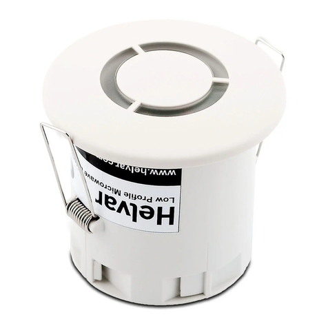
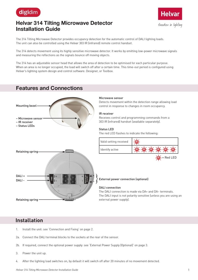
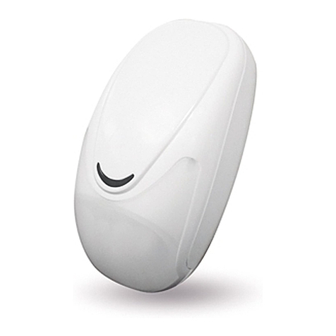
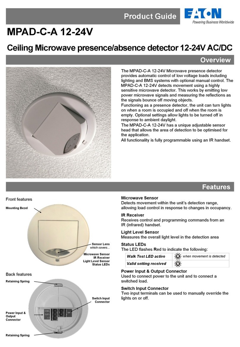
The Tilting Microwave Detector provides occupancy detection for the automatic control of DALI lighting loads.
The unit can also be controlled using a Helvar infrared remote handset, such as the 303 DIGIDIM Infrared Remote Control.
Helvar’s 314 detects movement using its highly sensitive microwave detector. It works by emitting low-power microwave signals
and measuring the reflections as the signals bounce off moving objects.
The unit has an adjustable sensor head that allows the area of detection to be optimised for the required application.
When an area is no longer occupied, the load switches off after a certain time. This time-out period is configured using Helvar’s
lighting system design and control software: Designer, or Toolbox.
314 Tilting Microwave Detector Installation Guide
Features and Connections
Microwave sensor: Detects movement within the detection range allowing
load control in response to changes in room occupancy.
IR Receiver: Receives control and programming commands from a
Helvar infrared remote handset (available separately).
Status LED: The red LED flashes to indicate the following:
Mounting bezel
Valid setting received x1
Identify active x6
The DALI connection is made via
DA+ and DA– terminals.
The DALI input is not polarity
sensitive unless you are using an
external power supply.
Optional connection to external power, 12 V to 24 V.
See
‘External Power Supply (Optional)’ on
page 2.
Retaining spring
Retaining spring
DALI +
DALI
-
+
-
Detection Pattern
Detector head position at 80° to the
vertical for large offices or classrooms,
and for corridor and aisles. Sensitivity set
to maximum.
2.8 m
80°
6 m
23 m
Detector head position at 0° to the vertical for open plan areas
and offices. Sensitivity set to maximum.
2.8 m
0°
17 m
6 m
2Helvar 314 Tilting Microwave Detector: Installation Guide
Surface back box SBB-B
93mm
82mm
85mm
60mm
51mm
Fixing screw
1.
4.
• Position the detector so that the occupants of the room are normally inside the detection zone.
• Do not install the detector within 1 m of any lighting, forced air heating, or ventilation equipment.
• Do not fix the detector to an unstable or vibrating surface.
• Install the unit as far away as possible from the surface of metal objects.
• The detection pattern illustrated (see ‘Detection Pattern’ on page 1) is based on a mounting height of 2.8 m. A lower
mounting height will decrease the overall size of the detection zone.
Prerequisites
Installation
Connection, Fitting and Set Up
Connect the DALI
terminal blocks.
If required, connect the
external power cable.
External Power Supply (Optional)
The table below shows the various 12 V to 24 V external
power supply units that can be used and the sensor
hardware revision needed for each of them.
EPS Current
limited
Link from
DA– to EPS–
Sensor hardware
revision
Helvar 401 Yes No Any
Helvar 402 Yes Yes Any
Helvar 403 Yes No Any
Helvar
LL1x30-E-CV24 Slow No 4 or later
Generic
12 V to 24 V No No* 4 or later
Note:In some cases the generic EPS output is referenced to earth.
With some models, you must make a wire
link between the DALI negative terminal
and the negative terminal of the external
power supply, as shown in the figure.
+
-
+
-
2.
Attach the cable clamp.
Insert the detector into the
cutout. Take special care when
bending the springs back
3. Ø 78 mm
Ensure the fitted unit sits flush
to the ceiling.
4.
With the circuit switched on the
LED in the sensor will flash red
for 30 seconds.
When the detector is activated the relating light load will
illuminate and remain on for a defaulted time of 20 minutes if
there is no other movement detected.
Check the DALI network connection by selecting the Identify function
in Designer or Toolbox
Adjustments to the detector such as sensitivity, On / Off transitions
and illumination periods can be managed using Designer or Toolbox.
Note: Maximum sensitivity makes the detector unit extremely sensitive
to movement and may detect through glass, thin walls or partitions. If this
causes a problem, reduce the sensitivity.
When using Designer, connect the PC to the lighting network via a
Helvar router.
When using Toolbox, connect the PC to the lighting network via a
Helvar serial or USB interface.
For information about Designer and Toolbox, visit www.helvar.com.
51mm 82mm
85mm
93mm
60mm
3
Helvar | Data is subject to change without notice. www.helvar.com
Technical Data
Dimensions (mm)
3.5 3.5
92⌀ 85
78
70
Connections
External power / DALI: Removable terminal block
Wire section: 0.5 mm²– 1.5mm² solid or stranded
Cable rating: All cables must be mains rated.
Power
DALI supply input: 13 V to 22.5 V
DALI consumption: 40 mA Note: DALI consumption is less than 2
mA when external power is supplied to the unit.
(Optional) External power:12 V to 24 V; 0.5 W
Remote control functions
Use Helvar infrared
remote handsetto:
Recall lighting scenes 1–4, Adjust
light levels, Store current level, Install
preset levels for scenes 1–4.
Note: Adjust sensitivity using Designer, or Toolbox
(not by remote control unit).
Factory setting for sensor sensitivity: 9 (maximum).
Microwave operating frequency
Model Frequency
314 10.687 GHz - China, Hong Kong, India, Malaysia,
Middle East, Singapore, United Kingdom
314/R2 10.525 GHz - Australia, Europe except for
Austria, France, Germany, Ireland, Portugal,
Slovakia, Switzerland, United Kingdom
314/R3 9.900 GHz - France, Portugal, Switzerland
Mechanical data
Mounting hole diameter: 78 mm
Bezel diameter: 85 mm
Recommended clearancedepth
(incl. 50mm for cabling):
80 mm (without protective cover)
100 mm (with protective cover)
Material (casing): Flame retardant ABS andPC/ABS
Finish / Colour: Matt / White RAL 9003
Weight: 124 g
IP code: IP30
Operating conditions
Ambient temperature: 0 °C to +50 °C
Relative humidity: Max. 90 %, noncondensing
Storage temperature: –10 °C to +70 °C
Conformity and standards
EMC immunity: EN 61000-6-1
EMC emission: EN 61000-6-3
Safety: EN 60730-1
Environment: Complies with WEEE andRoHS directives.
Version information
Software version: 6
Hardware version: Rev. 4
Software compatibility
Designer: 4.1 or later
Toolbox: 2.2.16 or later
Carefully remove the
metal locking clip,
circled left, from
rear of unit.
Adjust the head to its
required position.
Push the locking clip into
its position, as shown left,
to lock the head. Ensure
the clip is fully secured in
place.
Head Adjustment and Locking
The 303 DIGIDIM Infrared Remote Control can send signals
to the 314 Detector to:
– Recall lighting scenes 1–4.
– Adjust light levels.
– Store current level.
– Install preset levels for scenes 1–4.
For more details visit Helvar.com or speak to one of our
representatives.
1. 2.
Remote Control
Helvar Ltd
Hawley Mill
Hawley Road
DARTFORD
DA2 7SY
UNITED KINGDOM
www.helvar.com
?
Doc. 7860269, issue 11,
2021-03-15
Other HELVAR Security Sensor manuals

HELVAR 318 User manual

HELVAR

HELVAR 318 User manual

HELVAR Digidim 311 User manual

HELVAR

HELVAR Digidim 311 User manual

HELVAR 311 User manual

HELVAR

HELVAR 311 User manual

HELVAR Digidim 313 User manual

HELVAR

HELVAR Digidim 313 User manual

HELVAR digidim 319 User manual

HELVAR

HELVAR digidim 319 User manual

HELVAR Digidim 317 User manual

HELVAR

HELVAR Digidim 317 User manual

HELVAR digidim 314 User manual

HELVAR

HELVAR digidim 314 User manual

HELVAR OB-1501 User manual

HELVAR

HELVAR OB-1501 User manual

HELVAR digidim 317 User manual

HELVAR

HELVAR digidim 317 User manual

HELVAR digidim 313 User manual

HELVAR

HELVAR digidim 313 User manual

Popular Security Sensor manuals by other brands

Abus 4043158057744 manual

Abus

Abus 4043158057744 manual

Agni AGNI-203 quick start guide

Agni

Agni AGNI-203 quick start guide

DigiSpec VMD-1001 Operation manual

DigiSpec

DigiSpec VMD-1001 Operation manual

Pilz PSEN cs1.1n operating instructions

Pilz

Pilz PSEN cs1.1n operating instructions

STEINEL IS 180 series operating instructions

STEINEL

STEINEL IS 180 series operating instructions

EDTM ShowerGuard RD1661 Operator's manual

EDTM

EDTM ShowerGuard RD1661 Operator's manual

PRASTEL 2PH60C quick start guide

PRASTEL

PRASTEL 2PH60C quick start guide

Olimpia TI 150 operating manual

Olimpia

Olimpia TI 150 operating manual

RKI 35-3001A-09 Operator's manual

RKI

RKI 35-3001A-09 Operator's manual

tau TAU-AC-900-PIVOT installation guide

tau

tau TAU-AC-900-PIVOT installation guide

Elkron TT19AM Installation

Elkron

Elkron TT19AM Installation

steute Ex RC Si 56-3G/D Mounting and wiring instructions

steute

steute Ex RC Si 56-3G/D Mounting and wiring instructions

Sports Radar DT100 instructions

Sports Radar

Sports Radar DT100 instructions

KNX DM KNT 002 instruction manual

KNX

KNX DM KNT 002 instruction manual

Powerfix Profi 97003 Operation and safety notes

Powerfix Profi

Powerfix Profi 97003 Operation and safety notes

Trader ARCTIC OWL OWPIROD quick start guide

Trader

Trader ARCTIC OWL OWPIROD quick start guide

urmet domus VOG 5 User handbook

urmet domus

urmet domus VOG 5 User handbook

Tractel Tracpode Operating and maintenance instructions

Tractel

Tractel Tracpode Operating and maintenance instructions

manuals.online logo
manuals.online logoBrands
  • About & Mission
  • Contact us
  • Privacy Policy
  • Terms and Conditions

Copyright 2025 Manuals.Online. All Rights Reserved.