Newton Security T-DAR T1000 User manual

T-DAR®
Model T1000 and Model T2000
Single Door Two Door
TAILGATING / PIGGYBACKING DETECTION SYSTEM
INSTALLATION AND OPERATION MANUAL
Newton Security Inc.
443 SW 41st Street
Renton, WA. 98055 USA
www.newtonsecurityinc.com Revision 3.0

2
Tailgating/Piggybacking
Access control systems are the heart of most security systems. From
smart cards to fingerprinting and even iris recognition technology, there are
many different systems in place to restrict access to secure areas. But there
is one way to completely bypass every one of these systems -with the simple
act of holding the door open. Some people do this out of politeness, as we
are all taught, while others are unknowingly followed through these secure
doors by unauthorized persons. All access control systems, regardless of the
technology used, are vulnerable to this problem.
T-DAR®Solution
Newton’s patent pending T-DAR®system uses sophisticated three-
dimensional optical imaging to detect Piggybacking and Tailgating through
secure portals. The Newton T-DAR system detects persons and differentiates
them from carts or other objects in or around the secure side of the portal and
then utilities Newton's sophisticated Stereo Machine Vision technology to
identify and tag each human within the field of view of the tracking (overhead)
camera. It maintains that tag on that person so long as he or she (or some
portion of the person) remains in the view of the camera. That information is
than combined with the data provided by the access device, door contacts
and other input data to determine if the tagged person is a legal transit or is
tailgating / piggybacking.
Once the status of a person is determined to not be a legal transit but
to be tailgating or piggybacking, the T-DAR system then actuates any number
of possible results, all controlled and selected from an easy to use User
Interface. These alarms range from local alarm sirens, flashing lights and
voice annunciation through remote alarm, real-time delivery of video of the
event to security forces, activation of internal or existing DVR systems and
physical events such as the locking of other doors to prevent the intruder from
further penetrating the secure area.
When the T-DAR system is used in conjunction with physical barriers
such as security portals, mantraps and security revolving doors, the system
can prevent tailgating/piggybacking as well as detecting and alarming on
those occurrences. In addition to the model described in this manual, other
models of the T-DAR system are available for use in:
Double Doors
Mantraps
Optical Turnstiles
Barrier Arm Turnstiles
Barrier Gates (Wing Style)
Automated Immigration Gates
Elevator Control
Escalator Direction Sensing
Vehicle Tailgate Detection
Vehicle Tracking
People Counting
Waiting Line Tracking
Asset Tracking and Verification
Population Counting
Directional Control
Time and Attendance Tracking

3
Critical Elements for a Successful T-DAR Installation
The T-DAR® system does a superb job of detecting violations of access control
security systems. In order to accomplish this task, the T-DAR requires several
critical elements and/or signals from the door and the access control system as
detailed in this manual. Four of the most important elements are:
1. Valid access grant signals must be immediate. The valid access signal
from the access control system must by occur at the same time or before the
door is unlocked to allow an entry and must have duration of at least 300 ms.
In some instances this may require the use of a timer module to allow for
adequate lock activation time. In all circumstances, if a person crosses the
door threshold prior to the receipt of a valid access grant signal by the T-DAR
unit, that person will cause an alarm by the T-DAR system. Especially in the
case of installations where multiple valid entries are allowed on a single door
open cycle, it is critical to confirm that the valid entry signal is reaching the T-
DAR unit prior to a person crossing the door plane and that a separate signal
for each valid entry is received by the T-DAR unit.
2. Door contact/door position switch signals must be immediate. These
signals must be sent to the T-DAR unit at the same that the door is opened.
Unless it can be verified that the access control system can give immediate
door open signals, the T-DAR unit must have an independent circuit for this
function that allows isolation from the access control system. It is
recommended that mechanical switches of the roller and plunger types be
avoided in favor of magnetic switch door contacts.
3. Adequate and consistent lighting are required for accurate operation of
the T-DAR system. The T-DAR system uses stereo video analysis to
determine three-dimensional characteristics of targets and requires sufficient
lighting to perform this task. Equal and consistent lighting from the ceiling
down allows the system to identify and track targets in all areas of the
detection pattern. Lighting from the sides or the floor is not helpful; in fact it
may detract from system performance. If adequate down lighting is not
currently in place, additional lighting must be added. Invisible (near IR)
lighting is available from Newton.
4. Event cameras on multi-door systems (T-2000) must be powered with ac
(alternating current). This allows the independent video signals to be
synced. Failure to have synced video signals will result in distorted and
unusable event video replay clips. Single door systems (T-1000) may use DC
(direct current) powered event cameras.

4
Tailgating/Piggybacking....................................................................................................2
T-DAR®Solution..............................................................................................................2
Critical Elements for a Successful T-DAR Installation......................................................3
PRODUCT DESCRIPTION..............................................................................................7
General Description ..........................................................................................................7
T-DAR Models Covered In This Manual...........................................................................8
T-1000 Single Head (Single Door) Systems...................................................................8
T-2000 Two Head (2 Independent Doors) Systems........................................................8
T-DAR Models Not Covered In This Manual....................................................................8
T-DAR Product List for the Systems covered by this Manual............................................9
SPECIFICATIONS.............................................................................................................11
CB100/200 Control Unit .................................................................................................11
S100 Annunciator ...........................................................................................................13
DC200LP Stereo Tracking Head .....................................................................................15
I100 Door Position Encoder ............................................................................................17
EC105 Event Camera......................................................................................................19
EA101/EA101A Cable Extender/Amplifier.....................................................................21
INSTALLATION ...............................................................................................................24
Important Safety and Warning Information.....................................................................24
Tips for a Successful T-DAR Installation........................................................................25
Physical Installation........................................................................................................26
Site Considerations..........................................................................................................27
Before You Begin .......................................................................................................28
Local Device Placement..............................................................................................28
Control Unit ................................................................................................................32
Stereo Tracking Head..................................................................................................33
Annunciator Unit.........................................................................................................33
Event Camera..............................................................................................................34
Door Position Sensor (Door Encoder)..........................................................................34
CONNECTION TO ACCESS CONTROL SYSTEMS .......................................................35
Door Valid Access Grant Switch.....................................................................................35
Relay Connections ..........................................................................................................36
CONNECTION TO LAPTOP / LAN..................................................................................38
To Configure the Host TCP/IP Connection......................................................................38
Install the Software .........................................................................................................38
User Interface (UI) Application...................................................................................38
Door Control Unit Application........................................................................................39
Configure Connection.....................................................................................................40
Connecting via Ethernet ..............................................................................................40
To Connect via Serial Ports.............................................................................................41
Connecting via Serial Port...........................................................................................41
Figure 18 -Configure Connection ...............................................................................41
Configuring the T-DAR ..................................................................................................42
Testing the Units.............................................................................................................43
Capturing Events.............................................................................................................43

5
Configuration and Setup of the T-DAR Software................................................................43
USER INTERFACE ...........................................................................................................45
About the T-DAR User Interface Software..........................................................................45
Tab Pages........................................................................................................................45
Figure 20 –File Tab........................................................................................................46
Save Settings...............................................................................................................46
Load Settings ..............................................................................................................47
Exit .............................................................................................................................47
Connection Menu........................................................................................................48
Connect.......................................................................................................................48
Disconnect ..................................................................................................................48
Configure Connection .................................................................................................48
Display........................................................................................................................52
Alarm and Events........................................................................................................53
Event Camera..............................................................................................................53
Setup I/O.........................................................................................................................54
Installer Camera Settings.................................................................................................56
Image Type .................................................................................................................56
Update Now................................................................................................................56
Viewing Window........................................................................................................56
Physical Setup.............................................................................................................57
Camera Calibration .....................................................................................................57
Sensitivity...................................................................................................................57
Detection Sensitivity...................................................................................................57
Cart Sensitivity............................................................................................................58
Crawler Sensitivity......................................................................................................58
Portal Selection...........................................................................................................60
Door Control...............................................................................................................61
Camera Geometry.......................................................................................................62
Important Safety and Warning Information.....................................................................65
Critical elements to maintain a properly operating T-DAR installation............................66
Programming the Annunciator.........................................................................................69
Maintenance....................................................................................................................70
TroubleshootingTroubleshooting guides..........................................................................71
Troubleshooting guides...................................................................................................71
Tips for getting a good image..........................................................................................71
Lighting ..........................................................................................................................71
Problems Communicating with the T-DAR.....................................................................72
Imaging Problems ...........................................................................................................73
All Monitored Events Are Failing ...................................................................................75
DC Input Specifications ..................................................................................................76
DC Output Specifications................................................................................................76
Lower Power Panel Connections.....................................................................................77
Upper Front Panel Connections.......................................................................................78
Lower Front Panel Connections.......................................................................................79
Lower Power Panel Connections.....................................................................................80

6
Connection details...........................................................................................................81
T-DAR Dual Digital Inputs.............................................................................................84
T-DAR Digital Outputs...............................................................................................85
Known Issues and installation Tips..............................................................................90
INDEX ...............................................................................................................................91

7
General Description
Several configurations of the T-DAR Series are available. The models covered in
this manual are all inside systems and have the following features:
♦Confirm only one human for each authorized entry, including multiple
authorizations for each escorted visitor
♦Allows for carts, parcels and other non-human objects
♦Tracking and detection take place even if the portal is open for other
authorized entries and exits
♦Accepts data from virtually any badge or pass system, including biometrics
and Smart ID systems.
♦When a violation occurs, the alarm activates and the event camera records
the violator in real time.
♦Data, time, and pass number used for the authorized passage are recorded
with the event video.
♦Communicates the alarm condition and transmits the recorded video to
central security in real time over a video or digital link.
♦Allows door to swing in either direction.
♦Fully software configurable; easily adapts to virtually any portal.
♦All operating and communication parameters are controlled by a simple
graphical user interface.
♦Easy setup –no special training required

8
T-DAR Models Covered In This Manual
T-1000 Single Head (Single Door) Systems
♦Swing Doors
♦Sliding Doors
♦Folding Doors
♦Open Passageways
♦Some Elevator Systems (External to the Elevator Door) Systems
♦Most Portals (External to the Portal)
T-2000 Two Head (2 Independent Doors) Systems
♦Swing Doors
♦Sliding Doors
♦Folding Doors
♦Open Passageways
♦Some Elevator (External to the Elevator Door) Systems
♦Most Portals (External to the Portal)
T-DAR Models Not Covered In This Manual
♦Double Door Systems
♦Mantrap Systems
♦Gate (Turnstile) Systems
♦Outside Systems
♦Vehicle Systems
♦People Counting Systems
♦Population Counting
♦Elevator Systems (Internal to the Elevator)
♦Thrown Object Detection Systems
♦Escalator Systems
♦Revolving Doors
♦Time and Attendance Tracking
♦Waiting Line Tracking
♦Directional Control Systems
Consult Sales at Newton Security for T-DAR Models and Manuals for systems not
covered in this manual.

9
T-DAR Product List for the Systems covered by this Manual
Please use the following data when contacting your sales representative for
additional components. Special configurations are also available.
Item Model Number
Description
1. 1 Door
Complete T-DAR System T1000 Complete Tailgate Detection
System-with CB100 Control
Unit, 1 DC 200LP Camera
Head, and 1 S100 Annunciator
Unit
2. 2 Door
Complete T-DAR System T2000 Complete Tailgate Detection
System-with CB200 Control
Unit, 2 DC 200LP Camera
Heads, and 2 S100 Annunciator
Unites
3. 1 Door Control Unit
CB100 Single Door Control Unit
4. 2 Door Control Unit
CB200 2 Door Control Unit
5. Stereo Camera Head
DC200LPLP Stereo Camera Unit
6. Annunciator Unit
S100 Wall Mount Annunciator Unit
with Light, Siren and Voice
Alarm
7. Door Position Sensor
I100 Door Position Sensor-Required
for doors where door swing
intrudes into the field of view of
the T-DAR unit (Door swings
into the secure area).
8. Event Camera
EC105 Color Event Imager

10
9. Cable Extender/Amplifier EA101/EA101A
EA101
powered by the
T-DAR unit
EA101A
powered by
plug mounted
power supplt
Cable Extender--Extends the
distance from the door to the
T-DAR Control Unit for more
than the standard 200’.
Extends the cable length for
the DC200LPLP Stereo
Camera Head, the S100
Annunciator Unit and the I100
Door Position Indicator.
EA101 units can be combined
for up to 1,000’ from the door
to the T-DAR Control Unit.
10. Ceiling Mount Kit Installs DC200LPLP into Drop
Ceiling Panels
11. Wall Bracket
WB100 Stereo Camera Head wall
mounting bracket-used for
mounting a DC200LPLP to a
flat wall
12. Thrown Object Detection
Software F102 Option to detect thrown
objects up to 60 Miles Per
hour
13. Anti-Pass Back Software F103 Option to determine if persons
with a valid access signal have
proceeded through the portal
14. Non-standard I/O Software F104 Customer specified I/O
differing from the standard T-
DAR software
15. Non-standard Operating
Software F105 Customer specified Operating
software differing from the
standard T-DAR operating
software
16. Authorized Cart Software F106 Software allowing specific
individuals to move special
carts though the T-DAR
system or that allows specific
Authorized Carts to be
recognized and to pass though
the T-DAR system

11
CB100/200 Control Unit
Figure 1-T-DAR Control Unit
Size: 6.77” x 16.38” x 12.20”
Weight: 26 lbs.
Enclosure: Bent steel, completely enclosed with door.
Mounting: Mounting via 4 x 1/4 " holes on back panel tabs. (Optional mounting
brackets available)
Standard Operating Temperature: 40 to 110 degrees F, (optional high and low
temperature systems available)
Storage Temperature: 0 to 125 degrees
Power Considerations
The T-DAR Systems requires relatively stable AC power. If the system is installed in
an area where the AC power is not stable and is subject to severe fluctuations
and/or discontinuity, the use of an Uninterruptible Power Supply may be required.
Input Voltage/Current 115/230 VAC 50-60Hz 10A @ 115VAC
Inputs 8 Opto-isolated digital
Outputs 6 Relays 3A each
Video out NTSC or PAL (Software Selectable)
Connectors Phoenix style, BNC (RG-59Uand RJ45)
Serial Connections 2

12
Figure 2-T-DAR Control Unit CAD

13
S100 Annunciator
Figure 3-T-DAR Annunciator
Size: 6.00” x 8.13” x 7.19”
Weight: 5 lbs.
Enclosure: Bent steel, with high impact plastic indicator.
Mounting: Mounting via 4 x 3/16" holes on back panel tabs.
Standard Operating Temperature: 40 to 125 degrees F, (optional high and low
temperature systems available)
Storage Temperature: 0 to 150 degrees F
Input Voltage/Current 12VDC 2A maximum (Powered by the
CB200 Control Unit)
Inputs RJ45 Std. Ethernet Cable from Control
Unit
Speaker Volume Control Rotary Control with front panel access
Illuminator Xenon Strobe w/red colored diffuser

14
Figure 4-T-DAR Annunciator CAD

15
DC200LP Stereo Tracking Head
Figure 5-T-DAR Stereo Tracking Head
Size: 7.00” x 2.50” x 2.50”
Weight: 2.2 lbs.
Enclosure: Bent steel.
Mounting: Mounting via 4 x 1/8" holes on back panel tabs. (Optional mounting
brackets available)
Standard Operating Temperature: 40 to 125 degrees F, (optional high and low
temperature systems available)
Storage Temperature: 0 to 150 degrees F
Input Voltage/Current 12VDC 1A maximum (Powered by the
CB100/200 Control Unit)
Inputs 1-RJ45 Std. Ethernet from Control Unit
Outputs NTSC or PAL Stereo Video (Specify)
Video Connectors BNC x2 (RG-59U)
Focus and Field of View
Factory fixed, non-adjustable
(Correct part number must be specified
for the application camera height.
Consult the table on Page 38 for the lens
specification and part number)
Lighting Both Visible and Near IR (Invisible to
human eyes) DC200 camera heads are
available

16
Figure 6-T-DAR Stereo Tracking Head

17
I100 Door Position Encoder
Figure 7–T-DAR Door Encoder
Size: 2.40” x 2.50” x 2.40”
Weight: 13.5 ounces.
Enclosure: Bent Steel.
Mounting: Mounting via 4 x 1/4-" holes on back panel (Optional mounting brackets
available)
Standard Operating Temperature: 40 to 125 degrees F, (optional high and low
temperature systems available)
Storage Temperature: 0 to 150 degrees F
Input Voltage/Current 12VDC 500mA maximum (Powered by
the CB100/200 Control Unit)
Inputs RJ45 Std. Ethernet from Control Unit
Outputs Quadrature digital output

18
F
igure 8–T-DAR Door Encoder

19
EC105 Event Camera
Figure 9–T-DAR Event Camera
Size: 2.13” x 1.81 x 2.36
Weight: 10 Ounces.
Enclosure: Extruded Aluminum.
Mounting: Mounting via 1 ¼-20 indexed threaded hole on top cover (Optional
mounting brackets available)
Standard Operating Temperature: 40 to 125 degrees F, (optional high and low
temperature systems available)
Storage Temperature: 0 to 125 degrees F
Input Voltage/Current 12VDC/24VAC .5A
Inputs 12 DC or 24VAC Screw Terminals
Note: For 2 door systems, event
cameras must be AC powered to allow
Linelock between cameras
Outputs NTSC or PAL Video (Customer
Specified)
Video Connector BNC (RG-59U)
Focus User adjustable
Lens Supplied without Lens (Unit requires CS
mount lens) Lenses are available from
Newton-specify at time of order

20
Figure 10 –T-DAR Event Camera
This manual suits for next models
1
Table of contents
Other Newton Security Security Sensor manuals
Popular Security Sensor manuals by other brands

Lutron Electronics
Lutron Electronics FC-2601 Operation manual
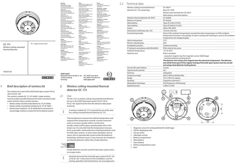
GEZE
GEZE GC 173 Supplementary sheet
Jamara
Jamara LiPo Save Audio LED Instruction
Nittan
Nittan Evolution EVC-H Series instruction manual
Inficon
Inficon Contura S600 Translation of the original operating instructions
ADEC Technologies
ADEC Technologies TDC3 F-F-31 Series Quick reference guide
