Team TS-9M User manual

Bedienungsanleitung
Operating Instruction
Manual de Instrucción
Manuale d’istruzioni
Mode d’emploi
Handleiding
- Full Multi Norm
DE, PL, EC, EU, EI, UK
- EC CEPT
TS-9M
CB-Mobilfunkgerät
CB Mobile Radio
Transmisor móvil CB
Cb émetteur récepteur
Ricetrasmettitori
CB mobile zender
12 Volt
ts-9m_manual_2:RoadCOM manual.qxd 05.09.2011 13:11 Seite 1
3
12
11
8
10
4
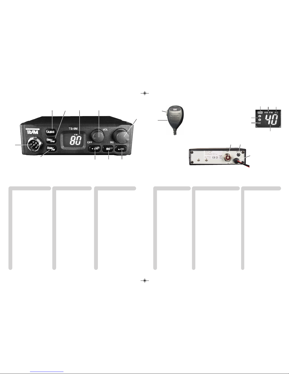
1 Micrófono con cable rizado y
conector 6 pin
2 Botón pulsar para hablar [ PTT ]
3 Indicador LCD
3A SC exploración de canal
3B H/L AM potencia de salida
3C TX modo de transmisión
3D número de canal
3E modo de modulación AM/FM
3F AQ silenciador automático
4 Selección de modulación [ AM/FM ]
5 Botón de selector canal abajo [ q]
6 Botón de selector canal arriba [ p]
7 Botón de Squelch automático [ ASQ ]
8 Interruptor de Squelch manual [ SQ ]
9 Control de volumen, Encendido/
Apagado
10 scan [ SC ]
11 Botón de prioridad canal 9 / 19
[ CH9 / 19 ]
12 Conector de micrófono 6 pin
( GDCH estándar)
13 Conector de antena aéreo
SO239
14 Cable de alimentación DC
15 Conector Jack ( 3,5 mm ) para
altavoces externos
Español página 24 - 29 Netherland pagina 42 - 47
1 Microfoon met spiraal kabel
en 6 pin plug
2 Push to talk toets [ PTT ]
3 LCD display
3A SC kanalen zoeken
3B H/L AM zendvermogen
3C TX mode ontvangst
3D kanaalnummer
3E mode modulatie AM/FM
3F AQ automatische ruisonderdrukking
4 Omschakelen van de
modulatie [ AM/FM ]
5 Kanaal selectie omhoog [ q]
6 Kanaal selectie omlaag [ p]
7 automatische squelch [ ASQ ]
8 Squelch bediening [ SQ ]
9 Volume bediening, Aan/Uit
schakelaar [ Off / Vol ]
10 Scan [ SC ]
11 Kanaal 9 / 19 priority toets
[ CH9/19 ]
12 Microfoon aansluiting 6 pin
( GDCH standaard )
13 Antenne aansluiting SO239
14 DC kabel
15 Jack aansluiting ( 3.5 mm )
voor externe luidspreker
1 Mikrofon mit Spiralkabel +
6-Pol Stecker
2 Sendetaste [ PTT ]
3 LCD-Anzeige
3A SC Kanalsuchlauf
3B H/L AM TX-Sendeleistung
3C TX-Sendemodus
3D Kanalanzeige
3E Betriebsart AM/FM
3F AQ Automatische Rauschsperre
4 Modulationsart [ AM/FM ]
5 Kanalwahlschalter runter [ - ]
6 Kanalwahlschalter hoch [ p]
7 auto. Rauschsperre [ ASQ ]
8 manuelle Rauschsperre [ SQ ]
9 Lautstärkeregler / Ein-/Ausschalter
10 Kanalsuchlauf [ SC ]
11 Vorrangkanaltaste für Kanal 9/19
[ CH9/19 ]
12 Mikrofonanschlussbuchse
6polig,GDCH-Norm
13 Antennenanschlussbuchse SO239
14 Stromversorgungskabel
15 Anschlussbuchse für externen
Lautsprecher 3,5 mm
Deutsch Seite 4 - 10
1
2
14
15
1 Microfono con cavo
spiralizzato e spina a 6 Pin
2 Tasto PTT [ PTT ]
3 Display LCD
3A SC esplorazione
3B H/L AM potere della trasmissione
3C modalità TX
3D numero di canale
3E modalità AM/FM
3F AQ squelch automatico
4 Selezione modalità [ AM/FM ]
5 Tasto selettore canale DN [ q]
6 Tasto selettore canale UP [ p]
7 Regolazione Squelch automa-
tico [ ASQ ]
8 Regolazione Squelch [ SQ ]
9 Regolazione volume + inter-
ruttore ON/OFF
10 scan [ SC ]
11 Tasto di canale 9 / 19
prioritario [ CH9/19 ]
12 Presa microfono a 6 Pin
(GDCH standard)
13 Connettore SO239
14 Cavo alimentatore
15 Jack (3,5 mm.) per
altoparlante esterno
Italiano página 30 - 35
1 Microphone avec câble torsadé
et fiche 6 broches
2 Touche d'émission [ PTT ]
3 Afficheur du type LCD
3A SC recherche des canaux
3B H/L AM puissance d’emission
3C TX mode d’émission
3D numéro du canal
3E mode de la modulation AM/FM
3F AQ squelch automatique
4 Touche de commutation du fonctionne-
ment AM/FM [ AM/FM ]
5 Touche de sélection de canaux
vers le bas [ q]
6 Touche de sélection de canaux
vers le haut [ p]
7 Touche du squelch automatique [ ASQ ]
8 Réglage et marche/arrêt du squelch [SQ]
9 Réglage du volume et marche / arrêt
10 Recherche de canaux [ SC ]
11 Touche canal 9 / 19 prioritaire [ CH9/19 ]
12 Prise du microphone 6 broches
( standard GDCH )
13 Connecteur d'antenne SO239
14 Câble d'alimentation
15 Prise jack ( 3,5 mm ) pour un
haut-parleur externe
Français page 36- 41
1 Microphone with curled cable
and 6 pin plug
2 Push to talk key [ PTT ]
3 LCD display
3A SC scan
3B H/L tx-power
3C TX-mode
3D channel no.
3E operation mode AM/FM
3F AQ automatic squelch
4 Modulation [ AM/FM ]
5 channel selector down [ - ]
6 channel selector up [ p]
7 automatic squelch [ ASQ ]
8 manual squelch [ SQ ]
9 volume control / On/Off switch
10 scan [ SC ]
11 Channel 9 / 19 priority key
[ CH9 / 19 ]
12 microphone jack,
6-pin, GDCH
13 Aerial connector SO239
14 DC power cable
15 Jack socket ( 3.5 mm ) for
external speaker
English page 12 - 17
13
3A
3E
3D
3B
3C 3F
56
79
ts-9m_manual_2:RoadCOM manual.qxd 05.09.2011 13:11 Seite 2

Deutsch
Inbetriebnahme des TEAM TS-9M
1) Montage einer CB-Funkantenne
Die Wahl der Antenne und des Montageortes ist von großer Bedeutung für die maximale
Reichweite Ihrer Funkanlage. Die folgenden Kriterien sollten Sie bei der Wahl des Anten-
nenstandortes und der Montage berücksichtigen.
Allgemein gilt:
> Die Antenne muss für den Funkbetrieb auf 27 MHz geeignet sein.
> Der Standort der Antenne sollte möglichst hoch und unverbaut sein.
> Das Antennenkabel muss unbeschädigt, und die Stecker ordnungsgemäß angeschlossen
sein.
> Das Antennenkabel darf nicht zu stark geknickt werden.
> Antennen mit einer größeren mechanischen Länge erzielen bessere Reichweiten.
Bei der Montage von Mobilantennen ist folgendes zu beachten:
> Die Antenne sollte in der Mitte eines größeren Karosserieteils montiert werden.
> Der Antennenfuß von Mobilantennen sollte möglichst guten Kontakt zu einer metallisch gut
leitenden Fläche des Karosseriebleches haben.
Außer der "festen Montage" einer Mobilantenne, bei der ein Loch in die Karosserie Ihres Fahr-
zeuges gebohrt werden muss, gibt es noch weitere Möglichkeiten, z. B. die Dachrinnen- oder
Kofferraumdeckel-Montage, sowie die Befestigung mit Magnetfuß oder Scheibenantenne.
2) Antennenanschluss
Der PL-Stecker (Typ PL259) des Antennenkabels (Koaxialkabel) wird mit der Buchse (13) an
der Geräterückseite verbunden. Für eine einwandfreie Verbindung muss der Überwurf des
Steckers gut festgedreht werden. Ebenso ist auf eine ordentliche Verbindung des Antennen-
kabels mit dem Antennenfuß zu achten. Nicht einwandfreie Verbindungen können zu einem
Defekt des Gerätes führen und die Funkreichweite erheblich verringern. Die Antennenanlage
(nicht im Lieferumfang enthalten) sollte sehr gut an das Funkgerät angepasst sein, ansonsten
wird ein Teil der Sendeleistung an der Antenne reflektiert und nicht abgestrahlt. Das führt
ebenfalls zu einer geringeren Reichweite der Funkanlage. Die Anpassung der Antenne erfolgt
durch Längenabgleich des Antennenstrahlers bzw. seiner Anpassungsvorrichtung auf ein
minimales Stehwellenverhältnis, welches mit einem Stehwellenmessgerät (z.B. TEAM SWR
1180 -) gemessen werden kann. Das Stehwellenmessgerät muss nach der Messung wieder
aus der Antennenleitung entfernt werden.
Deutsch
INHALTSVERZEICHNIS
Inbetriebnahme des TEAM TS-9M
1) Montage einer CB-Funkantenne 5
2) Antennenanschluss 5
3) Montage des Gerätes im Fahrzeug 6
4) Mikrofon 6
5) Stromversorgung 6
Funkbetrieb mit dem TEAM TS-9M
1) Einschalten [ Off / Vol ] 7
2) Rauschsperre [ SQ / ASQ ]7
3) Kanalwahl [ q] [ p]7
4) Umschaltung der Modulationsarten [ AM/FM ] 7 - 8
5) Umschaltung der Normen 8
6) Senden 8
7) Vorrangkanal 9/19 [ CH9/19 ] 8
8) Kanalsuchlauf 9
9) Anzeige AM-Sendeleistung H/L 9
10) Anschlussbuchse für einen externen Zusatzlautsprecher 9
Hinweise
1) Sicherheitshinweis 10
2) Allgemeine Hinweise 10
3) Service 10
4) Konformität 10
5) Entsorgung 10
Kanalfrequenztabelle 18
Technische Daten 19
Schaltpläne 20 - 23
4 5
ts-9m_manual_2:RoadCOM manual.qxd 05.09.2011 13:11 Seite 4

Funkbetrieb mit dem TEAM TS-9M
1) Einschalten [ Off / Vol ]
Zum Einschalten des Gerätes, den Lautstärkeregler ( 9 ) [ Off / Vol ] nach rechts drehen.
Um die Lautstärke optimal anzupassen, sollte der Rauschsperreregler ( 8 ) [ SQ ] fast bis zum
Linksanschlag gedreht werden,bis ein Rauschen ertönt. Stellen Sie nun die gewünschte Laustär-
ke ein.
Alle Einstellungen, die beim Betrieb des Gerätes vorgenommen werden, bleiben nach dem
Ausschalten erhalten.
2) Rauschsperre [ SQ ] und [ ASQ ]
Das störende, andauernde Rauschen, das immer auf freien Kanälen auftritt, kann mit Hilfe der
Rauschsperre unterdrückt werden. Das Gerät vefügt über eine automatische (ASQ) und eine
manuelle Rauschsperre (SQ).
Die automatische Rauschunterdrückung ist intern auf einen fixierten Mittelwert eingestellt und
wird durch Drücken des Rauschsperrendruckknopfes ( 7 ) [ ASQ ] aktiviert. In der Anzeige wird
der aktivierte Zustand der automatischen Rauschsperre durch durch das Symbol AQ (3F)
bestätigt.
Zum Einstellen der manuellen Rauschunterdrückung, drehen Sie bitte den Rauschsperreregler
( 8 ) zuerst ganz nach links, bevor sie dann den Regler langsam nach rechts drehen und somit
die Empfindlichkeit erhöhen. Der Regler sollte nur soweit über den Stummschaltepunkt gedreht
werden, bis das Rauschen sicher unterdrückt ist. Wenn eine Station auf dem Kanal sendet, öff-
net die Rauschsperre, und das Signal ist hörbar. Bei zu kritischer Einstellung der Rauschsper-
re kann ab und zu ein kurzes Rauschen auftreten, ohne dass sich eine Station auf dem Kanal
befindet. Weiteres Rechtsdrehen unterdrückt zunehmend schwache Stationen, aber auch stär-
kere Störsignale.
3) Kanalwahl [ qCH ] [ pCH ]
Die Kanäle können durch Drücken der Kanalwahltasten ( 5 ) [ qCH ] und ( 6 ) [ pCH ] einge-
stellt werden. In der LCD Anzeige ( 3 ) wird die Kanalnummer dargestellt. Während des Sen-
dens kann kein anderer Kanal eingestellt werden. Die Kanalnummern werden ringförmig
durchlaufen, so dass die Kanäle abwärts zählend von 1 auf 40 bzw. 80, und aufwärts zäh-
lend von 80 bzw. 40 auf 1 übergangslos gewählt werden können. Es kann nur auf überein-
stimmenden Kanalnummern und Modulationsarten mit der Gegenstation Funkbetrieb aufge-
nommen werden.
4) Umschaltung der Modulationsarten [ AM/FM ]
Das TS-9M arbeitet in den Modulationsarten AM und FM. In der Version TS-9M c (EC CEPT)
und in der Norm EC der Version TS-9M Full Multi Norm steht nur die Betriebsart FM zur Ver-
fügung. Falls das Gerät auf dem aktuellen Kanal auch die Betriebsart AM akzeptiert, können
Sie es durch Drücken der Taste ( 4 ) [ AM/FM ] zwischen AM und FM hin- und herschalten.
Die gewählte Betriebsart wird in der LCD (3E) angezeigt.
Falls Sie sich auf einem Kanal in der Betriebsart AM befinden und auf einen Kanal wechseln,
auf dem die Betriebsart AM nicht akzeptiert wird, erfolgt eine Zwangsumschaltung auf FM.
Bei einem weiteren Wechsel auf einen Kanal, auf dem die Betriebsart AM wieder akzeptiert
wird, springt die Betriebsart automatisch wieder auf AM zurück.
3) Montage des Gerätes im Fahrzeug
Das Gerät kann mit dem beiliegenden Montagebügel-Set z.B. unter dem Armaturenbrett
befestigt werden. Bei der Wahl der optimalen Position für die Montage des Gerätes in Ihrem
Fahrzeug sind auch die folgenden Kriterien zu berücksichtigen:
> keine Beeinträchtigung der Verkehrssicherheit,
> gute Erreichbarkeit der Bedienelemente,
> ausreichende Luftzirkulation, um eine Überhitzung des Gerätes im Sendefall zu verhindern.
Darüber hinaus sollten Sie auch sicherstellen, dass die LCD-Kanalanzeige ( 3 ) gut ablesbar
ist. Bei direkter Sonneneinstrahlung kann die Lesbarkeit der Anzeige beeinträchtigt werden.
Die günstigste Montageposition sollte vor dem endgültigen Einbau überprüft werden. Mit Hilfe
des beiliegenden Montagebügels, ist eine schnelle Montage bzw. Demontage an verschiede-
nen Stellen im Fahrzeug möglich.
4) Mikrofon
Das Mikrofon ( 1 ) wird mit dem 6poligen Stecker in die Mikrofonbuchse ( 12 ) an der linken
Gerätefrontseite angeschlossen. Ohne Mikrofon ist kein Sende- oder Empfangsbetrieb mög-
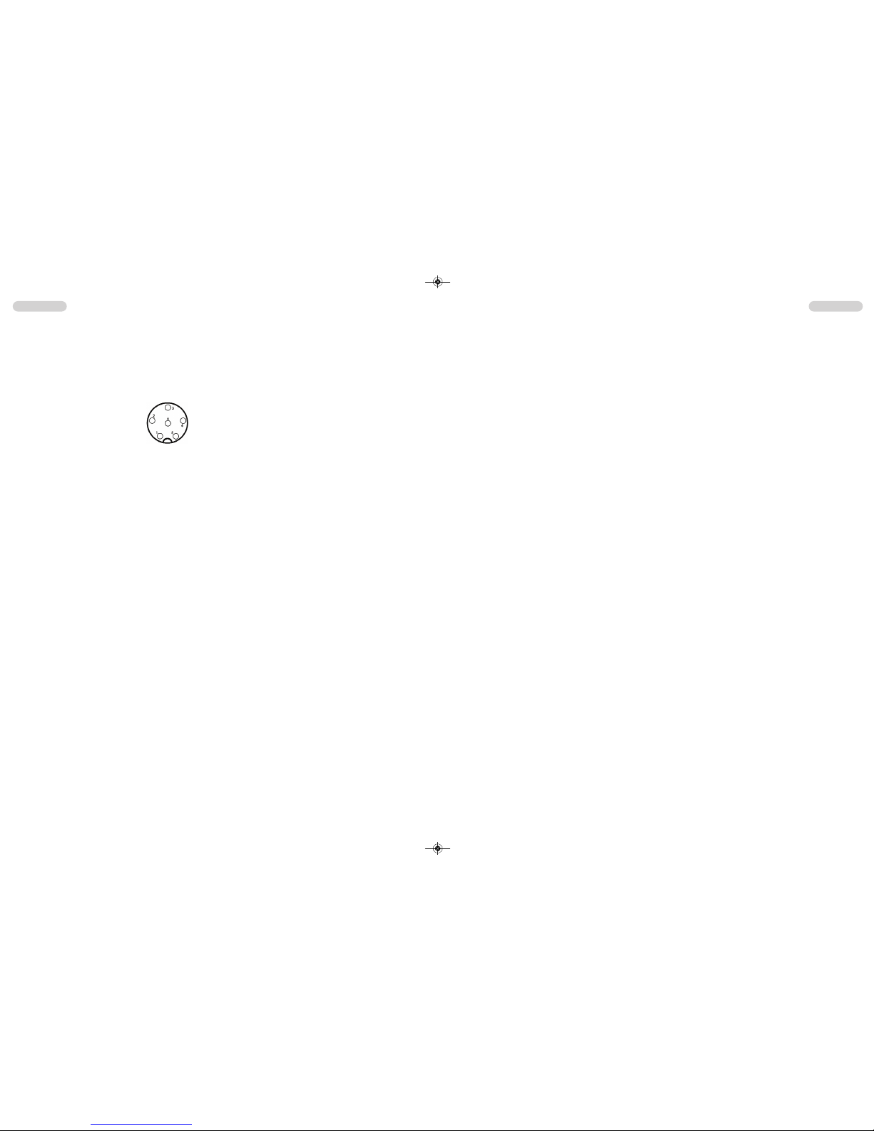
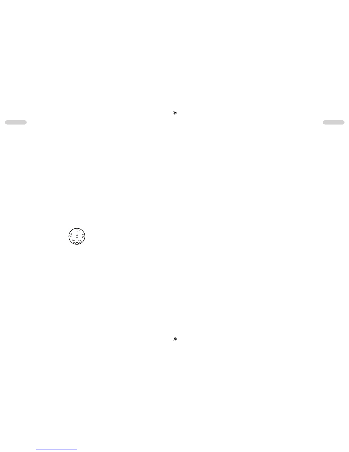
lich. Die Mikrofonbuchse ist nach GDCH-Standard angeschlossen:
PIN 1 Modulation PIN 2 Lautsprecher
PIN 3 PTT PIN 4 Up/Down
PIN 5 Masse PIN 6 +12 Volt
5) Stromversorgung
Vor dem Anschluss der Stromversorgung schalten Sie das Gerät aus, indem Sie den Laut-
stärkeregler ( 10 ) [ Off / Vol ] bis zum Einrasten nach links drehen.
Verbinden Sie die beiden blanken Anschlüsse am Ende des Kabels mit dem 12 V Bord-
netz Ihres Fahrzeuges. Das Stromversorgungskabel sollte möglichst weit von störenden
Aggregaten verlegt werden. Achten Sie beim Anschluss auf die richtige Polarität:
SCHWARZ wird mit "-" ( = MINUS / Masse ) des KFZ verbunden.
ROT wird mit "12 Volt +" ( = PLUS ) des KFZ/LKW-Bordnetzes verbunden.
Bei Verwendung von Dauerplus bleiben die letzten Einstellungen auch nach dem Ausschal-
ten des Gerätes und dem Abstellen des Motors gespeichert.
Nachdem die Antenne, das Mikrofon und die Stromversorgung sorgfältig angeschlossen sind,
kann der Funkbetrieb aufgenommen werden.
Deutsch Deutsch
6 7
Ansicht von der Lötseite der
Mikrofonbuchse bzw. Vorderan-
sicht des Mikrofonsteckers
ts-9m_manual_2:RoadCOM manual.qxd 05.09.2011 13:11 Seite 6

8) Kanalsuchlauf [ SC ]
Bei aktiver Kanalsuchlauffunktion werden alle Kanäle der eingestellten Norm nacheinander
durchsucht bis ein besetzer Kanal gefunden wird. Die Suchlauffunktion wird unterbrochen bis
das Signal endet, um dann fortzufahren.
Die Kanalsuchlauffunktion wird durch Drücken der SC-Taste (10) aktiviert bzw. deaktiviert. Im
aktiven Zustand erscheint in der Anzeige das SC Symbol (3B).
9) Anzeige AM-Sendeleistung H/L
In den meisten Normen wird auf den AM Frequenzen mit einer Sendeleistung von 1 Watt
gesendet. In diesen Fällen ist in der Anzeige (3B) der Buchstabe L (low - niedrig) zu sehen.
10) Anschlussbuchse für einen externen Zusatzlautsprecher
Das TS-9M hat an der Geräterückseite eine Klinkenbuchse (15) (3,5 mm ø) zum Anschluss
für einen externen Lautsprecher mit 4 - 8 Ohm Impedanz (z.B. TEAM TS-500). Bei Anschluss
des externen Lautsprechers wird der interne Lautsprecher abgeschaltet.
Bei 4 Ohm sollte die Belastbarkeit des Lautsprechers 4 Watt betragen.
DeutschDeutsch
8 9
Hinweis für die Norm UK:
In der Norm UK wird nur die Betriebsart FM angezeigt. Durch Drücken des AM/FM-Schalters
(7) wird zwischen den FM-Frequenzbändern EC oder UK umgeschaltet. Die Norm UK ver-
fügt über 40 Kanäle FM UK (27,60125 - 27,99125 MHz) und 40 Kanäle FM EC (26,965 -
27,405 MHz).
5) Umschaltung der Normen
Die Geräteversion "TS-9M Multi Norm" kann vom Benutzer auf eine der folgenden Normen
eingestellt werden:
Norm Kanäle und Frequenzen Anzeige
DE 80 FM (26,565 - 27,405 MHz), 4 W / 40 AM (26,965 - 27,405 MHz), 1 W DE
UK 40 FM (27,60125 - 27,99125 MHz), 4 W / 40 FM (26,965 - 27,405 MHz), 4 W UK
EI 40 FM (26,965 - 27,405 MHz), 4 W / 40 AM (26,965 - 27,405 MHz), 4 W EI
EU 40 FM (26,965 - 27,405 MHz), 4 W / 40 AM (26,965 - 27,405 MHz), 1 W EU
EC 40 FM (26,965 - 27,405 MHz), 4 W EC
PL 40 FM (26,960 - 27,400 MHz), 4 W / 40 AM (26,960 - 27,400 MHz), 4 W PL
Zum Einstellen bzw. Umschalten der Normen halten Sie bitte den Modulationarten-Umschal-
ter ( 4 ) [ AM/FM ] während dem Einschalten des Gerätes gedrückt. In der Anzeige erscheint
das Kürzel der aktuellen Norm. Alle anderen Symbole sind nicht sichtbar. Die gewünschte
Norm wird mit Hilfe der Kanalwahltasten (4) / (5) eingestellt.
Zum Bestätigen der Norm das Gerät kurz aus- und wieder einschalten.
Für die Erlaubnis und die Auflagen zum Betrieb der verschiedenen Normen in den ein-
zelnen Ländern sehen Sie in den Gerätepass. Der Benutzer ist für die richtige Einstel-
lung der gültigen Norm im jeweiligen Land eigenverantwortlich.
Hinweis:
Die Ausführung TS-9M c (EC CEPT) ist fest auf 40 Kanäle FM / 4 Watt eingestellt und
somit für den Betrieb in Österreich geeignet.
6) Senden
Zum Senden wird die im Mikrofon (1) eingebaute Sendetaste (2) gedrückt und für die Dauer der
Durchsage gehalten. In dieser Zeit leuchtet das Sendekontroll-Symbol (3C) in der Anzeige.
Sprechen Sie in das Mikrofon aus ca. 5 cm Entfernung mit normaler Lautstärke. Zu lautes
oder zu leises Besprechen vermindert die Signalqualität. Nach Beendigung der Durchsage
die Sprechtaste (2) loslassen. Das Gerät schaltet automatisch in den Empfangsbetrieb
zurück.
7) Vorrangkanal 9 / 19 [ CH9/19 ]
Das Gerät verfügt über die Vorrangkanäle 9 und 19. Durch einmaliges Drücken der Vorrang-
kanaltaste ( 11 ) [ CH9/19 ] wird Kanal 9 eingestellt. Zum Einstellen von Kanal 19, die Vor-
rangkanaltaste zwei Mal Drücken.
ts-9m_manual_2:RoadCOM manual.qxd 05.09.2011 13:11 Seite 8

Deutsch Deutsch
11
HINWEISE
1) Sicherheitshinweis
Bitte beachten Sie als KFZ-Fahrer beim Funkbetrieb auch die Bestimmungen der jeweils gülti-
gen Straßenverkehrsordnung. Bei dem Betrieb des Gerätes wird Hochfrequenzenergie freige-
setzt. Es muss daher ein entsprechender Sicherheitsabstand zur Antenne eingehalten werden.
2) Allgemeine Hinweise
Das Gerät ist vor Feuchtigkeit und Staub zu schützen. Das Gerät niemals an Orten aufbe-
wahren, die einer starken Erhitzung und/oder direkter Sonneneinstrahlung ausgesetzt sein
könnten. Zur Gehäusereinigung ein weiches, fusselfreies Tuch verwenden. Zur Reinigung
niemals Lösungsmittel verwenden.
3) Service
Das Gerät darf nicht geöffnet werden. Eigenhändige Reparaturen oder Abgleich sind nicht
vorzunehmen, denn jede Veränderung, bzw. Fremdabgleich, können zum Erlöschen der
Betriebserlaubnis sowie der Gewährleistungs- und Reparaturansprüche führen. Bei Betriebs-
störungen sollte das Gerät nicht benutzt werden. Trennen Sie in diesem Fall die Stromver-
sorgung ab. Liegt ein Defekt vor, sollte auf jeden Fall der autorisierte TEAM-Fachhändler kon-
taktiert werden.
4) Konformität
TEAM TS-9M
Das CB-Mobilsprechfunkgerät TEAM TS-9M entspricht der europäischen R&TTE Direktive
und hält die europäischen Normen EN 300 135-1/-2, EN 300 433-2, EN 301 489-1/-13 und
EN 60950-1 ein. Die genauen Länderbestimmungen der verschiedenen Versionen entneh-
men Sie bitte dem beiliegenden Gerätepass.
5) Entsorgung
Bitte werfen Sie Ihr TEAM-Altgerät nicht einfach auf den Müll, sondern senden Sie Ihr Altge-
rät bitte portofrei zur fachgerechten Entsorgung an TEAM ein. TEAM wird anschließend die
umweltschonende Entsorgung Ihres Altgerätes für Sie kostenlos veranlassen. Bitte machen
Sie mit - der Umwelt zuliebe.
- Änderung der technischen Daten und der Ausführung sind ohne Vorankündigung vorbehalten. -
10
ts-9m_manual_2:RoadCOM manual.qxd 05.09.2011 13:11 Seite 10

English English
Setting up the TEAM TS-9M
1) Installation of a CB antenna
The antenna is one of the most critical parts in the setup. The type of antenna and its loca-
tion has a great effect on the range of operation. Please consider the following criteria for
selection of the best location and installation of your antenna:
> Make sure that the antenna is designed for radio operation on 27 MHz.
> The location of the antenna should be as high as possible without any obstacles nearby.
> The aerial cable should not be damaged and the plugs should be properly connected.
> Make sure that the antenna cable is not bent.
When you install a mobile antenna please note the following advices:
> The antenna should be fixed in the center of a big body-part, e.g. the trunk.
> The mobile antenna coil should have the closest possible contact with a conducting metallic
surface of the bodywork of the car.
There are also some other possibilities to fix the antenna onto the car without the necessity
to drill a hole into the bodywork of your car, e.g. mounting the antenna onto the gutter, mount-
ing the antenna onto a holder on the cover of the boot or using an antenna with a magnetic
foot or using a windscreen antenna.
2) Aerial Connection
Before pressing the transmit key, a suitable aerial must be connected. The PL259 plug of the
aerial cable ( coax ) is connected to the SO239 socket ( 13 ) on the rear panel. Make sure,
that all plugs are firmly tightened and properly soldered. Insufficient connections can damage
the radio and will reduce the range of operation.
The antenna should be matched with the radio, otherwise a part of the transmit power will be
reflected at the antenna and will not be radiated. This reduces the range of operation. The
matching of antenna to radio, is performed by a length adjustment of the antenna radial in
aim for a minimal SWR ratio which can be measured by a SWR meter,e.g. TEAM SWR
1180P. After the measurement the SWR meter should be removed from the antenna line.
3) Installation in the car
When you want to fix the unit in your car, you can either fasten it with the help of the included
mounting bracket below the dashboard. Always mount the transceiver where the switches are
easily accessible. Other important points to consider for a correct mounting position are:
> no interference of the roadworthiness,
> good access to the controls of the car,
> sufficient air circulation to prevent overheating of the radio in transmit mode.
Please consider the angle of view onto the display while driving. From a certain angle of view,
the readability of the display diminishes. An intensive solar irradiation can also affect the rea-
dability of the display. So it is recommended to check the best position before the final instal-
lation. The unit can easily be fixed onto different positions in the car by using the enclosed
mounting bracket.
TABLE OF CONTENTS
Setting up the TEAM TS-9M
1) Installation of a CB antenna 13
2) Aerial Connection 13
3) Installation in the car 13
4) Microphone 14
5) Power source 14
Operation of the TEAM TS-9M
1) Switching on [ Off / Vol ] 15
2) Squelch [ SQ / ASQ ] 15
3) Channel selection [ q] [ p]15
4) Modulation selection [ AM/FM ]15
5) Norm selection 16
6) Transmitting 16
7) Priotitiy Channels 9 / 19 16
8) Channel Scan 16
9) AM Transmission Power 17
10) External speaker jack 17
Additional Information
1) Safety Instructions 17
2) General Precautions 17
3) Servicing 17
4) Conformity 17
Channel Frequencies 18
Specifications 19
Schematic Diagram & PCB layout 20 - 23
12 13
ts-9m_manual_2:RoadCOM manual.qxd 05.09.2011 13:11 Seite 12
4) Microphone
Plug the microphone ( 1 ) into the 6 pin socket ( 12 ) on the front panel. Note it will only go in
one way round. No transmission and receiving is possible without the microphone. The pin
assignment of the GDCH standard microphone plug is given below:
PIN 1 Modulation
PIN 2 Loudspeaker
PIN 3 PTT
PIN 4 Up/Down
PIN 5 Ground
PIN 6 +12 Volt
Solder side view of the microphone connector or top view of the microphone plug.
5) Power source
Before connecting the unit to a suitable power source via the fused DC power cable (15), the
device must be switched off by turning the volume control ( 9 ) [ Off / Vol ] counterclockwise
to the very end until a clicking sound is heard.
Then, connect the two naked leads at the end of the cable with the supply voltage of the
car/lorry battery. The unit is designed to operate with 12 volts and a negative ground electri-
cal system. Lay the cable as far as possible away from aggregates which can cause interfe-
rence. Watch for the correct polarity during the connection.
BLACK connect to - MINUS / ground of the car battery.
RED connect to 12 volts + PLUS of the car/lorry battery.
If the power source is not disconnected after putting the engine off, the last settings will
remain stored, after the unit and the car are switched off.
After proper connection of the microphone, the aerial and power source, radio operation can
be started.
Operation of the TEAM TS-9M
1) Switching on [ Off / Vol ]
To turn on the radio, turn the On / Off switch (10) [ Off / Vol ] clockwise.
With the help of the squelch control (8) you can set a comfortable volume level. Set the manu-
al squelch (SQ) to a level where the constant noise of an empty channel is audible - see para-
graph 2) Squelch. Now, adjust the volume level.
The memory function stores the last settings, i.e. norm, frequency band and channel after turn-
ing the radio off and on again.
2) Squelch [ SQ / ASQ ]
The strong background noise, which occurs always on free channels, can be suppressed by
the squelch function, which has an automatic and a manual mode.
By turning the squelch control (8) slowly clockwise you will find a point where the noise dis-
appears. The squelch control should only be turned up far enough to stop the background
noise on an unused channel. Turning the control further clock-wise will increasingly suppress
stronger interfering signals as well as weak stations.
The automatic squelch [ ASQ ] (7) uses a preset average value. This function is turned on/off
by pressing the ASQ key (7). The automatic squelch mode is indicated by the AQ symbol (6F)
in the LCD.
3) Channel selection [ q] [ p]
All channels can be selected by pushing the channel selector keys (5) [ qCH ] and (6) [ pCH ]
located on the front panel of the radio. The selected channel is displayed on the LCD (3). No
channel selection is possible while the radio is in transmission mode. The channels are
arranged in a consecutive order, in a ring-like-system, i.e. after the highest channel number it
starts again with channel no. 1 and vice versa. For communication with a partner CB station,
both transceivers must be adjusted to the same channel and the same modulation type.
4) Modulation selection [ AM/FM ]
For the TS-9M, the operating modes AM and FM are available. However, the version TS-9M c
(EC CEPT) and the norm EC of the the version TS-9M Full Multi Norm operate in FM only.
The selected modulation type is indicated by the AM/FM symbol (3E). To toggle between the
modes press the mode key (4) [ AM/FM ].
If the selected norm does not accept the modulation type AM on the actual channel, it will
remain on the modulation type FM.
If the radio is set to AM on the actual channel, and you select another channel, on which the
AM mode is inhibited, the modulation changes automatically to FM mode. If you select once
more another channel, on which the AM mode is allowed again, the modulation switches auto-
matically to back to AM mode.
With norm UK in the version TS-9M Full Multi Norm, you toggle between the EC band and
the UK band, which are indicated by the symbols EC and UK, by pressing the mode key (7)
[ AM/FM ]. The CB band EU consists of the 40 CEPT channels. The CB band UK consists of
40 channels starting from 27.60125 MHz to 27.99125 MHz.
After turning the radio off, the TS-9M stores the last channel and the frequency band.
English English
14 15
ts-9m_manual_2:RoadCOM manual.qxd 05.09.2011 13:11 Seite 14

5) Norm Selection
The version TS-9M Full Multi Norm can be set by the user to the following norms:
DE 80 FM
(26.565 - 27.405 MHz), 4 W / 40 AM (26.965 - 27.405 MHz), 1 W
EU 40 FM (26.965 - 27.405 MHz), 4 W / 40 AM (26.965 - 27.405 MHz), 1 W
EC 40 FM (26.965 - 27.405 MHz), 4 W
UK 40 FM (27.60125 - 27.99125 MHz), 4 W / 40 FM (26.965 - 27.405 MHz), 4 W
PL 40 FM (26.960 - 27.400 MHz), 4 W / 40 AM (26.960 - 27.400 MHz), 4 W
EI 40 FM (26.965 - 27.405 MHz), 4 W / 40 AM (26.965 - 27.405 MHz), 4 W
For changing the current norm, please hold the mode key ( 4 ) [ AM/FM ] while turning the
radio on. In the display, the symbol of the current norm appears, while all other symbols
disappear. Select the norm with the channel selector keys (5) and (6) and confirm your selec-
tion by turning the radio off and on again.
Regarding the permissions and restrictions of the individual norms in the various european
countries, please check the radio passport, which is included in the scope of delivery. The
user is solely responsible for the selection of the permissible norm in country of operation.
Note:
The norm TS-9M c(EC CEPT) is fixed to 40 channels FM / 4 Watts only.
6) Transmitting
To transmit, press and hold the transmission key ( 2 ) at the microphone ( 1 ). The TX symbol
will appear in the LCD (3C).
For best quality, speak normally at a distance of 2 - 4 inches. Speaking too loudly will cause dis-
tortions and make the signal difficult to understand.
While the set is in the transmit mode there is no key entry possible and the receiver is muted.
On completion of the transmission release the PTT key ( 2 ) and the radio will revert to receiv-
ing mode.
7) Priority Channel 9 / 19 [ CH9/19 ]
The TS-9M contains the priority channels 9 and 19. Priority channel 9 is selected by pressing
the key ( 11 ) [ CH9/19 ] once. To set priority channel 19, press the key ( 11 ) [ CH9/19 ] twice.
8) Channel Scan [ SC ]
The channel scan function searches all frequencies of the selected norm in consecutive order until
a signal is detected. The scan function pauses until the signal ceases. Then, the scan functions
continues.
Activate or deactive the scan function by pressing the SC-key (10). In the activated state the SC-
symbol ( 3A ) is displayed.
EnglishEnglish
9) AM Transmission Power H/L
In most of the country norms, the transmission power on AM frequencies is 1 Watt. In these cases,
the letter L (for low tx power) is displayed ( 3B ).
10) External speaker jack
The TS-9M is equipped with a 3.5 mm jack socket ( 16 ) at the rear panel to connect an exter-
nal speaker of 4 - 8 ohm impedance, e.g. TEAM TS-500. At 4 ohms the speaker load can be
4 watts. When the external speaker is connected, the internal speaker will be switched off.
Additional information
1) Safety instruction
Drivers must obey traffic rules regarding the use of transceivers in a vehicle.
The unit radiates RF energy in transmit mode. Please keep an eye on safety distance to the
antenna.
2) General precautions
Protect the mobile radio from humidity and dust. Do not store at places where the tempera-
ture may rise and cause damage, for example in the sun. The set can be cleaned by wiping
with a soft cloth. Do not use chemical products to clean the unit.
3) Servicing
The device must not be opened. Independent repairs or adjustment must not be carried out,
since each modification or unauthorized intervention will result in withdrawal of the operation
permit and of warranty and repair claims. Do not use the mobile radio if it seems not to func-
tion correctly. Disconnect the radio from the DC power source immediately. If there is a
defect, the authorized TEAM specialist dealer or TEAM must be contacted immediately.
4) Conformity
The CB mobile transceiver TEAM TS-9M complies to the European directive R&TTE and
meets the European standards EN 300 135-1/-2, EN 300 433-2, EN 301 489-1/-13 and EN
60950-1. The Declaration of Conformity is included in this manual.
The specific regulations of the different versions in the different european countries can be found
in the radio passport that is included in this manual.
Specifications are subject to change without any prior notice or obligation on the part of the manufacturer.
16 17
ts-9m_manual_2:RoadCOM manual.qxd 05.09.2011 13:11 Seite 16

English English
18 19
Technische Daten / Technical data / Caractéristiques /
Características técnicas / Technische gegevens
Empfängerempfindlichkeit / Receiver Sensitivity / FM : 0.8µV / 1.2 KHz;
Sensibilité du récepteur / Sensibilidad Receptor / 20 dB ( S+N+D)/N
Ontvangergevoeligheid AM : 1.45µV / 60%;
20 dB ( S+N+D)/N
Zwischenfrequenzen / Intermediate frequencies / 1. ZF/IF 10.695 MHz
Fréquences Intermedie / Frecuencia intermedia / 2. ZF/IF 455 KHz
Middenfrequenties
Squelch Empfindlichkeit / Squelch Sensitivity / 1.0 µV - 2.0 mV
Sensibilité du Squelch / Sensibilidad Squelch /
Squelch gevoeligheid
NF-Ausgangsleistung /Audio Output Power / 1.9 W / 8 Ohm
Puissance de sortie audio / Potencia Salida Audio / ( 10% THD )
LF-uitgangsvermogen
Sendeleistung / TX output power / Puissance d’emission / FM max. 4 W / 50 Ohm
Potencia de Salida / Zendvermogen AM max. 4 W / 50 Ohm
Hub / Deviation / Déviation / Desviasión / max. 2 KHz / FM
Balayage de fréquence / Frequentieverschuiving
Modulationsgrad / Modulation Degree 85 % max. AM
Degré de modulation / Grado de modulación /
Modulatiegraad
Frequenztoleranz / Frequency tolerance / max. 600 Hz
Tolérance de fréquence / tolerancia de frecuencia /
Frequentietolerantie
Ober-/Nebenwellenunterdrückung / 4 x 10 W
Harmonic / spurious suppression / 2.5 x 10 W
Réjection des (non) harmoniques /
Supresión de los armónicos /
Onderdrukking van storingen
Stromaufnahme / Current consumption / FM: 1100 mA / TX
Consommation / Intensidad absorbida / AM: 1W - 600 mA / TX
Stroomverbruik 4W - 1800 mA / TX
Betriebsspannung / Power Supply Voltage / max. 12 V nom.
Alimentation / Alimentación / Voedingsspanning
Abmessungen / dimensions / dimensions / 123 mm x 43 mm x 162 mm
Dimensión / Afmetingen
Gewicht / weight / Poids / Peso / Gewicht 795 gr.
<
_
+
_
-9
<
_-9
TEAM TS-9M
Kanal - Frequenz ( MHz ) / Channel - Frequency ( MHz ) / Canaux - Fréquence ( MHz ) /
Canal - Frecuencia ( MHz ) / Kanaal - Frequentie ( MHz )
01 - 26.965
02 - 26.975
03 - 26.985
04 - 27.005
05 - 27.015
06 - 27.025
07 - 27.035
08 - 27.055
09 - 27.065
10 - 27.075
11 - 27.085
12 - 27.105
13 - 27.115
14 - 27.125
15 - 27.135
16 - 27.155
17 - 27.165
18 - 27.175
19 - 27.185
20 - 27.205
21 - 27.215
22 - 27.225
23 - 26.255
24 - 27.235
25 - 27.245
26 - 27.265
27 - 27.275
28 - 27.285
29 - 27.295
30 - 27.305
31 - 27.315
32 - 27.325
33 - 27.335
34 - 27.345
35 - 27.355
36 - 27.365
37 - 27.375
38 - 27.385
39 - 27.395
40 - 27.405
41 - 26.565
42 - 26.575
43 - 26.585
44 - 26.595
45 - 26.605
46 - 26.615
47 - 26.625
48 - 26.635
49 - 26.645
50 - 26.655
51 - 26.665
52 - 26.675
53 - 26.685
54 - 26.695
55 - 26.705
56 - 26.715
57 - 26.725
58 - 26.735
59 - 26.745
60 - 26.755
61 - 26.765
62 - 26.775
63 - 26.785
64 - 26.795
65 - 26.805
66 - 26.815
67 - 26.825
68 - 26.835
69 - 26.845
70 - 26.855
71 - 26.865
72 - 26.875
73 - 26.885
74 - 26.895
75 - 26.905
76 - 26.915
77 - 26.925
78 - 26.935
79 - 26.945
80 - 26.955
01 - 27.60125
02 - 27.61125
03 - 27.62125
04 - 27.63125
05 - 27.64125
06 - 27.65125
07 - 27.66125
08 - 27.67125
09 - 27.68125
10 - 27.69125
11 - 27.70125
12 - 27.71125
13 - 27.72125
14 - 27.73125
15 - 27.74125
16 - 27.75125
17 - 27.76125
18 - 27.77125
19 - 27.78125
20 - 27.79125
21 - 27.80125
22 - 27.81125
23 - 26.82125
24 - 27.83125
25 - 27.84125
26 - 27.85125
27 - 27.86125
28 - 27.87125
29 - 27.88125
30 - 27.89125
31 - 27.90125
32 - 27.91125
33 - 27.92125
34 - 27.93125
35 - 27.94125
36 - 27.95125
37 - 27.96125
38 - 27.97125
39 - 27.98125
40 - 27.99125
DE UK
CEPT / EC /
EU / EI / DE
01 - 26.960
02 - 26.970
03 - 26.980
04 - 27.000
05 - 27.010
06 - 27.020
07 - 27.030
08 - 27.050
09 - 27.060
10 - 27.070
11 - 27.080
12 - 27.100
13 - 27.110
14 - 27.120
15 - 27.130
16 - 27.150
17 - 27.160
18 - 27.170
19 - 27.180
20 - 27.200
21 - 27.210
22 - 27.220
23 - 26.250
24 - 27.230
25 - 27.240
26 - 27.260
27 - 27.270
28 - 27.280
29 - 27.290
30 - 27.300
31 - 27.310
32 - 27.320
33 - 27.330
34 - 27.340
35 - 27.350
36 - 27.360
37 - 27.370
38 - 27.380
39 - 27.390
40 - 27.400
PL
ts-9m_manual_2:RoadCOM manual.qxd 05.09.2011 13:11 Seite 18

20 21
Q28
2SC5065(MAY)
R75
270R
C136
151P(J)
C137
151P(J)
C138
47P(J)
R42
220R
C139
16P(F)
D22
JDV2S14E(FH)
D21
HVU307(7)
L5
240nH-XL
L6
270nH-XL
R121
22
K
C21
103P
C140
5P(B)
R23
10
K
D23
JDV2S14E(FH)
C99
10P(F)
C68
103P
R144
1K8
E16
3.3uF/16V
R199
1
K
R197
10
K
R195
1
K
C126
102P
TP1
PD
R164
390R
R181
47
K
C20
103P
E22
ANT
L17
0.8*6.3*7.5TR
L19
0.8*6.3*7.5TR
L18
0.8*6.3*7.5TR
R33
10
K
C164
68P(J)
C152
181P(J)
C121
22P(F)
C162
151P(J)
C163
39P(J)
C161
151P(J)
L16
0.8*6.3*7.5TR
C159
68P(J)
C151
271P(J)
Q38
2SC2078
Q37
2SC2314(F)
L12
DK3*5*1
R211
33R
R114
3R3
C158
391P(J)
C157
56P(J)
L11
DK3*5*1
R210
22R
R209
22R
C156
121P(J)
C155
27P(F)
C123
N
C
D18
N
C
R83
N
C
C73
473P
Q36
2SC941TM(O)
L10
330nH-XL
R72
56R
C71
103P
L4
MPZ2012S101A
R125
3K3
R85
1K8
C49
102P
Q7
2SC2714(QY)
R68
220R
R71
56R
R122
27
K
C153
24P(F)
C150
221P(J)
R67
220R
C95
473P
C50
103P
L7
VCC-L(0.55)
C42
103P
C41
103P
C40
103P
13V
Q33
*2SB1135R
R208
*82R
R183
*47
K
Q32
*2SC3052(LF)
R206
*100R
R61
*5K6
C91
*473P
R171
*1K5
R95
*1
K
8V
W3
*2K2
R207
*82R
PA/RSSI
R161
N
C
REF
R28
220
K
R29
220
K
R30
220
K
C148
331P C132
101P
C92
33P
R31
220
K
R32
220
K
C149
82P
C93
101P
R56
2K2
R57
2K2
R124
3K3
C94
473P
R98
1
K
R177
39
K
R172
2K2
E7
47uF/16V
AMC
W5
4K7
AMC
MOD AF
VCO-RF
C48
103P
RX IN
41
3
25
T7
TF-215-8X11
C90
473P
REF
JK1
EX SP
R192
4R7(2W)
C127
471P
1
2
J1
SP
SP-
C1
22P(F)
D1
1SS356
C2
472P
D2
1SS356
31
2
54
T1
1131 C8
102P
R44
2K2
C51
47P(J)
R34
10
K
R58
560R
E3
47uF/16V
31
2
45
T3
1227
3 1
2
5 4
T2
1153
C76
1P5(B)
R59
8K2
G
DS
Q8
2SK210(YG)
G
DS
Q9
2SK210(YG)
R74
270R
R73
270R
C53
103P C55
103P
3 1
2
4
5
6
T4
1120
R35
N
C
C13
103P
R76
1
K
CB1
10.695MHZ
R77
560R
R78
100
K
IN
1OUT 5
2
2
3
3
4
4
CF1
CF455H
R99
1K8
Q10
2SC3052(LF)
R47
2K2
R115
47
K
R116
10R
R117
150R
C98
473P
3 1
2
4 5
T6
1179
R118
47R
C83
473P
R5
10
K
R126
1M
C131
222P
R142
68
K
R136
68
K
R134
56
K
R131
68
K
R130
680
K
C17
272P
R4
8K2
C23
103P
R3
100
K
C116
105P
R179
47
K
R140
100
K
R141
100
K
R1
10
K
C18
102P
E1
4.7uF/25V R45
1
K
E8
1uF/25V
C54
103P
C52
103P
R62
560R
R106
N
C
R137
N
C
C104
N
C
R88
1
K
C62
103P
R63
390R
R69
22R
C11
102P
PA/RSSI
MIX LO
R163
27
K
R107
47
K
R48
2K2 R167
1M5
R60
8K2
R138
100
K
R168
1K5
W2
2K2
R108
4K7
R173
560
K
SQV
R
SQ
R151
150
K
R127
1M
E5
47uF/16V
R14
10
K
R109
4K7
C102
103P
R70
56R
R153
470
K
R105
4K7
R154
12
K
C103
104P
VOL W
R156
15
K
C65
153P
R157
5K6
MOD AF
+V
C37
103P
E18
470uF/25V
C36
103P
8V
TX EN
8T
R37
100R
C9
103P
R38
100R
C10
103P C12
103P
C14
102P
C84
473P
C82
225P
C57
103P
AF MUTE
8T
C125
103P
Y3
10.24MHZ
C146
104P
C145
68P(J)
R185
22R
5C
R204
2K2
R203
2K2
R202
2K2
C144
101P
C143
101P
C142
101P
C124
103P
2st
VCO- RF
R80
560R
C19
102P
R102
15
K
R135
56
K
R65
220R
MIX LO
C63
103P
R66
220R
C122
5P(B)
R178
47
K
R184
470R
R89
470R
C22
471P
C33
103P
PLL-LE
PLL-CL
K
PLL-DATA
C106
473P
R7
150
K
R51
2K2
C69
103P
C105
104P W7
4K7
R158
2K2
R169
1K5
MOD AF
S
Q
AMP
1ST AMP
RX IN
Q17
DTC114EE
Q31
DTC114EU
D17
KDS160E(UF)
D15
*1N4148
D10
N
C
D3
KDS16 0E( UF)
D8
KDS16 0E( UF)
D4
KDS160E(UF)
D6
KDS160E(UF)
D12
KDS160E(UF)
D7
KDS160E(UF)
Q6
2SC2714(QY)
Q4
2SC2714(QY)
Q5
2SC2714(QY)
Q1
2SC2714(QY) Q11
2SC3052(LF)
Q12
2SC3052(LF)
Q35
2SA1235(MF)
8V
3
2
1
84
U1A
N
JM12904
5
6
7
U1B
N
JM12904
8V
8V
8V5C
Q26
2SD1048(X6)
R182
100
K
R21
3K3
C32
103P
VCO EN
5C
C31
103P
8T
Q25
2SD1048(X6)
C72
N
C
R180
15
K
C75
473P
C27
471P
8V
SQ
C67
103P
8V
C166
*103P
L13
0.6*4*6.5TL
R94
10
K
8V
Q39
DTC114EE
Q29
2SC3052(LF)
TP9
DET AF
TP2
AMP BPF
TP13
10.24MHZ
C175
105P
R218
10
K
R219
3K3
E15
224P
D27
1SV283(TE)
C181
102P
R226
100
K
C182
47P(J)
C184
101P(J)
D29
1SV283(TE)
D28
1SV283(TE)
R227
100
K
R228
100
K
C180
103P
C179
103P
RX-BFO
RX-BFO
D20
SB340
R52
1K8
R159
5K6
C107
223P R160
5K6
C108
104P
R25
10
K
8V
R110
4K7
C70
103P
E21
220uF/16V
R148
47
K
R147
33
K
C47
102P R26
10
K
C118
104P
R27
10
K
R53
2K2
R96
1
K
C119
105P
R188
270
K
R150
47
K
R149
47
K
C109
104P
R55
2K2
R54
2K2
Q34
2SA1235(MF)
R176
39
K
D25
3V
R82
750R
8V
R97
1
K
MIC
Q23
DTC114EE
D16
KDS160E(UF)
Q27
2SD1048(X6)
Q16
2SC3052(LF)
E19
470uF/25V
R112
150R
8V
TP11
MIC
E27
1000uF/25V
5C
Q21
2SC3052(LF)
R187
4K7
PTT
C189
103P
VOL H
8T
8T
R20
18
K
D9
KDS160E(UF)
R6
10
K
C88
473P
R145
33
K
C58
473P
C30
101P
C16
102P
G
1
D2
S3
Q43
2SK1824
C110
102P
R41
1
K
R91
15
K
C44
15P(F)
2s
t
G1
D
2
S
3
Q14
2SK1824 R19
2K2
8V
C114
221P(J)
R129
4K7
C117
472P
R132
47
K
ASQ
W6
*2K2
C78
*103P
H/L
Q15
*DTC114EE
FM/AM EN
FM/AM EN
FM/AM EN
C130
68P(J)
R24
10
K
C133
68P(J)
FRQ
D24
1N4002
C147
331P(J)
QX310-RF-V2
3
2
1
411
U3A
N
JM2902
5
6
7
U3B
N
JM2902 10
9
8
U3C
N
JM2902
12
13
14
U3D
N
JM2902
C15
224P
C39
225P
Vin 3
Vss
1
Vout
2
U7
78L05BP
C26
103P
1
2
3
4
J2
CON4
+V
13V
SP-
Vin 1
Vss
2
Vout
3
U11
L78M08CDT
VCO EN
PLL-LE
PLL-CL
K
PLL-DATA
SQVR
SQ
ASQ
AF MUTE
VOL H
FM/AM EN
VOL W
FRQ
TX EN
PTT
H/
L
MIC
RX-BFO
16
15
1
2
3
4
5
6
7
8
13
9
12
14
10
11
U2
MC3361
C60
104P
C61
104P
R17
2
K
C64
102P
R15
470
K
C59
681P
C45
681P
E11
100uF/16V
R36
100R
C80
103P
R16
3K3
C35
104P
E2
4.7uF/16V
Y1
C24(455)
R18
5K1 C74
82P(J) C77
N
C
D11
5V1
R12
2K2
8V
C38
47P(F)
D5
1N4148
R13
150
K
C34
105P
1
2
3
4
5
6
7
8
9
10
11
12
13
14
15
16
17
18
19
20
J5
CON20
1
2
3
4
5
6
7
J4
CON7
R40
N
C
R11
N
C
R43
N
C
Q13
BV4
R49
10
K
R50
1
K
C81
475P
C85
225P
R79
100R
C87
225P
R84
100R
C86
225P
R86
330R
D26
1N4148
D14
1SV283(TE)
L15
0.8*6.3*7.5TR
Q2
DTC114EE 8T
L14
0.5*4*10.5T
R
C56
226P
R10
2K2
C79
225P
L1
TSK13.3*15*3.8
1
2
5
4
3
IC1
TDA2003V
C5
472P
C4
103P
E4
47uF/16V
R104
2R2
C6
224P
R92
33
K
R100
47R
E10
470uF/25V
E9
1000uF/25V C3
103P
+V
C7
5P(B)
FIN1
1
CP1
3
LE
8
DATA
7
CLOC
K
6
LD
5
Vcc 2
CP2 14
Vcc 15
SW 12
Fin2 16
BO 9
Gn
d
4
Gn
d
13
Xin 11
Xout 10
U10
MCD2926
D13
1SV283(TE)
R87
*1K5
G
1
D2
S3
Q3
*2SK1824
R9
*4K7
H/L
C25
15P(F)
C24
8P(B)
C28
15P(F)
C43
473P
RX-BFO
C29
15P(F)
W1
100
K
CB2
N
C
R39
0R
R22
0R
W4
4K7
R8
220R
Q20
DTC114EE
C46
224P
TP3
1ST
C89
475P
C66
103P
C96
103P
C111
103P
C101
103P
C97
103P
C100
103P
E6
100uF/16V
C113
391P C115
681P
R46
1
K
R64
1
K
C112
105P
L2
10uH
C120
102P
JMP
HPWR
PA/RSSI
8V
R2
100
K
R81
47
K
1
2
3
J3
CON3
L3
JMP
C128
104P
TP4
FRQ DC
TP5
AM MOD
C129
224P
Q18
*DTC114EE
HPW
R
C134
*103P L8
JMP
R90
*6K8
Q19
*DTC114EE
HPW
R
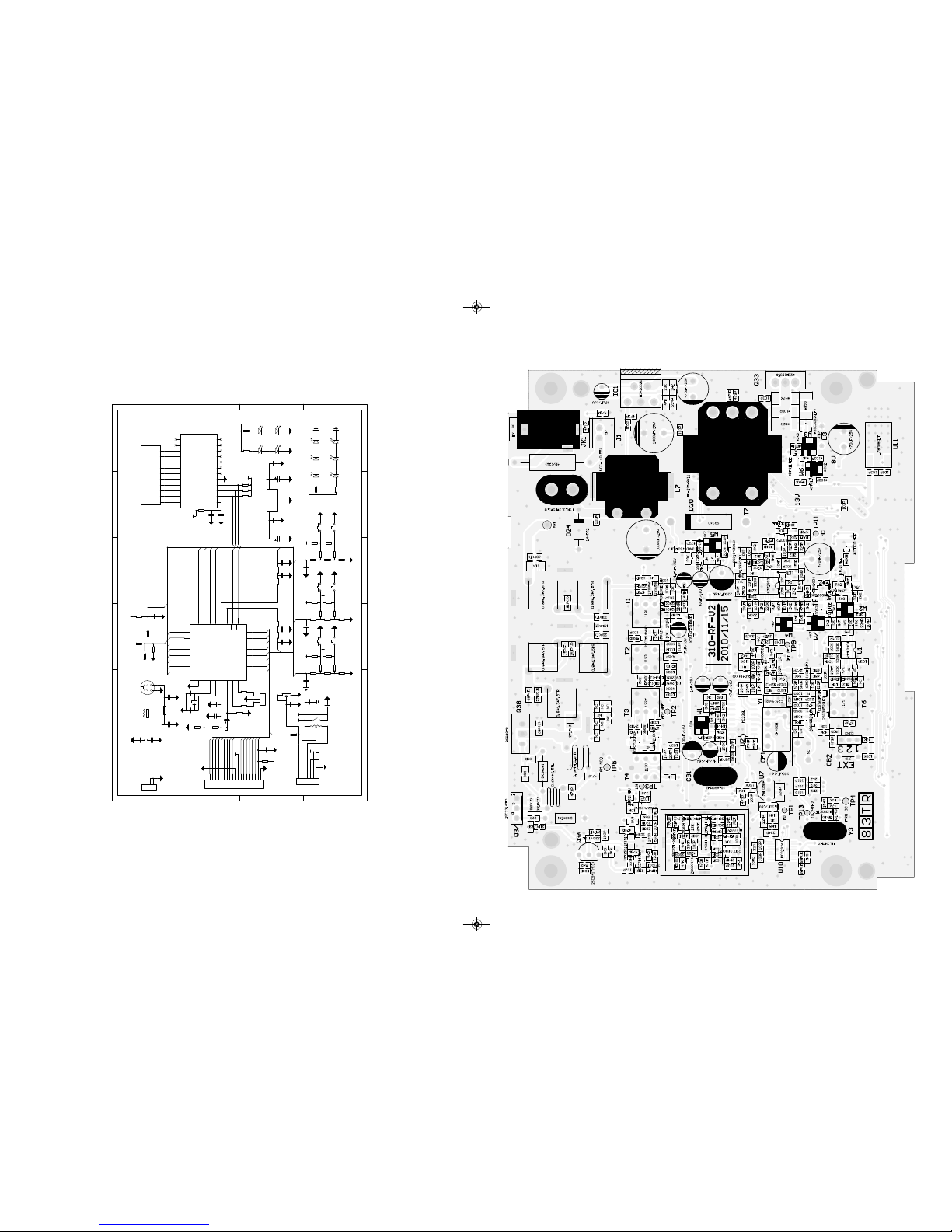
Schematic Diagram
TEAM Electronic GmbH
TS-9M
14.03.2011
ts-9m_manual_2:RoadCOM manual.qxd 05.09.2011 13:11 Seite 20
22
123456
A
B
C
D
6
54321
D
C
B
A
S800
SC
S801
UP
FRQ
8V 5V
E802
100uF/16V
Vin
3
Vss
1
Vout 2
U802
78L05
E801
100uF/16V
C805
103P C806
103P
C817
473P
R815
10
K
R814
10
K
C818
473P
R821
22R
C816
225P
C801
103P
5V
R820
10
K
R819
10
K
R818
10
K
5V
TS9M-LCD-V2
VDD
1
DIO
2
CL
K
3
STB
4
GND
5
SEG31
6
SEG30
7
SEG29
8
SEG28
9
SEG23
10
SEG22
11
SEG20
12 SEG15 13
SEG14 14
SEG13 15
SEG12 16
SEG7 17
SEG6 18
SEG5 19
SEG4 20
COM3 21
COM2 22
COM1 23
COM0 24
U801
TM1722
COM0
1
COM1
2
COM2
3
COM3
4
SEG0
5
SEG1
6
SEG2
7
SEG3
8
SEG4
9
SEG5
10
DS800
GD6407WP B-01
R804
1
K
D801
WTE
D803
WTE
D805
WTE
+V
R808
1K8
D800
WTE
D802
WTE
D804
WTE
R807
1K8
C820
473P
R816
10
K
R817
10
K
C819
473P
SQ
SQ-CONT
ASQ
FM/AM EN
H/L
AF MUTE
VCO EN
TX EN
PLL-LE
PLL-CL
K
PLL-DATA
PT
T
P3.1/
T
1
P0.0 2
XTAL2
3
XTAL1
4
P3.2/INT0 5
P0.1 6
P3.3/INT1 7
P3.4 8
P3.5/PWM1 9
P2.4
10
P2.5
11
GND
12
P2.6
13
P2.7
14
P3.7/PWM1 15
P1.0/ADC0 16
P1.1/ADC1 17
LDV
18 P0.2 19
P1.3/ADC3 20
P1.4/ADC4 21
P0.3 22
P1.5/ADC5 23
P1.6/ADC6 24
P1.7/ADC7 25
P2.0
26
P2.1
27
VCC
28
P2.2
29
P2.3
30
RS
T
31
P3.0/R
32
U800
STC12C5205AD
UP/DN
LED-DIN
LED-CL
K
LED-STB
R805
1
K
R806
1
K
1
2
3
J805
*CON3
R803
1
K
E800
10uF/16V
R809
10
K
R812
20
K
Y800
19.2MHZ
C813
22P
C814
22P
5V
C808
103P
C815
475P
R813
10
K
R801
22
K
5V
LED-CL
K
LED-STB
LED-DIN
S805
CH9/19
S804
DN
R832
1
K
R829
100
K
R830
100
K
R824
51
K
5V
KEY2
R835
2K2
R836
2K2
5V
C810
103P
R828
100
K
S803
ASQ
S802
A/F
R831
1
K
R826
100
K
R827
100
K
R823
51
K
5V
KEY1
R833
2K2
R834
2K2
5V
C809
103P
R825
100
K
KEY2
KEY3
JMP
1 3
2
W800
R09512NO-KB14.6A9.0-B502-006
C802
103P
1 3
W
45
W801
R09512NS-KB10.8A4.5-A503-006
13V +V
C812
103P
C811
103P
+V
13V
SQVR
VOL H
VOL W
1
2
3
4
5
6
7
J804
CON7
SQ-CONT
HPWR
VCO EN
PLL-LE
PLL-CL
K
PLL-DATA
SQ
ASQ
AF MUTE
FM/AM EN
FRQ
TX EN
PT
T
H/
L
1
2
3
4
5
6
7
8
9
10
11
12
13
14
15
16
17
18
19
20
J801
CON20
JMP
HPWR
PA/RSSI
R838
1
K
R811
100
K
R837
100
K
R802
51
K
5V
KEY3
R839
2K2
R840
2K2
5V
C807
103P
R810
100
K
KEY1
PA/RSSI
BPF
BPF
8V
R822
47
K
5V
C821
103P
D806
BLU
D807
BLU
+V
R841
1K5
D808
BLU
D809
BLU
R842
1K5
C804
103P
PTT
R800
10
K
C800
102P
1
2
3
4
J800
CON4
MIC
SP-
C803
102P
1
2
4
3
5
6
J802
CN6
L802
10uH
L801
MPZ2012S101A
L800
MPZ2012S101A
C822
103P
C823
103P
+V
R844
1
K
R843
1
K
5V
UP/DN
Schematic Diagram PCB layout main board
ts-9m_manual_2:RoadCOM manual.qxd 05.09.2011 13:11 Seite 22

Español
24 25
ÍNDICE
Instalación del TEAM TS-9M
1) Instalación de una antena CB 25
2) Conexión aérea 25
3) Instalación en el coche 25 - 26
4) Micrófono 26
5) Fuente de alimentación 26
Funcionamiento del TEAM TS-9M
1) Encendido [ Off / Vol ] 27
2) Silenciador [ SQ / ASQ ] 27
3) Selección de canal [ -] [ p]27
4) Selección de modulación [ AM/FM ]27
5) Tipos de modelo 28
6) Transmisión 28
7) Canal prioritario 9 / 19 [ CH9 / 19 ]28
8) Exploración de canal [ SC ]28
9) AM potencia de salida H/L 29
10) Jack de altavoces externos 29
Información adicional
1) Instrucciones de seguridad 29
2) Precauciones generales 29
3) Revisión 29
4) Conformidad 29
Tabla de canales y frecuencias 18
Características técnicas 19
Diagrama eléctrico 20 - 23
Español
Instalación del TEAM TS-9M
1) Instalación de una antena CB
La antena es una de las partes más importantes del equipo, siendo la clase de antena utili-
zada la que determina el alcance del funcionamiento. Para seleccionar el lugar y la instala-
ción apropiada de ésta le aconsejamos que sigan los siguientes criterios:
> Asegúrese que la antena esté diseñada para instalación de radio de 27 MHz.
> Coloque la antena lo más alto posible y sin que haya ningún obstáculo, despejada al máximo.
> El cable aéreo debe estar en buen estado y los conectores conectados satisfactoriamente.
> Asegúrese que el cable de la antena no esté muy doblado ni haciendo demasiados ángulos.
> Cuanto más grande sea el tamaño físico de la antena, mayor será el rendimiento del equipo.
Al instalar la antena móvil, por favor siga los siguientes consejos:
> Fijar la antena en el centro de la parte más grande de la carrocería.
> Colocar la bobina de carga de la antena lo más cerca posible a la superficie metálica con-
ductora de la carrocería del coche.
Existen otras posibilidades para fijar la antena en el coche sin necesidad de taladrar la carro-
cería, como por ejemplo, montando la antena en el canalillo, en el maletero, o utilizando la
antena con base magnética o antena de cristal.
2) Conexión aérea
Antes de pulsar el botón de transmisión, conectar la antena adecuada. El conector PL259 del
cable (coaxial) se conecta al conector SO239 ( 13 ) en el panel trasero. Asegúrese que todas
las clavijas estén apretadas y soldadas correctamente, ya que si las conexiones no se reali-
zan debidamente podrían dañar la radio y reducir el alcance del equipo.
Una vez instalados equipo y antena, deberá medirse el R.O.E. (SWR) para un correcto fun-
cionamiento del conjunto. Una R.O.E. (SWR) elevada disminuye la potencia radiada y podría
causar daños en la parte final (transistores).
3) Instalación en el coche
Para ajustar el equipo en su coche, puede utilizar la abrazadera que se incluye por debajo
del salpicadero. Montar siempre el transmisor en un lugar de fácil acceso a los conectores.
Otros puntos importantes para realizar el montaje correcto son:
> que no haya interferencias técnicas,
> tener buen acceso a los controles del coche,
> que haya una circulación de aire suficiente para prevenir el recalentamiento de la radio en
modo transmisión.
ts-9m_manual_2:RoadCOM manual.qxd 05.09.2011 13:11 Seite 24

Español Español
26 27
Hay que tener en cuenta que el indicador LC ( 3) sólo se puede leer desde un cierto ángulo.
Una radiación solar intensiva podría afectar a la legibilidad del indicador. Por eso, se reco-
mienda comprobar la posición adecuada antes de la instalación final. La emisora se puede
fijar fácilmente en el coche en diferentes posiciones utilizando la abrazadera que se incluye.
4) Micrófono
Enchufar el micrófono ( 1 ) en el conector de 6 pin ( 12 ) del panel frontal. Hay que tener en
cuenta que sólo funcionará en un sólo sentido. Sin el micrófono no es posible ninguna trans-
misión o recepción. La asignación de los pins de la clavija estándar GDCH es la siguiente:
PIN 1 Modulación
PIN 2 Altavoces
PIN 3 PTT
PIN 4 Arriba/ Abajo
PIN 5 Tierra
PIN 6 +12 Voltios
Vista lateral soldadura del conector de micrófono o vista superior de la clavija de micrófono.
5) Fuente de alimentación
Antes de conectar la fuente de alimentación al cable de corriente DC, el dispositivo debe
estar desenchufado. Para ello girar la tecla de control de volumen ( 8 ) en el sentido contra-
rio a las agujas del reloj hasta que se pare y se oiga un sonido de desconexión.
Conectar los dos cables descubiertos a los 12 voltios DC de la batería del coche. Esta uni-
dad esta diseñada para operar con un sistema eléctrico negativo a masa. Tender el cable lo
más lejos posible del conjunto, ya que puede producir interferencias. Vigilar la polaridad
correcta durante la conexión.
BLACK (Negativo) conectar a - MINUS / tierra de la batería del coche.
RED (Positivo) conectar a 12 voltios + PLUS de la batería del coche.
Si la alimentación no está desconectada después de apagar el motor, los últimos ajustes se
guardarán hasta que la unidad se apague.
Para operación de estación de base utilizar una alimentación ( 13,2 V / 2,5 A, -. Ej. TEAM
serie LabNT.) La alimentación debería estar diseñada para operar con un transmisor, de lo
contrario pueden surgir interferencias desde la línea de alterna o sobretensiones.
Después de haber conectado correctamente el micrófono, el cable y la fuente de alimenta-
ción, se puede empezar la operación.
Funcionamiento del TEAM TS-9M
1) Encendido [ Off / Vol ]
Antes de conectar la unidad, establecer el control de silenciador ( 9 ) hasta el tope en senti-
do contrario de las agujas del reloj y siempre sin activar el interruptor interno. El dispositivo
se enciende con el control del volumen ( 8 ) girando en el sentido de las agujas del reloj. Los
símbolos aparecen en el indicador LC ( 3 ) y la luz posterior LCD se encenderá. Ajustar el
sonido del altavoz con el control de volumen al nivel deseado.
Todos los ajustes que se hagan durante la operación del transmisor quedarán memorizados
después de que la unidad se apague.
2) Silenciador [ SQ / ASQ ]
El ruido estridente de fondo que se suele producir en canales libres se puede suprimir con
la función de silenciador. Girando poco a poco el control de silenciador ( 9 ) [ SQ ] en el sen-
tido de las agujas del reloj se puede llegar a encontrar un punto donde desaparezca el ruido.
Para ello se debería subir el control de silenciador lo suficiente hasta que se deje de oír el
ruido de fondo de un canal no usado. Girando el control en el sentido de las agujas del reloj
se suprimirán notablemente tanto las señales de interferencia como las estaciones débiles.
Para activar la función silenciador automático, presione el botòn ( 7 ) [ AQ ].
En esta posición la función normal de silenciador se apagará y el umbral silencioso se ajus-
tará a un valor interno fijo.
3) Selección de canal [ qCH ] [ pCH ]
Todos los canales se pueden seleccionar pulsando los botones de selector de canal ( 5 )
[ qCH ] y ( 6 ) [ pCH ] del panel frontal. El número de canal se indicará con dígitos grandes
y la frecuencia de canal con dígitos pequeños en la ventana del LCD ( 3 ). No es posible
seleccionar un canal mientras la radio esté en modo TX. Los canales forman un anillo como
un sistema, lo que significa que se puede pasar del canal 40 ( 80 ) al canal 1 y viceversa.
Para comunicaciones con una estación complementaria CB ambos transmisores se deben
ajustar al mismo canal y al mismo tipo de modulación.
4) Selección de modulación [ AM/FM ]
El TS-9M puede funcionar en modulación AM o FM. Se puede cambiar pulsando el botón
( 4 ) [ AM/FM ] entre los tipos de modulación AM y FM. El modo seleccionado AM se indicará
mediante el símbolo AM.
ts-9m_manual_2:RoadCOM manual.qxd 05.09.2011 13:11 Seite 26

Español Español
28 29
5) Tipos de modelo
El modelo TS-9M Full Multi Norm se puede entregar en diferentes versiones con diferentes
canales, tipos de modulación y potencia de transmisión.
DE 80 FM
(26.565 - 27.405 MHz), 4 W / 40 AM (26.965 - 27.405 MHz), 1 W
EU 40 FM (26.965 - 27.405 MHz), 4 W / 40 AM (26.965 - 27.405 MHz), 1 W
EC 40 FM (26.965 - 27.405 MHz), 4 W
UK 40 FM (27.60125 - 27.99125 MHz), 4 W / 40 FM (26.965 - 27.405 MHz), 4 W
PL 40 FM (26.960 - 27.400 MHz), 4 W / 40 AM (26.960 - 27.400 MHz), 1 W
EI 40 FM (26.965 - 27.405 MHz), 4 W / 40 AM (26.965 - 27.405 MHz), 4 W
Para cambiar la norma actual, lleve a cabo por favor la llave de selección de modulación (4)
[ AM/FM ] mientras que gira la radio. En la illuminación de fondo LCD, el símbolo de la norma
actual aparece, mientras que desaparecen el resto de los símbolos. Seleccione la norma con
los botones de selector de canal ( 5 ) [ qCH ] y ( 6 ) [ pCH ]. Para confirmar su selección,
gire la radio apagado y otra vez o espere aproximadamente seis segundos hasta que la radio
vuelva automáticamente al modo de operación.
En relación con los permisos y las restricciones de las normas individuales en los varios paí-
ses europeos, compruebe por favor el pasaporte de radio, que se incluye en el alcance de la
entrega. El usuario tiene la responsabilidad exclusiva de la configuración correcta de la
norma, válida en el país.
El tipo "TS-9M c (EC CEPT) sólo funciona con los canales 40 CEPT y con la modulación tipo
FM. La potencia de transmisión es 4 W.
6) Transmisión
Para transmisión pulsar y mantener el botón ( 2 ) del micrófono ( 1 ). Aparecerá en el LCD el
símbolo TX, y el otro contador de soporte en el inferior del indicador mostrará la resistencia
relativa de la señal de transmisión. La sensibilidad del micrófono ( 1 ) se ha ajustado para
hablar a una distancia de 2-4 pulgadas (equivalente a 20 cms) . Si se habla en un tono eleva-
do se pueden producir sobremodulaciones. Mientras el ajuste esté en modo de transmisión,
no habrá ninguna entrada posible de botón y el auricular permanecerá en silencio. Al termi-
narse la transmisión soltar el botón PTT ( 4 ) y el aparato volverá al modo recepción.
7) Canal de Prioridad [ CH9/19 ]
La TS-9M dispone de los canales de prioridad 9 y 19. El canal de prioridad 9 se selecciona
pulsando la tecla (11) [ CH9/19 ] solo una vez. Para seleccionar el canal de prioridad 19,
pulse la tecla (11) [ CH9/19 ] dos veces.
8) Exploración de canal [ SC ]
Si esta función está activa, la unidad buscará los canales ocupados.
Como esta función no funciona con silenciador abierto, fijar el control de silenciador ( 9 )
para " 2 " antes de activar la función de exploración.
Pulsar levemente el botón ( 10 ) [ SC ] para empezar la exploración de canal. El símbolo de
exploración SC aparece en la pantalla LCD.
Para desactivar la función exploración, volver a pulsar el botón ( 10 ) [ SC ].
9) AM potencia de salida H/L
El sìmbolo L indica la AM potencia de salida de bajo, ésta 1 Watt.
10) Jack de altavoces externos
El TS-9M está equipado con una toma jack de 3,5 mm ( 16 ) en el panel posterior para
conectar un altavoz externo de impedancia de 4 - 8 Ohm. A 4 Ohms la carga de altavoz
puede ser de 4 watios ( -. Ej. TEAM TS-500 ). Cuando los altavoces externos estén conec-
tados, quedan silenciados los altavoces internos.
Información adicional
1) Instrucciones de seguridad
Los conductores deberán obedecer las normas de circulación en todo lo que respecta al uso
del transmisor en un vehículo.
La unidad irradia energía RF en modo transmisión. También tengan en cuenta la distancia
de seguridad respecto a la antena.
2) Precauciones generales
Proteger el equipo de la humedad y el polvo. No almacenar en lugares donde se produzcan
aumentos de temperatura y se pueda dañar, como por ejemplo no exponerlo al sol. El equi-
po se puede limpiar con un trapo suave sin utilizar ningún tipo de producto químico.
3) Revisión
No se puede abrir el aparato, ni realizar reparaciones o ajustes posteriores, ya que cada modi-
ficación o intervención no autorizada dará como resultado la cancelación del permiso de explo-
tación y la pérdida de garantía. No utilizarlo si parece que no funciona bien. En este caso, des-
conectar inmediatamente el equipo de la fuente de alimentación DC. En caso de encontrarse
algún defecto, podrán contactar con el especialista autorizado o el equipo TEAM..
4) Conformidad
TEAM TS-9M
El transmisor móvil CB TEAM TS-9M cumple con todas las directrices Europeas R&TTE y
estándares Europeos EN 300 135-1/-2, EN 300 433-2, EN 301 489-1/-13 und EN 60950-1.
Las especificaciones están sujetas a cambios sin previo aviso u obligación por parte del fabricante.
ts-9m_manual_2:RoadCOM manual.qxd 05.09.2011 13:11 Seite 28

Italiano
31
Italiano
Installazione del Team TS-9M
1) Installazione di un'antenna Cb
L'Antenna è una delle parti più importanti dell'applicazione. Il tipo di antenna e la sua posizio-
ne hanno una grande importanza sul funzionamento del sistema. Per favore considerare i
seguenti criteri di selezione della migliore posizione ed installazione della vostra antenna:
> Assicuratevi che l'antenna sia progettata per le operazioni radio a 27 Mhz
> La posizione dell'antenna deve essere tanto più alta possibile e senza ostacoli nelle
vicinanze.
> Il cavo volante non deve essere danneggiato e le spine devono essere collegate corretta-
mente.
> Assicuratevi che il cavo dell'antenna non sia piegato con curve troppo strette.
> Tanto più è lunga l'antenna, maggiore è il rendimento nel funzionamento.
Quando installate un'antenna per CB, per favore seguite il seguente consiglio:
> L'antenna dovrebbe essere fissata al centro della parte più grande della carrozzeria (capote).
> L'antenna deve essere a massa con la parte metallica dell'automezzo.
Ci sono anche alcune alter possibilità per fissare l'antenna sulla macchina senza la necessi-
tà di forare la carrozzeria, per esempio montando l'antenna sulla gronda, montando l'anten-
na su appositi supporti, o usando un'antenna con una base magnetica.
Per operazioni da base fissa, raccomandiamo l'utilizzo di apposite antenna da base,montata
sul tetto dell'abitazione.
2) Connessione volante
Prima di premere il tasto di trasmissione, dev'essere stabilita un'adeguata connessione volan-
te. La spina PL259 del cavo (coassiale) è collegato alla presa SO239 ( 13 ) sul pannello poste-
riore. Assicurarsi che tutti i connettori siano fermamente chiusi e correttamente saldati. Con-
nessioni inadeguate possono danneggiare la radio e ridurne di funzionamento.
L'antenna deve essere collegata alla radio, altrimenti una parte della trasmissione di poten-
za si rifletterà sull'antenna e non sarà irradiata. Ciò determina anche un calo nel numero di
operazioni. L'abbinamento antenna/linea/radio va verificato prima di trasmettere (tramite
Rosmetro interposto tra la radio e la linea ,verificando il minimo rapporto SWR ,ed eventual-
mente tarando l'antenna per arrivare ad un risultato ottimale). Dopo la misurazione della
SWR, il Rosmetro deve essere rimosso dalla linea di antenna.
INDICE
Installazione del Team TS-9M
1) Installazione di un'antenna Cb 31
2) Connessione volante 31
3) Installazione sull'auto 32
4) Microfono 32
5) Alimentazione 32
Funzionamento dell'apparato Team TS-9M
1) Accensione [Vol / Off] 33
2) Squelch [ SQ / ASQ ] 33
3) Selezione canale[ -] [ p]33
4) Selettore di Modalità [ AM/FM ]33
5) Tipologia Modelli 33 - 34
6) Trasmissione 34
7) Priorità canale 9 / 19 [ CH9 / 19 ]34
8) Scansione canali [ SC ] 34
9) AM potere dell'uscita 35
10) Presa esterna per altoparlante 35
Informazioni supplementaria
1) Istruzioni di sicurezza 35
2) Precauzioni generali 35
3) Assistenza 35
Tabelle Canali & Frequenza 18
Caratteristiche 19
Schema di principio 20 - 23
30
ts-9m_manual_2:RoadCOM manual.qxd 05.09.2011 13:11 Seite 30
Italiano
33
Italiano
Funzionamento dell'apparato TEAM TS-9M
1) Accensione [Vol / Off]
L'apparato si accende, ruotando il tasto controllo del volume (9) in senso orario, verso il centro
posizione. Una volta acceso,i simboli appaiono sul display LCD (3) e la retroilluminazione LCD
è accesa. Regolare il livello del suono con il controllo del volume all'intensità desiderata.
Tutte le impostazioni, che sono effettuate durante il funzionamento del ricetrasmettitore, restano
memorizzate dopo che l'unità viene spenta.
2) Squelch [ SQ / ASQ ]
I forti disturbi di fondo, spesso riscontrabili sui canali liberi, possono essere soppressi con la
funzione Squelch. Ruotando lentamente in senso orario il controllo Squelch (8) si potrà trova-
re il punto dove i disturbi saranno eliminati. Fermare la rotazione del controllo Squelch quan-
do ritenuto sufficiente il livello di soppressione disturbo. Girando in senso orario il soppresso-
re di disturbo, si incrementa l'eliminazione di interferenze di segnale, cosa positiva anche pre-
stazioni deboli.
Premendo il tasto ASQ (7) puoi selezionare lo squelch automatico. La normale funzione
Squelch è disabilitata, mentre è in funzione lo Squelch automatico impostato all'interno.
3) Selezione canale [ qCH ] [ pCH ]
Tutti i canali possono essere selezionati premendo il tasto selezione canale (5) e (6) sul pan-
nello anteriore per il canale desiderato. Il numero del canale verrà visualizzato sul display
LCD con grandi caratteri.
Non è possibile nessun tipo di selezione, mentre la radio è in modalità TX. Il passo dei cana-
li è a sistema circolare. Si può passare dal canale 40 (80) al canale 1 e viceversa. Per la
comunicazione con altra stazione CB, gli stessi dovranno essere impostati sul medesimo
canale.
4) Selettore di Modalità [ AM/FM ]
Il TS-9M può lavorare in Modalità AM o FM.
Premendo il tasto (4) [ AM/FM ] puoi selezionare tra la modalità AM e FM. La modalità AM sele-
zionata sarà indicata con il simbolo AM.
5 Tipologia Modelli
L'apparato TS-9M può essere fornito in modelli diversi con differenti canali, tipi di modulazio-
ne e potenza di trasmissione.
DE 80 FM
(26.565 - 27.405 MHz), 4 W / 40 AM (26.965 - 27.405 MHz), 1 W
EU 40 FM (26.965 - 27.405 MHz), 4 W / 40 AM (26.965 - 27.405 MHz), 1 W
EC 40 FM (26.965 - 27.405 MHz), 4 W
UK 40 FM (27.60125 - 27.99125 MHz), 4 W / 40 FM (26.965 - 27.405 MHz), 4 W
PL 40 FM (26.960 - 27.400 MHz), 4 W / 40 AM (26.960 - 27.400 MHz), 1 W
EI 40 FM (26.965 - 27.405 MHz), 4 W / 40 AM (26.965 - 27.405 MHz), 4 W
3) Installazione sull'auto
Quando si vuole fissare la radio sulla vostra auto, potete fissarla sotto il cruscotto,con l'aiu-
to della staffa di montaggio inclusa. Dovrete sempre montare il transceiver dove gli interrut-
tori sono facilmente accessibili. Altri importanti accortezze per la corretta posizione di mon-
taggio sono:
> nessuna interferenza al veicolo,
> buon accesso ai controlli della vettura,
> sufficiente circolazione d'aria per evitare il surriscaldamento della radio nella modalità di
trasmissione.
Si prega di tener conto che l'LC Display (3) è ben leggibile solo da un certo punto di vista. Un
intenso irraggiamento solare può influenzare la leggibilità del display. Quindi, si raccomanda
di scegliere la migliore posizione prima dell'installazione finale. L'unità può essere facilmen-
te fissata in diverse posizioni sull'auto utilizzando l'acclusa staffa di montaggio.
4) Microfono
Collegare il microfono (1) nei 6 piedini della presa (12) sul pannello anteriore. Noterete che
entrano solo in una modalità (obbligata). La trasmissione e la ricezione non sono possibili
senza il microfono. L'assegnazione dei pin della spina GDCH standard di microfono è ripor-
tata di seguito:
PIN 1 Modulazione
PIN 2 Altoparlante
PIN 3 PTT
PIN 4 UP/DOWN
PIN 5 Massa
PIN 6 6+12 Volt
5) Alimentazione
Prima di collegare alimentazione al cavo con fusibile,verificare che la radio sia spenta, ruot-
ando il controllo del volume (9) in senso antiorario, fino a sentire il suono che ne indica lo
spegnimento.
Poi collegare i due conduttori spelati all'altra estremità del cavo, con il 13,8 volt DC della bat-
teria del veicolo. L'unità è stata progettata per funzionare con un sistema elettrico terreno
negativo. Appoggiare il cavo, per quanto possibile, lontano da particolari, che possono cau-
sare interferenze. Guardare la corretta polarità durante la connessione.
NERO Collegare a -MENO/ massa della batteria
ROSSO Collegare a 12 Volts+ Più della batteria auto.
Per le operazioni della stazione base utilizzare un alimentatore adatto (13,2 V / 2,5 A, ad esem-
pio, TEAM serie LabNT ). L'alimentazione deve essere progettata per il funzionamento con un
trasmettitore, altrimenti possono verificarsi interferenze dalla rete o eccessiva tensione.
Dopo aver collegato correttamente il microfono, le parti volanti e la fonte di alimentazione, si
possono iniziare le operazioni radio.
32
Vista laterale del connettore del
microfono o vista superiore del
microfono plug-in.
ts-9m_manual_2:RoadCOM manual.qxd 05.09.2011 13:11 Seite 32

Italiano
35
Italiano
Per regolare o cambiare il regolamento, si prega di avere il selettore di modalità (4) [ AM/FM ]
mentre si accende il dispositivo verso il basso. Il display lampeggia la sigla dello standard
attuale. Tutti gli altri simboli non sono visibili. La norma desiderata viene impostata con il tasto
selezione canale (5) e (6). Per confermare la norma il dispositivo e di nuovo a breve.
Per quanto riguarda i permessi e le limitazioni di diverse norme nei vari paesi europei, con-
trolli prego il passaporto radiofonico, che è incluso nella portata della consegna. L'utente ha
la responsabilità esclusiva per l'impostazione corretta della norma, valida nel paese:
Nota: TS-9M c (EC CEPT) internamente è regolato a 40 FM, 4 watt soltanto.
6 Trasmissione
Per trasmettere mantenere premuto il tasto PTT (2) sul microfono (1). Sul display LCD appa-
re il simbolo TX, e il misuratore a barre nella parte inferiore del display visualizza la relativa
trasmissione del segnale. La sensibilità del microfono (1) è stata tarata a dare buoni risultati
parlando di norma, ad una distanza di 5-10 cm. Parlare troppo forte potrebbe causare distor-
sioni del segnale e rendere difficile la comprensione. Mentre si è in modalità di trasmissione
non vi è alcuna possibilità di modificare alcuna impostazione della radio e il ricevitore è disat-
tivato. Al termine della trasmissione rilasciare il tasto PTT (2) e si ritorna alla modalità di rice-
zione.
7 Priorità canale 9 / 19 [ CH9/19 ]
La TS-9M è dotata di un canale prioritario 9 e 19. Il canale prioritario 9 è selezionato premen-
do il tasto (11) [ CH9/19 ] una volta. Per selezionare il canale 19, premere il tasto (11)
[ CH9/19 ] due volte.
Per ritornare al canale precedente , premere il tasto (11) [ CH9/19 ] una volta, se è stato sele-
zionato il canale prioritario 9, o due volte, se è stato settato il canale prioritario 19. Una volta
ritornati alla regolare modalità, tutte le funzioni saranno nuovamente attivate.
8 Scansione canali [ SC ]
Se questa funzione è attiva, l'unità ricerca i canali occupati.
Se questa funzione non lavora con lo squelch aperto, sistemare il controllo squelch (8) secon-
do il punto "2" prima di attivare la funzione di scansione.
Premere il tasto (10) [ SC ] brevemente per avviare la scansione dei canali. La funzione di
scansione si ferma sul prossimo canale su cui si apre un segnale dello squelch.
9 AM potere dell'uscita [ H/L ]
Sul display LCD appare il simbolo L, el potere dell’uscita è 1 Watt.
10 Presa esterna per altoparlante
Il TS-9M è fornito di una presa da 3,5 millimetri (13) posta sul pannello posteriore per colle-
gare un altoparlante esterno dall'impedenza di 4 - 8 Ohm. Per 4 Ohm di impedenza l'altopar-
lante può essere di 4 watt (ad esempio Team TS-500). Quando l'altoparlante esterno è colle-
gato lo speaker interno sarà spento.
34
Informazioni supplementaria
1) Istruzioni di sicurezza
Gli autisti devono mantenere l'attenzione alle regole del traffico usando il ricetrasmettitore in
un veicolo. L'apparato, quando in modalità TX, irradia energia RF. Mantenere l'antenna ad
una distanza di sicurezza.
2) Precauzioni generali
Proteggere l'apparato da umidità e da polvere. Non immagazzinare nei punti dove la tempe-
ratura può aumentare e causare danni, per esempio al sole. L'apparato può essere pulito uti-
lizzando un panno morbido. Non usare i prodotti chimici per pulire l'apparato.
3) Assistenza
L'apparato non deve essere aperto. Le riparazioni o regolazioni "fai da te" non devono esse-
re effettuate, poiché ogni modifica o intervento non autorizzato provocherà l'annullamento del
permesso di utilizzo, della garanzia e renderà nulli i reclami. Non usare l'apparato se sembra
non funzionare correttamente. In questo caso staccare immediatamente l'apparato dalla
fonte di alimentazione. Se riscontrato un difetto, il rivenditore autorizzato/specializzato
Team,o Team devono essere avvisati con in ogni caso.
ts-9m_manual_2:RoadCOM manual.qxd 05.09.2011 13:11 Seite 34

36
Français
37
Français
CONTENU
Mise en service du TEAM TS-9M
1) Montage d'une antenne CB 37
2) Connexion de l'antenne 37
3) Montage dans la voiture 38
4) Microphone 38
5) Connexion de l'alimentation 38
Le fonctionnement de votre TEAM TS-9M
1) Mise en marche [ Off / Vol ] 39
2) Réglage du squelch [ SQ / ASQ ]39
3) Choix du canal [ -] [ p]39
4) Choix de la modulation [ AM/FM ]39
5) Espèces de modèles 40
6) Emettre 40
7) Canal 9/19 prioritaire [ CH9/19 ]40
8) Recherche de canaux [ SC ]40
9) Affichage AM puissance d'émission 41
10) Connexion d'un haut-parleur externe 41
Informations additionnelles
1) Sécurité 41
2) Service 41
Tableaux Canaux & Frequence 18
Caractéristiques 19
Schema de principe 20 - 23
Mise en service du TEAM TS-9M
1) Montage d'une antenne CB
L'antenne est une partie très importante d'une station émettrice. Le type d'antenne et le lieu
de placement sont d'une grande importance pour la portée de votre émetteur récepteur. Les
critères suivants sont déterminants pour le choix du lieu de placement et le montage de l'an-
tenne:
> Faites attention de maintenir une certaine distance de sécurité à l'antenne à cause de la
radiation radioélectrique.
> Utilisez une antenne prévue pour 27 MHz.
> Choisissez l'endroit de l'antenne le plus haut que possible et le moins barré que possible.
> Le câble d'antenne ne doit être pas endommagé et les connecteurs doivent être raccordés
en bonne forme.
> Le câble d'antenne ne doit être coudé pas trop fort.
> Les antennes avec une longueur plus grande atteindrent une portée plus grande.
Prenez en considération les conseils suivants pour le montage des antennes mobiles:
> Placez l'antenne au milieu d'une part plus grande de la carrosserie.
> Le pied d'antenne mobile doit avoir le contact le mieux possible à une surface bien conduc-
tible de la carrosserie.
En dehors de la "montage fixe" de l'antenne mobile, qui demande la perçage d'un trou dans
la carrosserie de votre voiture, il y a des autres possibilités pour l'installation, par exemple l'u-
tilisation d'une antenne de gouttière ou une antenne de fenêtre d'auto, la montage à un sup-
port sur le coffre ou la montage avec un pied magnétique.
2) Connexion de l'antenne
Avant d'émettre il faut brancher une antenne à l'appareil. Le connecteur PL du type PL259
du câble d'antenne ( coax ) doit être raccordé à la prise d'antenne ( 13 ) placé au panneau
arrière. L'écrou à raccord doit être vissé à fond pour une bonne jonction. Il faut également
veiller au bon raccordement du câble coaxial à l'antenne. Un mauvais raccord peut entraîner
des pertes et peut également endommager l'appareil.
En outre l'antenne doit être adaptée bien au émetteur récepteur, sinon une part de la puis-
sance d'émission soit reflétée à l'antenne et ne soit pas rayonnée. Ça réduit aussi la portée
de l'appareil. L'accord d'antenne est réalisé par l'adaptation de la longueur du radiateur ou
son dispositif d'accord au minimum du rapport d'amplitude de puissance, qui peut être mesu-
ré avec un mesureur de réflexions ( par exemple TEAM SWR 1180P ). Après avoir fini la
mesure le mesureur de réflexions doit être enlevé du câble entre l'appareil et l'antenne.
ts-9m_manual_2:RoadCOM manual.qxd 05.09.2011 13:11 Seite 36

38
Français Français
39
3) Montage dans la voiture
Pour la fixation de l'appareil dans votre voiture, vous pouvez ou attacher l'un support de montage
livré sous le tableau de bord et visser l'appareil sur celui. Veillez bien de fixer l'appareil à des
endroits où les éléments de commande soient bien accessibles et l'afficheur soit bien visible. Pre-
nez aussi en considération les aspects suivants pour le choix de la position dans votre voiture:
> aucune atteinte de la sécurité routière,
> bonne accessibilité des éléments de manipulation de la voiture,
> suffisante circulation d'air pour empêcher un surchauffage de l'appareil en cas de transmission.
Faites attention que l'affichage LCD ( 3 ) ne soit que bien lisible d'un angle certain. Une inso-
lation forte peut aussi porter atteinte à la lisibilité de l'afficheur. Vérifiez la position plus avan-
tageuse avant le montage définitif. A l'aide du support de montage livré vous pouvez installer
votre appareil facilement à plusieurs places dans la voiture.
4) Microphone DM-906T
Brancher la fiche 6 broches du microphone ( 1 ) à la prise du microphone ( 12 ) placée sur
la partie gauche au panneau avant de l'appareil. Sans microphone, il n'est pas possible d'é-
mettre ou de recevoir. Le connecteur du microphone est raccordé selon le standard GDCH:
PIN 1 Modulation PIN 2 Haut-parleur
PIN 3 PTT PIN 4 Up/Down
PIN 5 Masse PIN 6 +12 Volt
5) Connexion de l'alimentation
Avant de brancher le TS-9M sur une source d'alimentation, il faut mettre l'appareil hors ser-
vice en tournant le réglage du volume et l'interrupteur marche / arrêt ( 9 ) vers la gauche,
jusqu'à ce qu'il s'enclenche.
Puis reliez les deux bouts dénudés du câble à l'alimentation de la voiture. En outre le câble
est protégé par un fusible. L'émetteur récepteur est prévu pour fonctionner en courant conti-
nu de 12 V, le négatif à la masse. Le câble d'alimentation doit être installé plus loin que pos-
sible des agrégats gênants. Veillez bien à la correcte polarité pendant la connexion du câble
d'alimentation.
NOIR sera branché à la borne négative ( - ) ou masse
ROUGE sera branché à la borne positive ( + ) ou 12 Volt.
Il est recommandé d'utiliser une borne pas coupée automatiquement avec le contact, sinon
les dernières ajustements ne resteront pas emmagasinés quand l'appareil et la voiture soient
état hors service.
Pour l'utilisation en station fixe branchez votre appareil sur une alimentation régulée (13,2 V
/ 2,5 A , par exemple les séries TEAM LabNT). L'alimentation régulée doit être qualifiée pour
le service à un émetteur récepteur, sinon on risque des dérangements par ronflement dû au
courant alternatif en émission et réception ou surtension en émission.
Après la connexion de l'antenne, du microphone et de l'alimentation, votre émetteur récep-
teur est maintenant prêt à fonctionner.
Vue du côté de soudure du
connecteur du microphone ou
vue du côté avant de la fiche du
microphone.
Le fonctionnement de votre TEAM TS-9M
1) Mise en marche [ Off / Vol ]
Avant d'allumer votre appareil, veillez à ce que le réglage ( 8 ) soit tourné vers la gauche sans
d'être s'enclenché. En tournant l'interrupteur et réglage du volume ( 9 ) vers la droite l'appar-
eil est allumé. Les symboles apparaissent dans l'affichage ( 3 ) et l'éclairage de l'afficheur
s'allume.
Réglez maintenant le réglage du volume à une valeur agréable.
Tous les ajustages effectués pendant l'opération du TS-9M resteront emmagasinés après
l'appareil est mis hors circuit avec l'interrupteur ( 9 ).
2) Réglage du squelch
Lorsque le récepteur de l'appareil se trouve sur un canal libre, on peut entendre un bruit
gênant. La fonction du Squelch sert pour supprimer ce bruit. Tournez lentement le réglage
delà suppression de bruit ( 8 ) dans le sens des aiguilles d'une montre jusqu'à une position
ou le bruit de fond disparaisse. Dans cette position, le récepteur sera silencieux s'il n'y a pas
des stations sur le canal. L'arrivée de signaux radioélectriques supprimera automatiquement
l'action du Squelch, de sorte que l'on puisse écouter la station. Lorsque l'on tourne le bouton
plus loin encore, il faut des signaux plus forts pour ouvrir le Squelch. Pour cette raison faites
les ajustements sur un canal libre.
Activez la fonction squelch automatique avec la touche ASQ (7). Le seuil de réponse du
Squelch est ainsi ajusté à une valeur fixe.
3) Choix du canal [ qCH ] [ pCH ]
Tous les canaux peuvent être choisis à l'aide des boutons ( 5 ) [ qCH ] et ( 6 ) [ pCH ] au
panneau avant. Dans la fenêtre d'affichage LCD ( 3 ) le numéro du canal est indiqué avec
des chiffres grands. La sélection de canaux n'est pas possible en position émission. L'appa-
reil passe par les canaux dans un sens annulaire. Après être arrivé au canal maximal on peut
continuer avec le canal 1 et vice versa. Un contact radio est seulement possible si l'autre sta-
tion se trouve sur le même canal ou la même fréquence, et si elle utilise la même modula-
tion.
4 Choix de la modulation [ AM/FM ]
L'appareil TS-9M (Full Multi Norm) peut travailler ou bien avec la modulation FM ou bien avec
la modulation AM. Le type " TS-9M-c " marche sur les 40 canaux CEPT, mais seulement avec
la modulation FM. La puissance d'émission est toujours 4 W. Si la version actuelle de votre
TS-9M il permet, vous pouvez changer la modulation en appuyant sur la touche (4) [AM/FM]
entre AM et FM. La modulation AM / FM est indiquée dans la fenêtre d'affichage LCD (3E).
ts-9m_manual_2:RoadCOM manual.qxd 05.09.2011 13:11 Seite 38
Table of contents
Languages:
Other Team Radio manuals


