Team TS-TwoWay 4000 User manual
English
(
TEAM TS- Two Way
4040/4000
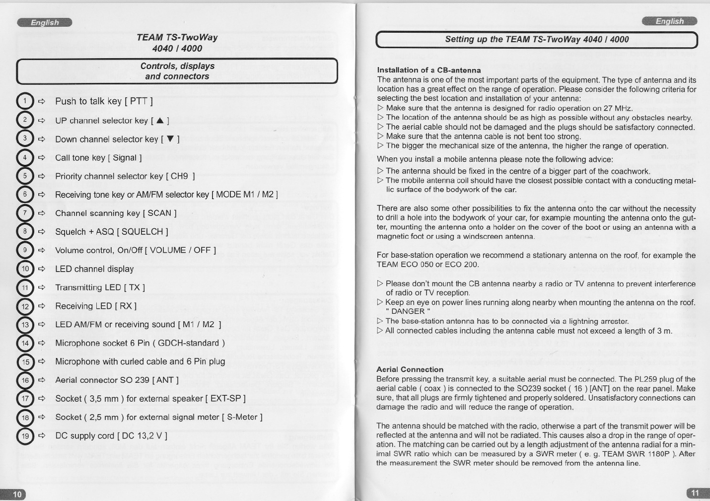
Controls, displays
and connectors
Push to talk key [ PTT ]
UP channel selector key [ Á ]
Down channel selector key [ T ]
Cali tone key [ Signal]
Priority channel selector key [ CH9
Receiving tone key or AM/FM selector key [MODE M1 / M2]
Channel scanning key [ SCAN ]
Squelch +ASQ [ SQUELCH ]
Volume control, On/Off [ VOLUME / OFF]
LED channel display
Transmitting LED [ TX ]
Receiving LED [ RX ]
LED AM/FM or receiving sound [ M1 / M2 ]
Microphone socket 6 Pin ( GDCH-standard )
Microphone with curled cable and 6 Pin plug
Aerial connector SO 239 [ANT ]
Socket ( 3,5 mm ) for external speaker [ EXT-SP]
Socket ( 2,5 mm ) for external signal meter [ S-Meter]
DC supply cord [ DC 13,2 V ]
)
Setting up the TEAM TS-TwoWay 4040 /4000
Installation of a CB-antenna
The antenna is one of the most important parts of the equipment. The type of antenna and its
location has a great effect on the range of operation. Please consider the following criteria for
selecting the best location and installation of your antenna:
l> Make sure that the antenna is designed for radio operation on 27 MHz.
l> The location of the antenna should be as high as possible without any obstacles nearby.
l> The aerial cable should not be damaged and the plugs should be satisfactory connected.
l> Make sure that the antenna cable is not bent too strong.
l> The bigger the mechanical size of the antenna, the higher the range of operation.
When you install a mobile antenna please note the following advice:
l> The antenna should be fixed in the centre of a bigger part of the coachwork.
l> The mobile antenna coil should have the c10sest possible contact with a condueting metaI-
lie surface of the bodywork of the car.
There are also some other possibilities to fix the antenna onto the car without the necessity
to drill a hole into the bodywork of your car, for example mounting the antenna onto the gut-
ter, mounting the antenna onto a holder on the cover of the boot or using an antenna with a
magnetic foot or using a windscreen antenna.
For base-station operation we recommend a stationary antenna on the roof, for example the
TEAM ECO 050 or ECO 200.
l> Please don't mount the CB antenna nearby a radio or TV antenna to prevent interference
of radio or TV reception.
l> Keep an eye on power lines running along nearby when mounting the antenna on the roof.
"DANGER"
l> The base-station antenna has to be connected via a Iightning arrester.
l> AII connected cables including the antenna cable must not exceed a length of 3 m.
Aerial Connection
Before pressing the transmit key, a suitable aerial must be connected. The PL259 plug of the
aerial cable ( coax ) is connected to the S0239 socket ( 16 ) [ANT] on the rear panel. Make
sure, that all plugs are firmly tightened and properly soldered. Unsatisfactory connections can
damage the radio and will reduce the range of operation.
The antenna should be matched with the radio, otherwise a part of the transmit power will be
reflected at the antenna and will not be radiated. This causes also a drop in the range of oper-
ation. The matching can be carried out by a length adjustment of the antenna radial for a min-
imal SWR ratio which can be measured by a SWR meter ( e. g. TEAM SWR 1180P ). After
the measurement the SWR meter should be removed from the antenna line.

Watch for the correct polarity of the DC power cable.
Solder side view of the microphone connector or top view of the microphone plug
Microphone
Plug the microphone into the 6 pin socket ( 14 lon the front panel. Note it will only go in one
way round. No transmission and receiving is possible without the microphone. The pin
assignment of the GDCH standard microphone plug is given below:
)
English
Operating of the TEAM TS-Two Way
[ M1 = AM / M2 = FM I
4. Receiving Tone [ MODE]
The type TS-TwoWay 4000 is equipped with a receiving tone key ( 6 l [MODE M1 & M2 l·
By switching on the set the receiving tone sounds bright and is indicated by LED ( 13 l[M1 ].
By pushing the mode key ( 6 lthe receiving tone is changing to a mellow sound in the loud-
speaker. When the mellow sound is switched on the LED ( 13 l[M2 ] lights up.
5. Modulation Selection [ MODE]
The type TS-TwoWay 4040 is availabe in AM / FM modulation :
• TS-TwoWay 4040 =40 channels AM / FM
By switching on the set it is always on AM mode channel 9. By pushing key ( 6 l[MODE I
the mode can be toggled between AM and FM. The selected mode will be indicated by
the LED's ( 13 l.
2. Squelch
By turning the squelch control [ SQUELCH I(8lslowly c1ockwise, the background noise
can be suppressed. The squelch control should only be turned up enough to stop the
background noise on an unused channel. Turning the control further clockwise will
increasingly suppress interfering signals as well as weak stations.
The automatic squelch [ ASQ Ican be activated by turning the squelch control counter-
c10ckwise until the control c1icks and the normal squelch function is switched off.
3. Channel Selection [T .Á. ]
AII channels can be selected by pushing the channel selector keys ( 2 l[.Á. ] and ( 3 l
[T ]at the microphone to the desired channel. The channel number will be displayed in
the LED window ( 10 l. For communication with a partner CB station, both transceivers
must be adjust to the same channel and the same mode type FM.
1. Switching On
Before switching ON set the control ( 8 l[SQUELCH Ito the counterclockwise stop. The
device is switched ON by turning the control ( 9 l[VOLUME] c10ckwise to the centre posi-
tion. The channel display ( 10 land the LED ( 12 l[RX ] light up. Adjust the receiver noise
with the volume control to the desired level. The internal S-Meter indicates the relative
received fieldstrength of incoming signals.
(
Pin assignment
Modulation
Speaker
PH
UP/DOWN
Ground
+12 Volt
PIN 1
PIN 2
PIN 3
PIN 4
PIN 5
PIN 6
Power source
Before connecting the power source to the fused DC power cable ( 19 lthe device must be
switched OFF by turning the volume control ( 9 l[VOLUME/OFF Ianticlockwise as far as the
stop and hearing a switching sound. The transceiver is designed to operate from a power
source of 13.8 volts DC, employing negative ground electricai system. For base-station oper-
ation use a suitable power supply ( 13,2 V / 2,0 A, e. g. TEAM LabNT l. The power supply
should be designed for operation with a transceiver, otherwise interference from the mains
may occur. Lay the cable as far as possible away from aggregates which can cause interfer-
ence.
->, no interference of the roadworthiness,
->, good access of the controls of the car,
->, sufficient air circulation to prevent overheating of the radio in transmit mode.
Please take into account that the LED-display is only good readable from a certain angle. An
intensive solar radiation can also affect the readability of the display. So it is recommended
to check the best position before the final installation. The unit can easily be fixed onto dif-
ferent positions in the car by using the enclosed mounting bracket.
~~
Installation
Always mount the transceiver where the switches are easy accessible. Important points of
view for the correct mounting position are:
BLACK connect to - MINUS / ground of the car battery.
RED connect to 12 volts + PLUS of the car battery.
The type TS-TwoWay 4000 is equipped according to the European Telecommunication
Standard ETS 300 135 with 40 channels FM only.
After microphone, aerial and power source have been correctly connected, radio operation
can be undertaken.
6. Transmitting [ PTT ]
To transmit depress and hold the key [ PTT] (1 ). The TX control LED ( 11 ) lights up in red
colour. The sensitivity of the microphone ( 15 ) has been set to give good results speaking
normally at a distance of 2 - 4 inches. Speaking too loudly will cause distortions and make
the signal difficult to understand. While the set is in the transmit mode there is no key entry
possible and the receiver is muted. On completion of the transmission release the PTT key
and the set will revert to receiving mode. The RX LED ( 12 ) now lights up in green colour.
7. Channel Scanning [ SCAN ]
Before selecting the SCAN function set the squelch control [ SQUELCH ] ( 8 )according
to Para" 2 " because this function does not work with unmuted receiver. Depress now the
key [ SCAN ] ( 7 ). In the display the channels arestepping upwards. SCAN stops on the
first occupied channel, where a signal can trigger the squelch threshold. The SCAN func-
tion is terminated now.
8. Channel 9 [ CH9 ]
The priority channel 9 can be quickly selected by pressing the key [ CH9 ] ( 5 ). The chan-
nel number 9 lights up in the channel LED-display. No other funetion except transmitting
can be entered as long as the CH9 function is switched ON. Pressing CH9 again will can-
cel the function and the unit returns to the previous selected channel.
9. Cali Tone
lf you press the cali key ( 4 ) a cali tone will be transmitted and can be heard by the partner-
station providing it is switched on the same channel and same mode.
10. External Speaker Jack [EXT-SP]
The TS-TwoWay has a 3.5 mm phone socket ( 17) on the rear panel to conneet an exter-
nal speaker of 4 - 8 ohm impedance. AtA ohms the speaker load can be up to 4 watts
( e.g. TEAM TS-500 ). When the external speaker is connected the internal speaker will
be switched off.
11. External Signal Meter Jack [S-METER]
The TS-TwoWay offers also on its rear panel a socket ( 18 ) [ S-METER] to conneet an
external S-meter with a 2.5 mm plug. Please note that the external S-meter shows only
the relative fieldstrength of the incoming signal. The signal strength of a received station
can be either measured with a S-meter or estimated by the own impression. For the eval-
uation of the received signal there are 9 S-steps available. One S-step more is the same
as an increase of 6 dB. This means that the input signal strength at S3 is twice as high as
at S2. The 5 R-values can be used to inform the counter station about the sound quality
of the transmission.
Specifictions are subject to change without any prior notice or obligation on the part of the manufacturer.
English
Safety Instruction
Drivers must keep attention about traffic rules by using the transceiver in a vehicle. Drivers
should use a handsfree microphone while driving.
The unit radiates RF energy in transmit mode. Please keep an eye on safety distance to
the antenna.
Servicing
The device must not be opened. Independent repairs or adjustment must not be carried out,
since each modification or unauthorised intervention will result in the cancelling of the oper-
ating permit and of the guarantee and repair claims.
Do not use the set if it seems not to function correctly. Disconnect the set from the DC power
source immediately. If there is a defect, the authorised TEAM specialist dealer or TEAM
must be contacted in eve ry case.
General Precautions
Protect the set from humidity and dust. Do not store at places or in the sun where the tem-
perature may rise and cause damage. The set can be cleaned by wiping with a soft cloth.
Do not use chemical products to c1ean the set.
Approvals
The type TS-TwoWay 4000 is approved according to the European standard ETS 300 135.
It is intended to be put into circulation in the following european countries: Austria, Belgium,
Croatia, Czech Republic, Denmark, Finland, France, Germany, Hungary, Italy, The
Netherlands, Norway, Lithuania, Luxemburg, Repulic of Slovenia, Spain, Sweden,
Switzerland, United Kingdom.
The type TS-TwoWay 4040 is additionally approved under ETS 300 433. The type TS-
TwoWay 4040 is approved for use in Switzerland only. TS-TwoWay 4040 is for distribution
and sale in: Belgium, Finland, France, Germany, Poland, Portugal, the Netherlands,
Republic of Slovakia
This manual suits for next models
1
Other Team Radio manuals


