TEC Electronics Prizrak 510 Manual

510
TECHNICAL
SPECIFICATION
INTELLECTUAL
SYSTEM
theft prevention
PRIZRAK

2
Table of Contents
Chapter I. Immobilizer Description
Introduction
Prizrak-510 intellectual theft prevention system (hereinafter referred
to as Immobilizer) is designed for vehicle theft prevention should
such an incident occur while the vehicle is parked or should hijack-
ing be the case. Besides, the Immobilizer is equipped with additional
service features: Comfort feature control, electro-mechanic hood lock
control and central locking control.
In order to receive information on Immobilizer connection to a given
vehicle and on the list of vehicles compatible with the Immobilizer along
with information on its functionality please use Integrator software
product les (hereinafter referred to as Integrator les).
Terms
Programming button – one of original buttons of the vehicle
used for programming the immobilizer (see Integrator les for infor-
mation on which button is used in each given vehicle). When using
the Immobilizer, the Programming button is not redened. The but-
ton can be redened only during the installation of the Immobilizer
in the vehicle. The button integrated in the Integrator files’ case
can be used as Programming Dutton.
Security – it is the condition of Immobilizer that is entered by locking
the vehicle’s doors in any way provided by the vehicle manufacturer
(with the lock cylinder on driver’s door, keyless access system, remote
control, or re-arming etc.) that includes arming of the original vehicle
alarm. Secure condition is left by unlocking the doors with the origi-
nal remote control or vehicle keyless access system and by entering
the PIN code.
Comfort feature – is the original function that allows not only lock-
ing vehicle’s doors but also closes the vehicle’s windows (possibly with
the sun roof) with the original remote control and (or) with the key.
Speed control – allows setting the locking activation algorithm
for Immobilizer and Anti HiJack features. Speed control can be activated
and de-activated in user settings programming menu. Certain vehicles
may not support this feature (please see Integrator les for details).
Guard mode – is an active operation mode of Immobilizer and Anti
HiJack features: should one of these features enter the Guard mode,
it is necessary to enter the correct PIN code; otherwise the Engine
locking will occur.
Engine locking – is the locking and preventing the vehicle’s engine
from operation with help of a relay.
PIN and PUK codes
PIN code
PIN code is a secret combination of original vehicle button(s) press-
ings. Please see the Integrator les for the list of original buttons
perceived by the Immobilizer. PIN code needs to be entered prior
to driving the vehicle.
PIN code is a one-, two-, three- or four-digit number. Each digit is
a gure from 1 to 9.
PIN code can be promptly changed numerous times by both technical
specialists during Immobilizer installation or by you during day-to-day
vehicle use
Factory default settings:
PIN code – 2 is entered with the Programming button – see Inte-
grator les. Upon Immobilizer installation the factory-set PIN code
is to be changed for the purposes of providing the proper secrecy
level. If the PIN code is not changed, a beep tone will be ac-
tivated after factory-set PIN code entering in order to remind
the necessity of PIN code changing.
PUK code
In case if the vehicle owner loses the PIN code, the Immobilizer
supports the entering of the PUK code.
PUK code completely replaces the PIN code but cannot be changed
during operation.
PUK code is located under the protective layer on the plastic card.
PUK code entering is carried out by Programming button with 2-second
pause after each digit. PUK code can be entered with the integrated
Programming button and with the original vehicle button assigned
as the Programming button
Only the vehicle owner must know the PUK code
Upon successful PUK code entering a new PIN code can be programmed
PIN code entering
PIN code is entered with vehicle ignition and engine on by steadily
pressing the original vehicle’s buttons. When entering one of the PIN
digits, please make sure that pressing or pause duration is no longer
than 1 second.
Please keep the pause of approximately 2 seconds in between
the digits. If you made a mistake while entering the PIN code, please
wait for longer than 3 seconds and re-enter the PIN code.
PIN code entering sequence
◊ Turn the ignition and engine on Enter the PIN code
◊ Wait for audible conrmation trill
Chapter I. Immobilizer Description
Introduction............................................................................. 2
Terms......................................................................................2
PIN and PUK codes................................................................... 2
PIN code ......................................................................2
PUK code .....................................................................2
PIN code entering .................................................................... 2
Available PIN code options ........................................................3
Immobilizer feature .................................................................. 3
Anti HiJack feature ...................................................................3
Maintenance mode ...................................................................3
Additional features ................................................................... 4
Comfort feature control ................................................. 4
Electro-mechanic hood locks control ............................... 4
Central locking control................................................... 4
Chapter II. Connection
Immobilizer Inputs/Outputs.......................................................4
Table 1. Immobilizer port description .............................. 4
Immobilizer pin connectors’ description ...................................... 4
PRIZRAK-510 Immobilizer connection diagram (factory default
settings)..................................................................................5
Chapter III. Programming
Immobilizer programming .........................................................5
Programming stage one. Immobilizer interfacing with
the vehicle. 5
Identifying the vehicle model ......................................... 5
Analog steering wheel buttons programming ................... 5
Programming stage two. Immobilizer conguration
programming 6
Table 2. Programming menu ..........................................6
Immobilizer hardware features programming (Menu 1)................ 6
Table 3. Hardware features programming (Menu 1).......... 6
Annotations to Table 3................................................... 6
Programming sequence ................................................. 6
Table 4. CAN bus adapter functions ................................ 7
Immobilizer user settings programming (Menu 2)........................ 8
Table 5. Immobilizer user setting conguring (Menu 2)..... 8
Annotations to Table 5................................................... 8
Programming sequence ................................................. 8
PIN code changing ...................................................................9
Programming button changing...................................................9
Programming examples.............................................................9
Resetting to factory default settings........................................... 9
Chapter IV. Standard delivery package and technical
characteristics
Standard delivery package ...................................................... 10
Technical characteristics.......................................................... 10

3
Available PIN code options
, , , , - buttons are used as an example. Please refer to the Integrator software les for the list of buttons perceived by the unit.
Single-button PIN code entering
One-digit PIN code: Two-digit PIN code:
~2 second pause
Multiple buttons PIN code entering
When entering the PIN code you need to keep in mind the button pressing sequence.
One-digit PIN code: Two-digit PIN code:
~2 second pause
Immobilizer feature
Immobilizer feature is designed for preventing the vehicle from being
stolen from its parking area. Immobilizer enters the Guard mode when
the ignition is turned off for longer than 30 seconds. If the Immobi-
lizer feature is in Guard mode then it is necessary to enter the correct
PIN code otherwise the engine will be locked:
◊ The engine will be turned off right after the vehicle
starts moving if the Speed control is on and is supported
by the vehicle.
◊ The engine will be turned off within 5 seconds after
the ignition has been turned on if the Speed control
is off or is not supported by the vehicle.
Immobilizer can leave the Guard mode and the engine lock can be un-
locked by entering the PIN code without turning the ignition off prior
to the procedure.
You do not need to enter the PIN code again if the ignition has been
off for less than 30 seconds.
Anti HiJack feature
Anti HiJack is the function that prevents the vehicle from being
hijacked or stolen from its parking area.
Anti HiJack enters the Guard mode in the following cases:
◊ The ignition has been turned off for longer than 30 seconds
(in case if Immobilizer feature was not on; if it was on then
the Immobilizer will follow its algorithms).
◊ Driver’s door has been opened.
Upon entering the Guard mode, Anti HiJack feature passes a sequence
of phases and in case if the Guard mode has not been deactivated,
the feature will activate the Engine locking.
Changing of phases takes place only when the ignition is on. When
ignition has been turned off the Immobilizer will save its current condition
and will continue its operation when the ignition is back on.
Anti HiJack’s Guard mode can be deactivated at any phase by enter-
ing the PIN code.
Guard mode includes the following phases:
◊ Idle phase
◊ Alarm phase
◊ Locking phase
Idle phase
In this phase Anti HiJack follows two different algorithms depending
on the availability of Speed control.
If the Speed control is available, Anti HiJack waits until the vehicle
covers a set distance from the moment of Guard mode activation. Upon
that, Anti HiJack goes into the Alarm phase.
If the Speed control is not available, Idle phase consists of three stages:
◊ Waiting for driver’s door closing
◊ Waiting for a certain number of brake pedal pressings
◊ Pause before Alarm phase initiation
Alarm phase.
This phase consists of two stages:
◊ Driver warning on the necessity of entering the PIN code
(10 seconds). It is carried out by an audible sound alert.
◊ Warning the other drivers on the road on the possible
hazardous situation due to the upcoming engine locking
(10 seconds). It is carried out by vehicle hazard lights
warning the other drivers.
If at any of the stages mentioned above attempts of entering the PIN
code shall occur, the stage’s duration may be increased up to 20 sec-
onds, but the overall phase duration cannot be longer than 30 seconds.
Locking phase.
Engine locking is activated. Hazard lights will be on for 15 seconds.
Anti HiJack will be in the locking phase until the PIN code is entered.
When safe locking mode is on (see Immobilizer hardware
settings programming (Menu 1) section), Engine locking will
be activated only if the vehicle’s speed is 30 km/h or less.
If the vehicle speed exceeds 30 km/h the Immobilizer will wait
for speed decrease for an unlimited amount of time (while
the vehicle is moving). As soon as the speed goes as low as
30 km/h the immobilizer will lock the engine
Use of safe locking mode allows mitigating the risk of collisions when
Engine locking is activated.
When the ignition is off Anti HiJack turns the hazard lights and au-
dible driver warning signals off. If the Immobilizer feature has not
entered the Guard mode (see the Immobilizer feature section) then,
upon the next ignition activation Anti HiJack will activate audible driver
warning and hazard lights for 15 seconds. In the meantime Anti HiJack
feature allows starting the engine but will prevent driving following
the same algorithms as Immobilizer feature.
If the Immobilizer feature has entered the Guard mode, then, upon
ignition’s deactivation Anti HiJack feature will stop its operation and Im-
mobilizer will follow the algorithms of Immobilizer feature.
Maintenance mode
Maintenance mode is an operation mode when all theft prevention
and service functions of Immobilizer are temporarily deactivated.
With Maintenance Mode on, entering the PIN code is not needed when
driving the vehicle, which is helpful when the car needs to be put for
maintenance in the service center. Still, in order to enter the Program-
ming mode, it is necessary to enter the PIN code.
When the ignition is turned on in Maintenance mode, a long audible
tone is sounded that reminds on the fact that the Immobilizer is in
maintenance mode. The audible tone can be turned off for secrecy
level increase.
In order to activate or deactivate the Maintenance mode you need
to do the following:
1 Turn the ignition on Enter the PIN code and wait for conrmation
2 Press and release the Programming mode button 6 times (start
doing it no later than 10 seconds after PIN code entering).Please
wait for conrmation that you have successfully performed
the actions:
◊ 1 audible signal and 1 sound trill mean that the Mainte-
nance mode is ON.
◊ 2 audible signals and 1 sound trill mean that the Main-
tenance mode is OFF.
3 Turn the ignition off.
4
Additional features
The Immobilizer has additional features improving the vehicle se-
curity level.
Comfort feature control
The Immobilizer can be programmed so that the vehicle’s windows
are closed when the vehicle’s security is Armed. Please see Integrator
les for supported vehicles.
Electro-mechanic hood locks control
The Immobilizer allows closing an accessory hood lock simultane-
ously with vehicle locking and opening the hood lock when the PIN
code has been entered.
Central locking control
If the vehicle is not equipped with the following functions:
◊ Doors locking during driving
◊ Doors unlocking upon turning the ignition off They
can be carried out by the Immobilizer. Please see Integra-
tor for list of supported vehicles.
Chapter II. Connection
Immobilizer Inputs/Outputs
Immobilizer Inputs / Outputs functionalities are described in the Im-
mobilizer port description Table. Connection pin numeration is indicated
on g. 1. Aside from outputs with set functions Immobilizer is equipped
with two programmable outputs each of which can be assigned with
one of 20 functions (see CAN bus adapter features table). These outputs
are set for controlling an accessory hood lock. Output conguration
is carried out via programming (see Immobilizer hardware functions
programming (Menu 1)).
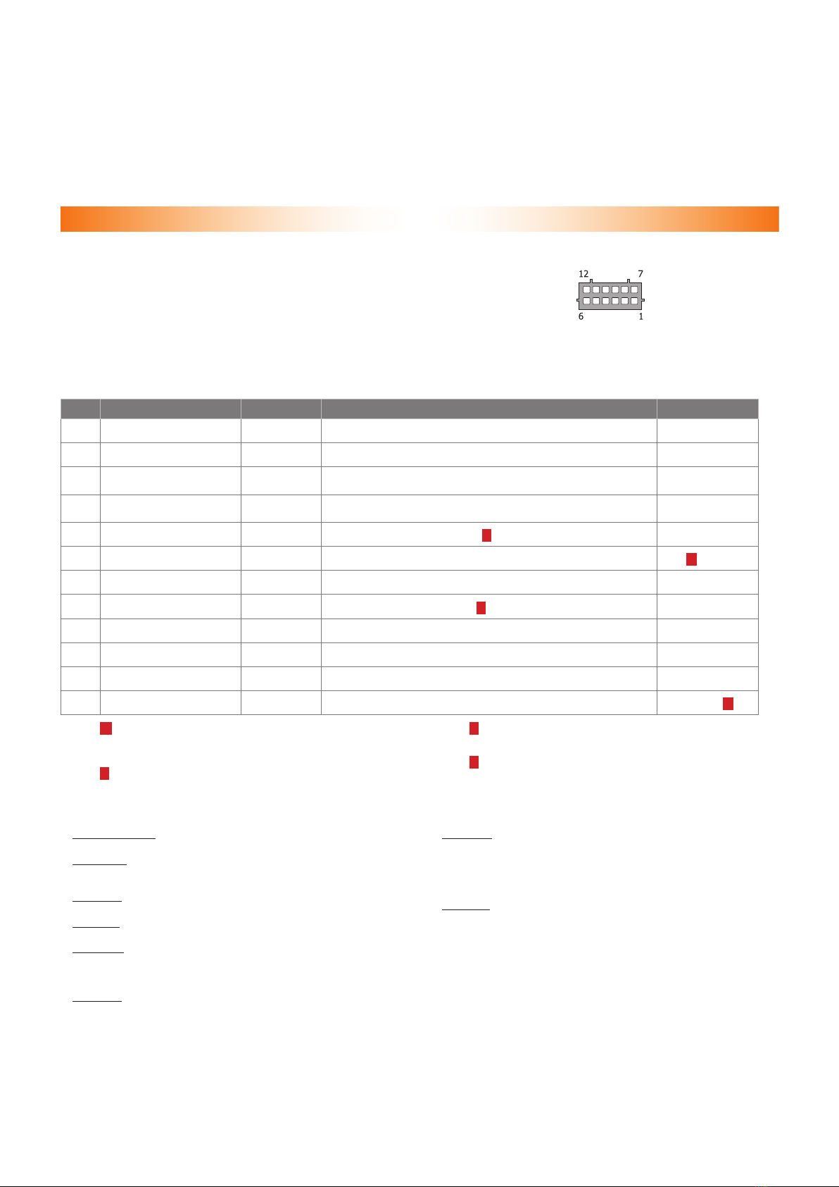
Fig. 1. Port connector pins
enumeration from wir-
ing viewpoint
Table 1. Immobilizer port description
No. Color Type Function Current, mA
1Brown/red CAN CAN-H vehicle data bus –
2 White/black - output Engine locking 150
3 Gray/green - output Programmable negative output (Arming impulse by default) 50
4 Gray/blue - output Programmable negative output (PIN code entering impulse
by default) 50
5 Blue/red +/- output Alternate hazard lights control 1) 150
6 Black power supply Ground – 2)
7 Brown CAN CAN-L vehicle data bus –
8 Pink/Green + input Brake lights condition control 3) 1,5
9- - - –
10 Gray/yellow + input Analog button/Positive button –
11 Gray/black - input Reference ground/Negative button –
12 Red power supply +12 V 200(3,5) 4)
1) – Is an output with convertible electrical polarity. Polarity
is set automatically upon unit interfacing with the vehicle. This
output is used for alternate hazard lights control in vehicles
that do not support CAN bus control.
2) – Useful current of output No. 6 depends on connected load
of the negative outputs
3) – Input No. 8 is to be connected only in vehicles where CAN bus
does not contain data on brake pedal position (see Integrator
les).
4) – Maximum useful current rate in transfer and idle modes
is indicated.
Outputs No. 2, 3, 4 are protected from short circuit, inductive erup-
tions, overheating and maximum demand surpassing.
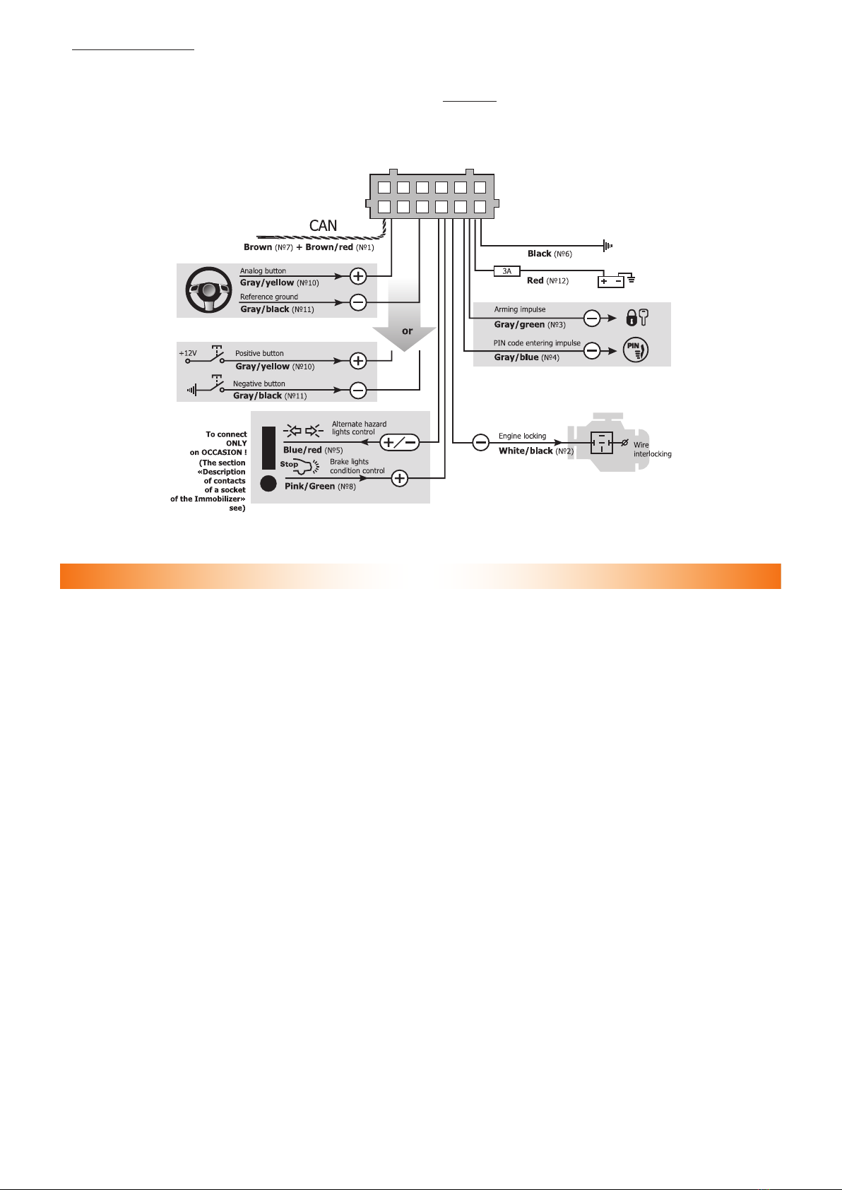
Immobilizer pin connectors’ description
Pins No. 1 and 7. “CAN-H and CAN-L vehicle data bus” are connected
to vehicle CAN bus (see “Integrator les”).
Pin No. 2. “Engine lock” is connected to one of relay coil con-
tacts, which is used for engine operation or ignition lock. The output
can be set for controlling a normally-open or normally-closed relay.
Pin No. 3. Programmable negative output (“Arming impulse” by de-
fault).
Pin No. 4. Programmable negative output (“Vehicle PIN code entering
impulse” by default).
Pin No. 5. “Alternate hazard light control” is used for hazard light
controlling on vehicles where CAN bus control is not available. Please
see Integrator les software product for information on vehicle-specic
connection features.
Pin No. 6. “Ground” is connected to vehicle body in one of the loca-
tions determined by vehicle manufacturer for original equipment ground
connection.
Pin No. 8. “(+) Input” brake lights control. It is used only in cases
when vehicle CAN bus does not contain data on brake pedal position
(see Integrator les). In such cases input No. 8 is to be connected
to brake pedal terminal switch output. Should the CAN bus contain
brake pedal position data the input’s function is lost and can be re-
stored only when settings are reset to factory default ones.
Pin No. 9. is not in use Pin No. 10. “(-) Input. Analog button/Positive
button”. Depending on control button type choice one of the following
functions is used:
◊ Analog button is connected to the corresponding vehicle wire
at the steering wheel contact helix port (see Integrator les).
◊ Positive button is connected to the positive button (the
one controlled by +12V voltage). It is used in case if there
are no original vehicle buttons perceived by the Immobilizer.
If the vehicle has original buttons controlled via CAN bus that are per-
ceived by the Immobilizer, this input may be discarded.
5
Pin No. 11 (-) input. Depending on control button choice
one of the following functions is used:
◊ Analog button is connected to the corresponding vehicle
wire at the steering wheel contact helix port (see Inte-
grator les).
◊ Negative button is connected to the negative but-
ton (the one controlled by ground fault). It is used
in case if there are no original vehicle buttons perceived
by the Immobilizer.
If the vehicle has original buttons controlled via CAN bus that are per-
ceived by the Immobilizer, this input may be discarded.
Pin No. 12. Immobilizer power supply is connected through 3 A fuses
to one of vehicle wires that has +12 V non-commutated voltage.
PRIZRAK-510 Immobilizer connection diagram (factory default settings)
Chapter III. Programming
Immobilizer programming
Immobilizer programming is carried out with Programming button.
Programming stage one. Immobilizer interfacing with
the vehicle.
Identifying the vehicle model
Vehicles supported by the Immobilizer are divided into functional
groups, each of which is divided into subgroups. All groups and sub-
groups are assigned with item ordinals (see Integrator les). Interfacing
is the procedure of Immobilizer detecting vehicle group and subgroup.
There are two interfacing options:
1
Automatic interfacing.
In order to automatically interface the Immobilizer with the ve-
hicle it is necessary to carry out a set of actions (see Integrator
les). Upon vehicle identication algorithm is launched the Im-
mobilizer emits a constant audible signal.
If the Immobilizer identies only the vehicle group, then it will
stop emitting the constant signal and will periodically emit series
of audible signals, where the number of signals will correspond
with the group number.
If the Immobilizer identies both the group and subgroup
of the vehicle, then it will inform on the completion of vehicle
interfacing with an audible sound trill and will emit three
series of audible signals where the number of long signals
corresponds with the group number and the number of short
signals corresponds with the subgroup number.
2
Forced interfacing.
This algorithm is used in extraordinary cases.
Programming is carried out with the integrated Programming
button. Prior to interfacing procedure initiation vehicle group
must not be identied and CAN bus must not be connected. Pro-
gramming will stop if Programming button shall not be pressed
within 60 seconds.
Programming sequence:
2.1 Power the Immobilizer and wait for discontinuous signal.
2.2 Enter Menu 1 by pressing and releasing the Programming
button 10 times (this needs to be done no later than 10
seconds after the system has been powered). If the pro-
cedure is carried out correctly, the Immobilizer will inform
on this fact with three audible signals.
2.3 Enter menu option No. 1 – Vehicle model – by pressing
the Programming button once. The Immobilizer will inform
on option condition with 1 audible signal series.
2.4 Enter the vehicle’s group number by pressing the Program-
ming button for the corresponding number of times (see
Integrator les). The Immobilizer will periodically emit series
of audible signals where the number of signals corresponds
with the group number.
2.5 Enter the vehicle’s subgroup number by pressing the Pro-
gramming button for the corresponding number of times
(see Integrator les).
Verify that the vehicle model has been chosen correctly with help of audible
signals (group number – pause, subgroup number – pause):
◊ If the vehicle model has been chosen correctly, press
the Programming button once. Audible signals will stop
and the vehicle model will be programmed.
◊ If the vehicle model has been chosen incorrectly, then
press the Programming button twice. Repeat the program-
ming procedure beginning from p. 2.4.
Analog steering wheel buttons programming
In order to use the analog steering wheel buttons please do as follows:
◊ Right after the Immobilizer identies the vehicle model,
turn the ignition on and wait for no less than 5 seconds.
◊ Press all the steering wheel and steering wheel column
joysticks’ buttons (cruise control, central unit control etc.)
sequentially (one after another). The buttons, upon press-
ing of which and audible signal will be heard, are available
for use.
◊ Turn the ignition off; an audible sound trill will
be played.
◊ Turn the ignition on.

6
◊ Assign the Programming button from available ones
by pressing and holding it for no less than 5 seconds
(until an audible signal will be heard).
Programming stage two. Immobilizer conguration pro-
gramming
At stage two Immobilizer hardware functions and user settings
are changed and a new PIN code is programmed. Three independent
menus are used during programming (see Programming menu table).
Table 2. Programming menu
Name Menu entering
code
Audible signals
number Function
Menu 1 10 3Immobilizer hardware settings conguration (see page 6)
Menu 2 12 4Immobilizer user settings conguration (see page 8)
Menu 3 14 1 PIN code changing (see page 9)
Immobilizer hardware features programming (Menu 1)
Programming is carried out in accordance with Immobilizer hardware features programming (Menu 1) table.
Table 3. Hardware features programming (Menu 1)
No. Option name Setting range Factory de-
fault settings Notes
1 Vehicle model - - –
2Changes locking 1 – 4 21 - Public, 2 - OFF, 3 - User, 4 - Admin
3 Engine locking 1 – 3 2
1- normally open relay control
2- normally closed relay control
3- reserved by manufacturer
4Safe locking mode 1 – 2 21-Safe locking mode on
2- Safe locking mode off
5External buttons type 1 – 2 1 1- Outputs No. 10 and 11 are used as analog buttons
2- Output No. 10 and 11 are used as digital buttons
6Hazard lights control algo-
rithm 1 – 6 -
1- impulse negative control
2- status negative control
3- impulse positive control
4- status positive control
5- lamps control
7(-) Output No. 3 1 – 20 2 Programmable negative output (Arming impulse by default)
8(-) Output No. 4 1 – 20 20 Programmable negative output (PIN code entering impulse by de-
fault)
Annotations to Table 3
p. 1. Vehicle model allows forced selection of vehicle group and sub-
group.
p. 2. Change locking allows prohibiting the Immobilizer hardware
features reprogramming.
This point has 4 conditions:
1 Public – reprogramming prohibition is set for all menu options
except for 2;
2 OFF – prohibition is removed and all options
can be reprogrammed;
3 User – prohibition is set for all the options aside from 1. Pass-
word needs to be entered in order to remove prohibition (see
below);
4 Admin – prohibition is set for all menu options. Password needs
to be entered in order to remove prohibition.
Settings 1 (Public) and 2 (OFF) can be set with Programming button.
Settings 3 (User) and 4 (admin) and the password can be set only
while programming the Immobilizer with a PC or TECPROG original
programming unit. User or Admin prohibition can be removed only
with TECPROG upon entering the password. You can go from User
mode to Public mode in order to prohibit the reprogramming of all the
options except for 2. In this case you can go only back from Public
mode to User mode.
Resetting to factory default settings leads to resetting of only the op-
tions, reprogramming of which has not been password protected.
In any condition of option No. 2 you can access the menu, navigate
all the options and check every option’s condition.
p. 3. Engine locking allows setting the output No. 2 for normally
open relay.
p. 4. Safe locking mode. With this mode on, Engine locking will be ac-
tivated only if the vehicle speed is 30 km/h or less.
p. 5. External buttons type. Depending on the buttons used:
◊ Inputs No. 10, 11 are used for connecting analog (steer-
ing wheel) buttons
◊ Inputs No. 10, 11 are used for connecting digital (posi-
tive/negative) buttons
p. 6. Hazard lights control algorithm allows setting the required con-
trol algorithm. In the majority of cases the algorithm is set automatically
during vehicle interfacing.
p. 7. (-) Output No. 3 is a programmable negative output (Arming
impulse by default).
p. 8. (-) Output No. 4 is a programmable negative output (PIN code
entering impulse by default).
Programming sequence
1 Turn the ignition on.
2 Enter the PIN code and wait for conrmation.
3 Enter Menu 1 by pressing and releasing the Programming button
10 times (you need to do this no later than 10 seconds upon
PIN code entering). The Immobilizer will notify of menu accessed
by three sound trills.
4 Select menu option by pressing and releasing the Programming
button for the number of times corresponding with the menu
option number. The Immobilizer will inform on menu number
by series of audible signals.
5 Go to option setting by pressing and holding the brake pedal.
The Immobilizer will inform you on the option setting by series
of audible signals, and their duration will change.

7
6 Change the option setting by pressing and releasing the Pro-
gramming button for the number of times necessary for moving
from the current setting number to the required setting number
in the option (e.g., in order to change function No. 2 (Arming
impulse) with function No. 16 (External lights) you need to press
and release the programming button 14 times. The Immobilizer
will inform on the new option setting with series of audible sig-
nals. It is necessary to consider that during navigation in the op-
tion the rst number goes after the last one. Release the brake
pedal; the Immobilizer will indicate the current setting and then
the current menu option number. Now you can proceed with
programming the next option and leave the programming mode.
6.1 Function No. 7 Doors, hood and trunk programming algo-
rithm (applicable only for options No. 7 and 8 of Menu 1).
6.1.1 Set any combination of doors, hood and trunk, the open-
ing of which will cause the Immobilizer to form a signal
on the programmable output. For the purposes of this descrip-
tion doors, hood and trunk are simple referred to as doors.
6.1.2 With the brake pedal pressed go to option number 7
settings. Immobilizer will inform on option condition twice
with series of 7 audible signals, after which it will start
emitting irregular audible signals. When you hear irregular
audible signals, release the brake pedal. The Immobilizer will
continue emitting irregular audible signals. Open the doors
that are to be identied on this output, the rest are to be
closed (you can open the doors in advance). Press the brake
pedal again. Immobilizer will inform on option setting change
with series of 7 signals and the doors will be assigned to this
output. If the brake pedal is not pressed and current option
programming is left, the Immobilizer will save its previous
condition. Release the brake pedal and the Immobilizer will
go to option number indication.
6.2 Function No. 8 Original buttons programming algorithm
(applicable only for options No. 7, 8 of Menu 1).
6.2.1 With the brake pedal pressed go to option number 8
settings. Immobilizer will inform on option condition twice
with series of 8 audible signals, after which it will start emit-
ting irregular audible signals. When you hear irregular audible
signals, press the required button while holding the brake pedal
(for the list of buttons of the given model, please see Integra-
tor les). If the Immobilizer has perceived the button, it will
stop emitting irregular audible signals and will start indicating
the option setting number with series of 8 audible signals.
Release the brake pedal, the Immobilizer will indicate menu
option number. If the brake pedal is released prior to the but-
ton is pressed, the Immobilizer will save its previous condition
and will start indicating the menu option number.
6.3 Function No. 9 Transmission condition programming algo-
rithm (applicable only for options No. 7, 8 of Menu 1).
6.3.1 6.3.1. With the brake pedal pressed go to option num-
ber 9 settings. Immobilizer will inform on option condition twice
with series of 9 audible signals, after which it will start emit-
ting irregular audible signals. When you hear irregular audible
signals, change the transmission to the required position: P, N,
D*or R (transmission handle can be set in the necessary posi-
tion in advance); for robotized transmission the positions are
R, N, D
*; for manual transmission only R position is available.
Release and press the brake pedal again. The Immobilizer will
stop emitting irregular audible signals and will start indicating
the option setting number with series of 9 audible signals.
Release the brake pedal, the Immobilizer will indicate menu
option number. If the brake pedal is released prior to the but-
ton is pressed, the Immobilizer will save its previous condition.
7 7. In order to go to next menu option programming press
and release the Programming button for the number of times
necessary for navigation from the required option (e.g., in order
to navigate from option No. 2 to option No. 8 in Menu 1 press
and release the Programming button 6 times). Important note:
when navigating menu options, the rst option follows the last
one.
Exiting the programming mode. The Immobilizer will exit program-
ming mode and save all conguration settings in energy independent
memory when ignition is turned off or within 60 seconds after last
menu action if the brake pedal is released.
* — all handle positions for vehicle advancement (D, S, M, L etc.).
Table 4. CAN bus adapter functions
Function Function description
No. Name
1Security Constant level signal is formed while Immobilizer is in Security mode
2 Arming impulse 0.8 second long impulse is formed when Immobilizer is entering the Security mode
3 Disarming impulse
0.8 second long impulse is formed when Immobilizer is leaving the Security mode
4Original alarm system
panic
Constant level signal is formed while the original car alarm (if the vehicle is equipped with it) is in alarm
mode.
5 Siren panic
30 seconds long constant level signal is formed if one of the following zones is triggered: doors opening,
hood opening (if CAN bus has the corresponding data or input No. 8 is connected), trunk. The func-
tion can be applied in vehicles that are not equipped with original alarm system. The signal stops when
vehicle is not in Security mode any longer.
6 Claxon panic
30 seconds long constant level signal is formed if one of the following zones is triggered: doors opening,
hood opening (if CAN bus contains the corresponding data or input No. 8 is connected), trunk. The func-
tion can be applied in vehicles that are not equipped with original alarm system. The signal stops when
vehicle is not in Security mode any longer. This feature is used for sending an alert signal to the original
vehicle claxon.
7 Doors, hood and trunk Constant level signal is formed if one of preset doors, hood (if CAN bus contains the corresponding data
or input No. 8 is connected) or trunk is opened.
8 Original buttons Constant level signal is formed if the preset vehicle button is pressed (see Integrator les application).
9 Transmission condition
Constant level signal is formed if transmission handle is set in preliminarily programmed position (P, R,
N, and D). For robotized transmission the positions are R, N, D; for manual transmission only R position
is available.
10 Sensor ignoring
Constant level signal is formed when the trunk is open in Security mode if the trunk has been opened
with the original remote control. Also the signal is formed for the purposes of Comfort function.
The function’s purpose is to deactivate the sensors in order to prevent false alarms.
11 Ignition Constant level signal is formed when ignition is turned on (including engine starting).
12 ACC
Constant level signal is formed when vehicle ACC are on (1st key position, may match with ignition
on certain vehicles). It is turned off only when the ignition key is out of ignition lock. Can be used
for correct accessory multimedia system power management.
13 Engine on Constant level signal is formed when the engine is on.
14 Vehicle is moving Constant level signal is formed if the vehicle speed has exceeded a certain threshold value (depends
on vehicle and varies in the range of 5 to 10 km/h).
15 Brake Constant level signal is formed when the brake pedal is pressed.

8
Function Function description
No. Name
16 External lights Constant level signal is formed when the external lights are on.
17 Engine rpm
Impulse signal is formed. Its impulse sequence frequency is proportional to the engine crankshaft rota-
tion frequency. 1 impulse per second corresponds with 20 crankshaft rpm. The signal’s purpose is to
determine the approximate and not precise rpm value.
18 Movement speed
Impulse signal is formed. Its impulse sequence frequency is proportional to the vehicle speed. 1 impulse
per second corresponds with 1 km/h speed. The signal’s purpose is to determine the approximate
and not precise speed value.
19 Parking brake Constant level signal is formed when the vehicle is on hand brake.
20 PIN code entering impulse 0.8 second long impulse is formed when the correct PIN code has been entered and in Maintenance
mode 1 second after ignition has been turned on even if the PIN code had not been entered.
Immobilizer user settings programming (Menu 2)
Programming is carried out in accordance with table Immobilizer user settings conguring (Menu 2).
Table 5. Immobilizer user setting conguring (Menu 2)
No. Description
Current option setting 1)
On Off Range
1Immobilizer feature On 12 —
2 Anti HiJack feature On 12 —
3 Speed control On 12 —
4 Number of brake pedal pressings 3 — — From 1 to 7
5 Anti HiJack feature response delay 1— — From 1 to 10
6PIN code entering audio conrmation On 12 —
7 Maintenance mode audio indication On 12 —
8 Central locking when driving Off 12 —
9Central lock unlocking when ignition is turned off Off 12 —
10 Automatic windows closing On 12 —
1) — number of audio signals is indicated.
Annotations to Table 5
p. 1. “Immobilizer feature” allows turning the Immobilizer feature
on or off.
p. 2. “Anti HiJack feature” allows turning the Anti HiJack feature
on or off.
p. 3. “Speed control” allows setting the lock activation algorithm
for Immobilizer and Anti HiJack features.
p. 4. “Number of brake pedal pressings” allows setting the brake
pedal pressings number necessary for Anti HiJack feature responding.
If the Speed control is on, the setting of p. 4 does not affect anything.
p. 5. “Anti HiJack feature response delay” allows setting the distance
before locking (Speed control is on) or time before locking (Speed con-
trol is off). The time is set by 20 second intervals; the distance is set by
100 meter sections. For example, if the option setting is 3, then:
◊ Locking activation delay is 60 seconds;
◊ Distance before locking is 300 meters.
p. 6. “PIN code entering audio conrmation” allows turning PIN code
entering audio conrmation on or off.
p. 7. “Maintenance mode audio indication” allows turning Maintenance
mode audio indication on or off.
p. 8. “Central locking when driving” allows turning the automatic
central locking when driving feature on or off.
p. 9. “Central lock unlocking when ignition is turned off” allows turn-
ing the automatic central lock unlocking upon ignition feature deactiva-
tion on or off.
p. 10. “Automatic windows closing” allows turning automatic windows
closing during vehicle locking on or off.
Programming sequence
1 Turn the ignition on Enter the PIN code and wait for conrmation
(see PIN code entering section)
2 Enter Menu 2 by pressing and releasing the Programming but-
ton 12 times (start doing this no later than 10 seconds upon
PIN code entering). If all operations have been carried out cor-
rectly, the Immobilizer will inform on this fact by 4 audible signals
(see Programming menu table).
3 Beginning from point 4, programming algorithm is analogical
with the one described in Immobilizer hardware features con-
guration (Menu 1), except for points 6.1, 6.2, 6.3.

9
PIN code changing
1 Turn the ignition on Enter the PIN code
2 Press the Programming button 14 times. Wait for Immobilizer’s
conrmation by 1 audible signal.
3 Set the new PIN code by using any combination of buttons
perceived by the Immobilizer (see Integrator files). When
entering a new PIN code, each pressing perceived by the Im-
mobilizer is conrmed by the audible signal for further control-
ling assistance.
4 Wait for conrmation by 1 audible signal
5 Re-enter the new PIN code.
6 Wait for conrmation:
◊ 2 audible signals and a sound trill mean that the PIN code
has been changed and the Immobilizer has left the PIN
code changing mode.
◊ Sound alert means that the PIN code has not been
changed and the Immobilizer has left the PIN code
changing mode. A mistake has been made when entering
the new PIN code conrmation and it is necessary to re-
peat the PIN code changing procedure starting from p. 1.
You can exit the PIN code changing mode anytime by turning
the ignition off.
Programming button changing
1 Reset all settings to factory default.
2 Interface the Immobilizer with the vehicle.
3 If analog steering wheel buttons are used please dene them
(see above for the description of this procedure).
4 In order to assign any of the buttons perceived by the Immo-
bilizer as the Programming button, press the selected button
and hold it for longer than 5 seconds until a long audible signal
will be heard
Programming button can be assigned within 15 minutes
after Immobilizer interfacing with the vehicle.
Programming examples
Example 1
Objective: You would like to change the factory settings of the Im-
mobilizer: set output No. 2 Engine locking to control the normally
open relay.
Execution:
1 Turn the ignition on.
2 Enter the PIN code and wait for conrmation.
3 Enter Menu 1 by pressing and releasing the Programming
button 10 times. If you have performed all the actions
correctly, the Immobilizer will notify you of it with 3 audible
signals.
4 According to Immobilizer hardware functions conguring
(Menu 1) option No. 3 Engine locking is to be selected. To do
so, press and release the Programming button 3 times.
The Immobilizer will inform you on the selected menu option
number by series of 3 audible signals.
5 Enter option No. 3 by pressing and holding the brake pedal.
The Immobilizer will inform you on the option setting
by repeated double audible signals because the current
(factory set) option setting is “normally closed relay control”.
6 Select “the normally open relay control” by pressing
and releasing the Programming button twice, for the second
setting is followed by the third. The Immobilizer will inform
you on the option setting with series of 1 audible signal.
7 Exit programming mode by turning the ignition off.
Example 2
Objective: You would like to change the factory settings of the Im-
mobilizer: to increase the Anti HiJack activation distance from 100 to
300 meters.
Execution:
1 Turn the ignition on.
2 Enter the PIN code and wait for conrmation.
3 Enter the Immobilizer setting mode by pressing and releasing
the Programming button 12 times (start doing it no longer
than 10 seconds after entering the PIN code). If you have
performed all the actions correctly, the Immobilizer will notify
you of it with 4 audible signals.
4 Select the programming option for setting the Anti HiJack
activation distance. According to Table 1 “Immobilizer
settings” option No. 5 is to be selected. To do so, press
and release the Programming button 5 times. The Immobilizer
will inform you on the selected menu option number by series
of 5 audible signals.
5 Enter option No. 5 by pressing and holding the brake pedal.
The Immobilizer will inform you on the option setting
by repeated single audible signals because the current
(factory set) option setting is 1 (which stands for 100 meters
distance).
6 Change option No. 5 setting by pressing and releasing
the Programming button twice, therefore increasing
the option setting by 2 (1+2=3). The Immobilizer will inform
you on the option setting with series of 3 audible signals (300
meters).
7 Exit the setting mode by turning the ignition off.
Resetting to factory default settings
Immobilizer has a procedure of resetting the programmable settings,
where all vehicle model settings are removed from Immobilizer’s energy
independent memory and PIN code and all other programming options
are returned to factory original values.
If certain or all menu options are password protected (see Immobi-
lizer user settings programming (Menu 2), p. 2), only the options that
are not prohibited will be reset. The remaining ones will keep their
current values.
In order to reset to factory default:
1 Remove power supply from Immobilizer
2 Press and hold the integrated Programming button
3 Connect the power supply while holding the button. Immobilizer
will emit irregular audible signals.
4 Release the button and wait until the signals stop.
5 Turn the ignition on and enter the current PIN code*.
6 An audible trill will be heard, which indicates that resetting
to factory default has been completed.
7 Remove the power supply and disconnect the Immobilizer from
CAN bus.
* If the Immobilizer is not installed in the vehicle, please enter
the PUK code with the integrated Programming button.

10
Chapter IV. Standard delivery package and technical characteristics
Standard delivery package
Name Quantity, pcs
Central unit 1
Wiring harness with port 1
Compact disc 1
Connection scheme 1
User manual 1
Warranty certicate 1
Reminder card 1
Packaging 1
Technical characteristics
Parameter Value
Power supply voltage, V 9 … 15
Maximum current drain in standby mode, mA 3,5
Maximum current drain, A 200
Operating temperature °C – 40 … + 85
Storage temperature °C – 40 … + 85
Maximum relative air humidity, % 95

11

TEC-6111-4
WWW.PRIZRAK.RU
PRIZRAK. YOUR CAR’S SECRET
O
Manufactured by TEC Electronics Ltd.
The product is manufactured in accordance with TC 4372-008-78025716-11.
Certicate of conformity No. POCC RU. AB75. B00423
The product corresponds with the requirements of the following regulations:
GOST R 41.97-99 (UNECE Rules N97), GOST R 50789-95
Table of contents
Other TEC Electronics Car Alarm manuals


Popular Car Alarm manuals by other brands

Omega
Omega K9-Sombra Owner's guide & installation instructions

Cobra
Cobra 8185 User instructions

Prestige
Prestige Prestige Platinum APS 600 installation manual

Audiovox
Audiovox APS996A - Prestige Remote Security System owner's manual

CompuSTAR
CompuSTAR Pro system user manual

Avital
Avital Maxx 1 owner's guide

Falcon
Falcon Predator EVO4+2 owner's manual

Omega
Omega KEYCOUNTER KEY-3 owner's manual

Directed Electronics
Directed Electronics 555X manual

Audiovox
Audiovox Pursuit PRO-9776N Series owner's manual

Scytek electronic
Scytek electronic Precision 700 series product manual

Directed Electronics
Directed Electronics Python 881XP owner's manual


