TEC Electronics TEC-700 User manual


2
Table of contents
Introduction�������������������������������������������������������������������������������2
Terms����������������������������������������������������������������������������������������2
Alarm capabilities �����������������������������������������������������������������������2
Alarm operation algorithm �����������������������������������������������������������2
Table 1� Arming diagnostics�������������������������������������������������������2
Table 2� Trigger diagnostics�������������������������������������������������������3
PIN and PUK codes���������������������������������������������������������������������3
PIN code entering�����������������������������������������������������������������������3
PIN code entering sequence ��������������������������������������������������������3
Available PIN code options ����������������������������������������������������������4
Immobilizer feature ��������������������������������������������������������������������4
Anti HiJack feature ���������������������������������������������������������������������4
Maintenance mode ���������������������������������������������������������������������4
Alarm Inputs / Outputs ���������������������������������������������������������������5
Table 3� Alarm port description �������������������������������������������������5
Alarm pin contacts description ����������������������������������������������������� 5
Table 4� Sensors connection port description �����������������������������5
Table 5� LED connection port description �����������������������������������5
External sensors connection ��������������������������������������������������������6
Alarm programming ��������������������������������������������������������������������6
Table 6� Programming menu �����������������������������������������������������6
Alarm hardware features programming (Menu 1)���������������������������7
Table 7� Alarm hardware features programming (Menu 1) �����������7
Alarm connection diagram (original settings)���������������������������������8
Table 8� Programmable Alarm outputs functions�������������������������� 9
Table 9� Programmable Alarm inputs functions�������������������������� 10
Alarm user settings programming (Menu 2) �������������������������������� 11
Table 10. Alarm user settings conguration (Menu 2) ���������������� 11
PIN code changing ������������������������������������������������������������������� 11
Programming button changing��������������������������������������������������� 11
Programming examples������������������������������������������������������������� 12
Resetting to factory default settings ������������������������������������������� 12
Installation scheme form����������������������������������������������������������� 13
Standard delivery kit����������������������������������������������������������������� 14
Technical data and operation conditions ������������������������������������� 14
Introduction
This Technical Manual is applicable for the following Slave alarm
systems: TEC-700 & TEC-710, (hereinafter referred to as Alarm)�
◊ Immobilizer and Anti HiJack features are available only in TEC-
710
The Alarm is designed for protecting the vehicle from being stolen
from parking location and from being hijacked� The Alarm also noti-
es should the vehicle be tampered with while it is parked.
In order to receive information on Alarm connection to a given ve-
hicle and on the list of vehicles compatible with the Alarm along with
information on its functionality please use Installation help les for
installation data (hereinafter referred to as Integrator les).
Terms
Programming button – one of original buttons of the vehicle used
for programming the Alarm (see Integrator les for information on
which button is used in each given vehicle)� When using the Alarm,
the Programming button is not redened. The button can be rede-
ned only during the installation of the Alarm in the vehicle. The
button integrated in the Alarm’s case can be used as Programming
button� (see Fig� 2)
Security – it is the condition of Alarm that is entered by locking
the vehicle’s doors in any way provided by the vehicle manufacturer
(with the lock cylinder on driver’s door, keyless access system, remote
control, or re-arming etc�) that includes arming of the original vehicle
alarm� Secure condition is left by unlocking the doors with the original
remote control or vehicle keyless access system and by entering the
PIN code�
Speed control – allows setting the locking activation algorithm
for Immobilizer and Anti HiJack features� Speed control can be acti-
vated and de-activated in user settings programming menu� Certain
vehicles may not support this feature (please see Integrator les for
details)�
Guard mode – is an active operation mode of Immobilizer and Anti
HiJack features: should one of these features enter the Guard mode,
it is necessary to enter the correct PIN code; otherwise running the
Engine will be not possible�
Comfort feature – is the original function that allows not only
locking vehicle’s doors but also close the vehicle’s windows (possibly
with the roof insert) with the original remote control and (or) with
the key�
Alarm capabilities
◊ theft protection when the vehicle is parked (immobilizer feature)
◊ hijacking protection (anti hijack feature)
◊ audible and light notications on alarm triggering
◊ engine locking
◊ accessory sensors connection: angle, volumetric etc� (shock sensor
is included in standard delivery kit)
◊ trunk opening without disarming
◊ automatic windows closing when arming
◊ central locking system activation when driving / deactivation when
ignition key is removed�
Alarm operation algorithm
Arming / disarming
Alarm arming and disarming is carried out as per original vehicle
algorithms:
◊ Arming is carried out with the original remote control, driver’s
door lock and keyless access system
◊ Disarming is carried out with the original remote control, key-
less access system and by entering the PIN code�
Arming is accompanied by a single audible signal under condition
that all the doors, hood and trunk are closed� If silent arming mode is
on, there will be no audible signal�
Disarming is accompanied by double audible signal under condition
that the Alarm was not triggered while in Security mode� If silent arm-
ing mode is on, there will be no audible signal�
Arming diagnostics
Arming with a door, hood or trunk open is accompanied by three
audible signals despite of whether the silent arming mode is on or off�
Open door, hood or trunk is indicated by LED (see Arming diagnostics
table) and is ignored by the Alarm in Security mode� 3 seconds after
the door, hood or trunk is closed the ignored zone will be secured�
Table 1� Arming diagnostics
Quantity of LED light signals Active zone when arming
2Hood
3Trunk
4Doors

3
Disarming diagnostics
If the Alarm was triggered in Security mode, then you will hear four
audible signals when disarming despite of whether silent arming mode
is on or off. Triggered zones will be indicated by LED prior to rst igni-
tion activation (see Trigger diagnostics table)�
Table 2� Trigger diagnostics
Quantity of LED light signals Reason (zone) of Alarm triggering
2 Hood
3 Trunk
4 Doors
5 Sensor 1 Alarm
6 Sensor 2 Alarm
7 Sensor 1 Warning
8 Sensor 2 Warning
9 Protection of public order
Alarm triggering
In the Security mode, the Alarm can react to actions with your vehicle
in two ways: Warning and Alarm� The Warning triggers when there
are weak effects on the shock sensor, e�g� due to vibrations caused by
passing transport� In this case the siren emits several short signals�
Alarm signal is activated if any of the doors, hood or trunk were opened
and when there was a strong effect on shock sensor� Siren will be on for
30 seconds and hazard lights will blink�
Protection of public order function
If the alarm has been triggered three times in one hour via the
shock sensor, the Alarm will stop responding to the sensor� The Alarm
will continue responding to the sensor only after the effects on the
sensor will not repeat within an hour or if the Alarm was disarmed and
rearmed� This function is not part of Warning mode�
Arming with sensors inputs deactivation
If one of kit sensors is installed:
◊ Arm the vehicle
◊ Rearm the vehicle within 3 seconds� The siren will emit one long
and one short signal: the Warning input will be deactivated�
◊ Within the next 3 seconds rearm the vehicle� The shock sensor
will be completely deactivated
If other sensors are installed:
◊ Arm the vehicle�
◊ Rearm the vehicle within 3 seconds� The siren will emit one
long and one short signal: Sensor input No� 1 will be deacti-
vated (if silent arming mode is on, the siren will emit only one
short signal)�
◊ Next arming (within 3 seconds) will deactivate both sensor in-
puts: sensor input No� 1 and sensor input No� 2� The siren will
emit one long and two short signals (if silent arming mode is
on, the siren will emit only two short signals)�
Automatic windows closing when arming
Several seconds (1 to 3 depending on vehicle model) after arming,
the Alarm activates the Comfort feature of the vehicle� Sensors out-
puts are ignored for all the time of sensor inputs operation�
Trunk opening without leaving the Security mode
When opening the trunk with remote control in Security mode ac-
cessory external sensors’ inputs are temporarily deactivated (sensor
input No� 1 and sensor input No� 2 – see Alarm inputs/outputs sec-
tion)�
Central locking control
The Alarm has automatic central locking activation when driving be-
gins (when vehicle speed exceeds 5 km/h) and central locking deactiva-
tion when the key is removed from ignition� If the vehicle has analogi-
cal original functions, it is strongly recommended to use them and keep
the corresponding Alarm functions deactivated�
PIN and PUK codes
PIN code
PIN code is a secret combination of original vehicle button(s) press-
ings. Please see the Integrator les for the list of original buttons
perceived by the Immobilizer� PIN code needs to be entered prior to
driving the vehicle�
PIN code is a one-, two-, three- or four-digit number� Each digit is
a gure from 1 to 9.
PIN code can be promptly changed numerous times by both techni-
cal specialists during Immobilizer installation or by you during day-
to-day vehicle use�
Factory default settings
PIN code – 2 is entered with the Programming button – see In-
tegrator les. Upon Alarm installation the factory-set PIN code
is to be changed for the purposes of providing the proper se-
crecy level� If the PIN code is not changed, a beep tone will be
activated after factory-set PIN code entering in order to remind
the necessity of PIN code changing�
PUK code
In case if the vehicle owner loses the PIN code, the Alarm supports
the entering of the PUK code�
PUK code completely replaces the PIN code but cannot be changed
during operation�
PUK code is located under the protective layer on the plastic card�
PUK code entering is carried out by Programming button with 2-sec-
ond pause after each digit� PUK code can be entered with the in-
tegrated Programming button and with the original vehicle button
assigned as the Programming button�
Only the vehicle owner must know the PUK code�
Upon successful PUK code entering a new PIN code can be pro-
grammed�
PIN code entering
PIN code is entered with vehicle ignition on by steadily pressing
the original vehicle’s buttons� When entering one of the PIN digits,
please make sure that pressure or pause duration is no longer than
1 second�
Please keep the pause of approximately 2 seconds in between the
digits� If you made a mistake while entering the PIN code, please wait
for longer than 3 seconds and re-enter the PIN code�
PIN code entering sequence
◊ Turn the ignition on (the LED will turn on)�
◊ Enter the PIN code�
◊ Wait for audible conrmation trill (the LED will turn off)

4
Available PIN code options
,,,, — buttons are used as an example. Please refer to the Integrator les for the list of buttons perceived by the unit
Single-button PIN code entering
One-digit PIN code: Two-digit PIN code:
~2 second pause
Multiple buttons PIN code entering
When entering the PIN code you need to keep in mind the button pressing sequence�
One-digit PIN code: Two-digit PIN code:
~2 second pause
Immobilizer feature
Immobilizer feature is designed for preventing the vehicle from be-
ing stolen from its parking area� Immobilizer enters the Guard mode
when the ignition is turned off for longer than 30 seconds� If the Im-
mobilizer feature is in Guard mode then it is necessary to enter the
correct PIN code otherwise running the engine will be not possible�
Immobilizer can leave the Guard mode and the engine lock
can be unlocked by entering the PIN code without turning the igni-
tion on prior to the procedure�
You do not need to enter the PIN code again if the ignition has been
off for less than 30 seconds�
Anti HiJack feature
Anti HiJack is the function that prevents the vehicle from being
hijacked or stolen from its parking area�
Anti HiJack enters the Guard mode in the following cases:
◊ The ignition has been turned off for longer than 30 seconds
(in case if Immobilizer feature was not on; if it was on then
the Alarm will follow its algorithms)�
◊ Driver’s door has been opened�
Upon entering the Guard mode, Anti HiJack feature passes a se-
quence of phases and in case if the Guard mode has not been deac-
tivated, the feature will activate the Engine locking�
Changing of phases takes place only when the ignition is on� When
ignition has been turned off the Alarm will save its current condition
and will continue its operation when the ignition is back on�
Anti HiJack’s Guard mode can be deactivated at any phase by enter-
ing the PIN code�
Guard mode includes the following phases:
◊ Idle phase
◊ Alarm phase
◊ Locking phase
Idle phase. In this phase Anti HiJack follows two different algorithms
depending on the availability of Speed control�
If the Speed control is available, Anti HiJack waits until the vehicle cov-
ers a set distance from the moment of Guard mode activation� Upon that,
Anti HiJack goes into the Warning phase�
If the Speed control is not available, Idle phase consists of three stages:
◊ Waiting for driver’s door closing
◊ Waiting for a certain number of brake pedal pressings
◊ Pause before Alarm phase initiation�
Warning phase. This phase consists of two stages:
◊ Driver warning on the necessity of entering the PIN code (10
seconds)� It is carried out by audible and light signals�
◊ Warning the other drivers on the road on the possible hazard-
ous situation due to the upcoming engine locking (10 seconds)�
It is carried out by vehicle hazard lights warning the other driv-
ers� Audible and light signals warning the driver are still on�
If at any of the stages mentioned above attempts of entering the PIN
code shall occur, the stage’s duration may be increased up to 20 seconds,
but the overall phase duration cannot be longer than 30 seconds�
Locking phase. Engine is locked� In order to run the Engine PIN-
code must be entered�
Maintenance mode
Maintenance is an operation mode when all theft prevention and
service functions of Alarm are temporarily deactivated�
With Maintenance mode on, entering the PIN code is not needed
when driving the vehicle, which is helpful when the car needs to
be put for maintenance in the service center� Still, in order to enter
the Programming mode, it is necessary to enter the PIN code�
When the ignition is turned on in Maintenance mode, a long au-
dible tone is sounded that reminds on the fact that the Alarm is in
maintenance mode� The audible tone can be turned off for secrecy
level increase�
In order to activate or deactivate the Maintenance mode you
need to do the following:
1 Turn the ignition on
2 Enter the PIN code and wait for conrmation
3 Press and release the Programming mode button 6 times (start
doing it no later than 10 seconds after PIN code entering)�
Please wait for conrmation that you have successfully per-
formed the actions:
◊ 1 audible signal and 1 sound trill mean that the Valet mode
is ON�
◊ 2 audible signals and 1 sound trill mean that the Valet mode
is OFF�
4 Turn the ignition off�

5
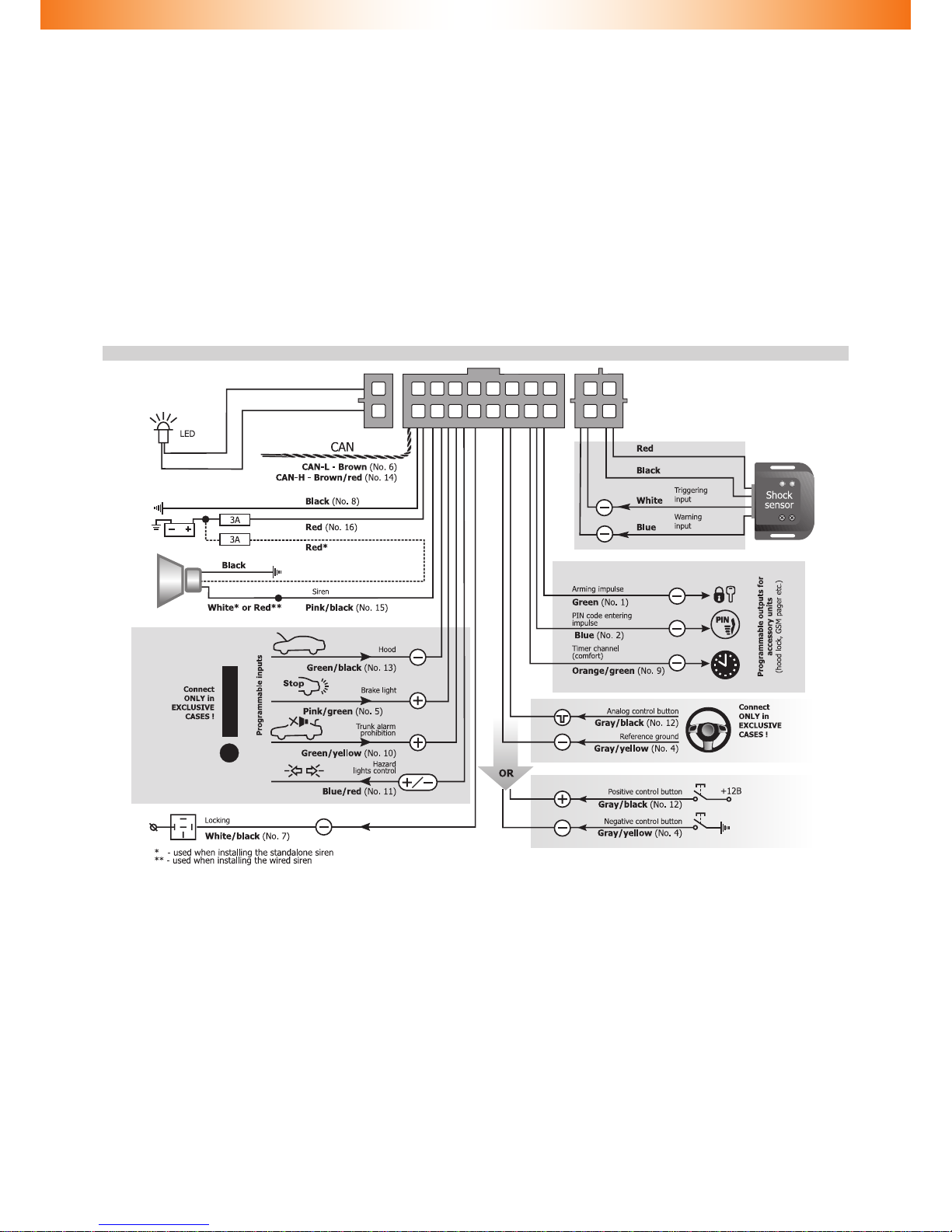
Alarm Inputs / Outputs
Alarm Inputs / Outputs functionalities are described in Tables 3, 4, 5, while contact numeration is indicated on g. 1. Input / Output congura-
tion is carried out via programming (see Alarm hardware features programming (Menu 1))�
Fig� 1� Port connector pins enumeration
from wiring viewpoint�
Table 3� Alarm main port description
No� Color Type Function Current, mA
1Green (-) Output Programmable negative output 150
2Blue (-) Output Programmable negative output 150
3- Not used - -
4Gray/Yellow Analog / digital button Reference ground / Negative button 0,5
5Pink/Green (+) Input Programmable positive input 1,5
6Brown CAN CAN-L
7White/Black (-) Output Engine locking 150
8Black Power supply Ground - 1)
9Orange/Green (-) Output Programmable negative output 150
10 Green/Yellow (+) Input Programmable positive input 1,5
11 Blue/Red (+/-) Output Alternate hazard lights control 150/150
12 Gray/Black Analog / digital button Analog button / Positive button 0,5
13 Green/Black (-) Input Programmable negative input 1,5
14 Brown/Red CAN CAN-H
15 Pink/Black (+/-) Output Siren control (+) / Horn control (-) 1300/150
16 Red Power supply +12 В 1500/2
2)
1) – Useful current of output No� 8 depends on demand connected to nega-
tive outputs�
2) – Typical useful current values in operation and idle modes are indicated
and may change depending on positive outputs demand�
Outputs No� 1, 2, 7, 9, 11, and 15 are protected from short circuit,
inductive eruptions, overheating and maximum demand surpass-
ing�
Alarm pin contacts description
Pins No� 1, 2, 9 “Programmable negative outputs”�
Pin No� 3� Is not used�
Pin No� 4� “Reference ground / Negative button”� Depending on con-
trol button type choice one of the following functions is used:
◊ Reference ground: when selecting the analog control button
it is connected to the corresponding vehicle wire (see Integra-
tor les).
◊ Negative button: is connected to negative (controlled by mak-
ing contact with the ground) button� It is used in case if there
are no original buttons perceived by the Alarm�
If the vehicle has original buttons controlled via CAN bus that
are perceived by the Alarm, this input may be unused�
Pins No� 5, 10� “Programmable positive inputs”�
Pins No� 6, 14 “CAN-L� CAN-H vehicle data bus” are connected to ve-
hicle CAN bus (see Integrator les)
Pin No� 7� “Engine locking”� Is connected to one of relay coil contacts
that is used for engine operation or launch blocking control� The output
can be set for controlling a normally open or normally closed relay�
Pin No� 8 “Ground” is connected to the vehicle’s body in one of the ar-
eas determined by vehicle manufacturer for connecting the ground
of original electric equipment�
Pin No� 11 (+ / -) output “Alternate hazard lights control” is used
for hazard lights control in vehicles where CAN bus control of hazard
lights is not available� For information on particularities of connection
to each given vehicle please refer to Integrator les�
Pin No� 12 “Analog button/Positive button”� Depending on control
button type choice one of the following functions is used
◊ Analog button is connected to the corresponding vehicle wire
at the steering wheel contact helix port (see Integrator les).
◊ Positive button is connected to the positive button (the
one controlled by +12V voltage)� It is used in case if there
are no original vehicle buttons perceived by the Immobilizer�
If the vehicle has original buttons controlled via CAN bus that
are perceived by the Immobilizer, this input may be discarded�
Pin No� 13 (-) programmable negative input�
Pin No� 15 Siren control / Horn control� The required algorithm
is set when installing the Alarm (see Alarm hardware features pro-
gramming (Menu 1))�
Pin No� 16� Alarm power supply is connected through 3 A fuse
to one of vehicle wires that has +12 V constant voltage�
Table 4� Sensors connection port description
No� Color Type Function
1Red Power supply +12V sensor power supply
2Black Power supply Sensor power supply ground
3White (-) Input Sensor 2 (Triggering)
4Blue (-) Input Sensor 1 (Warning)
Table 5� LED connection port description
No� Color Type Function
1Blue Power supply Ground
2Red Power supply +12V
6
External sensors connection
The shock sensor included in the delivery kit is equipped with dedi-
cated outputs for warning and alarm� This sensor operates correctly
in both multiplex and standard modes� Sensor connection is carried
out with a special harness supplied in the kit� No additional program-
ming is required�
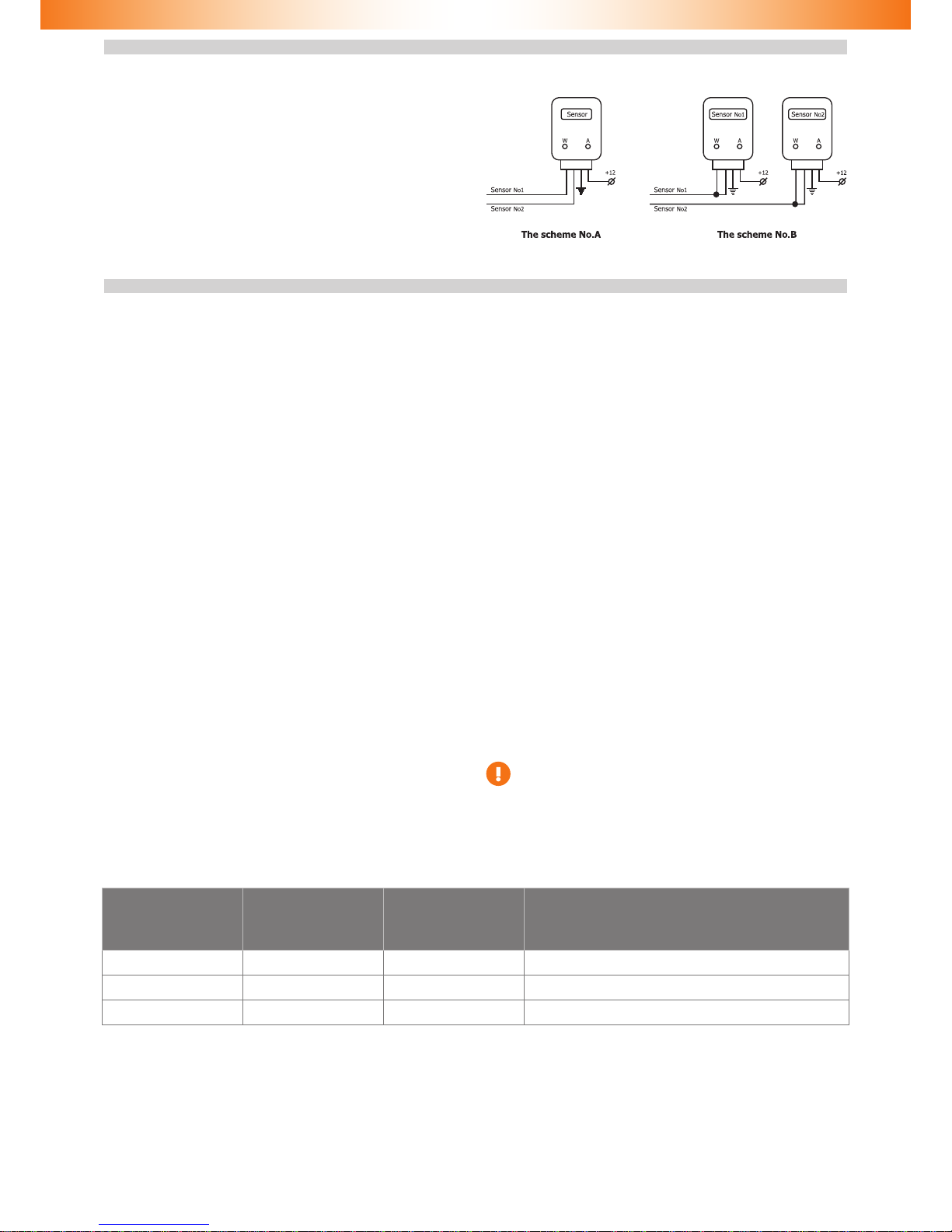
When it is necessary to install other sensors, various connection
schemes are available, two of which are presented below�
Should the sensor with dedicated warning and alarm zones please
refer to Scheme No� A� It is necessary to use the standard sensors op-
eration mode (see Alarm hardware features programming (Menu 1)
section)� In this scheme Sensor No� 1 has a functional purpose of
warning input, while Sensor No� 2 is the triggering input�
When connecting two multiplex sensors Scheme No� B is applied� In
this case it is necessary to program the multiplex sensors inputs oper-
ation (see Alarm hardware features programming (Menu 1) section)�
In this scheme functional purposes of sensor inputs are identical�
When receiving a signal longer than 0�8 sec, Warning is triggered� If
the signal is longer than 0�8 sec, Alarm is activated�
Alarm programming
Alarm programming is carried out with Programming button
Programming stage one. Alarm interfacing with the vehicle
Identifying the vehicle model
Vehicles supported by the Alarm are divided into functional groups,
each of which is divided into subgroups� All groups and subgroups
are assigned with item ordinals (see Integrator les). Interfacing
is the procedure of Alarm detecting vehicle group and subgroup�
There are two interfacing options:
1 Automatic interfacing
In order to automatically interface the Alarm with the vehicle it is
necessary to carry out a set of actions (see Integrator les). Upon
vehicle identication algorithm is launched the Alarm emits a con-
stant audible signal�
If the Alarm identies only the vehicle group, then it will stop emit-
ting the constant signal and will periodically emit series of audible
and light signals, where the number of signals will correspond with
the group number�
If the Alarm identies both the group and subgroup of the vehicle,
then it will inform on the completion of vehicle interfacing with an
audible sound trill and will emit three series of audible and light sig-
nals where the number of long signals corresponds with the group
number and the number of short signals corresponds with the sub-
group number�
2 Forced interfacing
This algorithm is used in extraordinary cases�
Programming is carried out with the integrated Programming but-
ton� Prior to interfacing procedure initiation vehicle group must not
be identied and CAN bus must not be connected. Programming will
stop if Programming button shall not be pressed within 60 seconds�
Programming sequence:
2�1 Power the Alarm and wait for discontinuous audible and
light signal�
2�2 Enter Menu 1 by pressing and releasing the Programming
button 10 times (this needs to be done no later than 10
seconds after the system has been powered)� If the proce-
dure is carried out correctly, the Alarm will inform on this
fact with three audible and light signals�
2�3 Enter menu option No� 1 – Vehicle model – by pressing the
Programming button once� The Alarm will inform on option
condition with 1 audible and 1 light signal series�
2�4 Enter the vehicle’s group number by pressing the Program-
ming button for the corresponding number of times (see
Integrator les). The Alarm will periodically emit series of
audible and light signals where the number of signals cor-
responds with the group number�
2�5 Enter the vehicle’s subgroup number by pressing the Pro-
gramming button for the corresponding number of times
(see Integrator les).
Verify that the vehicle model has been chosen correctly with help
of audible and light signals (group number – pause, subgroup num-
ber – pause):
◊ If the vehicle model has been chosen correctly, press the Pro-
gramming button once� Audible and light signals will stop and
the vehicle model will be programmed�
◊ If the vehicle model has been chose incorrectly, then press the
Programming button twice� Repeat the programming proce-
dure beginning from p� 2�4�
Analog steering wheel buttons programming
In order to use the analog steering wheel buttons please do as
follows:
◊ • Right after the Immobilizer identies the vehicle model,
turn the ignition on and wait for no less than 5 seconds�
◊ • Press all the steering wheel and steering wheel column
joysticks’ buttons (cruise control, central unit control etc�) se-
quentially (one after another)� The buttons, upon pressing of
which and audible signal will be heard and a light signal will be
seen, are available for use�
◊ • Turn the ignition off; an audible sound trill will be played.
◊ • Turn the ignition on.
◊ • Assign the Programming button from available ones by
pressing and holding it for no less than 5 seconds (until an
audible signal will be heard)�
It is necessary to initiate steering wheel analog button within
15 minutes since the Alarm interfacing with the vehicle� If
more than 15 minutes has passed please revert the settings
back to factory default and reprogram the Alarm�
Programming stage two. Alarm conguration programming
At stage two Alarm hardware functions and user settings are changed and a new PIN code is programmed� Three independent menus are
used during programming (see Programming menu table)�
Table 6� Programming menu
Name Menu entering code Audible signals number Function
Menu 1 10 3 Alarm hardware settings conguration
Menu 2 12 4 Alarm user settings conguration
Menu 3 14 1 PIN code changing

7
Alarm hardware features programming (Menu 1)
Programming is carried out in accordance with Immobilizer hardware features programming (Menu 1) table�
Table 7� Alarm hardware features programming (Menu 1)
No� Option name Setting
range Factory default settings Notes
1 Vehicle model – – –
2 Engine locking 1—4 2
1- normally open relay control
2- normally closed relay control
3- reserved by manufacturer
4- starter locking (normally closed relay control)
3—— — —
4External buttons type 1—2 – 1- Outputs No� 4 and 12 are used as analog buttons
2- Output No� 4 and 12 are used as digital buttons
5 Hazard lights control algorithm 1—5 –
1- impulse negative control
2- status negative control
3- impulse positive control
4- status positive control
5- lamps control
6 Siren control / Horn control 1—2 1
Output No� 15 operation mode and polarity selection�
1 – Siren control� Constant level signal is formed (+12V)�
2- Horn control� Dashed negative signal is formed� Used for origi-
nal vehicle horn control�
7Timer channel (comfort) feature
running time 1—6 3 One unit is 10 seconds
8External sensors operation
mode 1—2 2 1 – multiplex external sensors operation mode
2 – standard external sensors operation mode
9 (-) output No� 1 1—24 2
Arming impulse
Programmable output (see Programmable outputs functions
table)
10 (-) output No� 2 1—24
4
PIN code entering
impulse
Programmable output (see Programmable outputs functions
table)
11
(-) output No� 9
1—24
23
Comfort timer
channel
Programmable output (see Programmable outputs functions table)
12 (+) input No� 5 1—7
1
Brake lights
condition control
Programmable input (see Programmable outputs inputs table)
13 (+) input No� 10 1—7
7
Trunk alert
prohibition
Programmable input (see Programmable outputs inputs table)
14 (-) input No� 13 1—7 2
Hood control Programmable input (see Programmable outputs inputs table)
15 – – – –
16 Speed control 1-2 1 1-enabled
2-disabled
17 Brake pedal pressings number 1-7 3 –
Annotations to Table
p� 1 Vehicle model allows forced selection of vehicle group and sub-
group�
p� 2 Engine locking has four conditions
1 Output No� 7 is set for controlling the normally open relay�
2 Output No� 7 is set for controlling the normally closed relay�
3 Reserved by manufacturer�
4 Starter locking (normally closed relay control)� A constant level signal
is formed with active bus prior to PIN code entering, which allows
locking the starter�
p� 4 External buttons type� Depending on the buttons used
◊ Inputs No� 4, 12 are used for connecting analog (steering
wheel) buttons
◊ Inputs No� 4, 12 are used for connecting digital (positive/nega-
tive) buttons
This option can be changed only with built-in Programming unit
prior to the rst entering of PIN code with analog or digital buttons.
For changing the option condition again, please revert to factory
original settings�
8
Alarm connection diagram (original settings)
(see
Integrator les)
(see
Integrator les)
p� 5 Hazard lights control algorithm allows setting the required con-
trol algorithm� In the majority of cases the algorithm is set automati-
cally during vehicle interfacing�
p� 6 Siren control / Horn control� Allows setting output No� 15
for emitting the Alarm signal to the vehicle’s original horn�
p� 7� Timer channel (comfort) feature running time� Allows setting
the time within which Timer channel (comfort) feature will be active�
Time is set in 10 sec intervals, i�e� if the option’s setting is 3, and then
the feature will be active for 30 sec�
p� 8� External sensors operation mode� Allows setting one of two ex-
ternal sensors operation nodes (see External sensors connection sec-
tion)�
1 Multiplex mode for connecting multiplex sensors
2 Standard mode for connecting sensors with dedicated warning
and alarm outputs�
p� 9, 10, 11� Programmable outputs� Are designed for forming
the Alarm outputs conguration that differs from the original one by as-
signing each of the outputs with one of 24 features from Alarm pro-
grammable outputs features table�
p� 12, 13, 14� Programmable inputs� Are designed for forming
the Alarm inputs conguration that differs from the original one by as-
signing each of the inputs with one of 7 features from Alarm program-
mable inputs features table�
p� 16� Speed control� Allows setting Immobilizer and Anti HiJack
algorithms for locking triggering�
p� 17� Number of brake pedal pressings� Allows setting a number of
brake pedal pressings which is necessary for triggering Anti HiJack
function� If the Speed control is on, the setting of p� 4 does not affect
anything�
9
Table 8� Programmable Alarm outputs functions
Function Function description
No Name
1Security Constant level signal is formed while the Alarm is in Security mode
2Arming impulse
0�8 second long impulse is formed when Alarm is entering the Security mode, an impulse is also formed when
Anti HiJack feature is triggered�
3Disarming impulse
0�8 second long impulse is formed when Immobilizer is leaving the Security mode
4PIN code entering impulse
0�8 second long impulse is formed when the correct PIN code is entered� The impulse is also formed
in Maintenance mode 1 second after the ignition has been turned on even if the PIN code had not been
entered�
5Original alarm system
panic
Constant level signal is formed while the original vehicle alarm (if the vehicle is equipped with it) is in
Alarm condition�
6Siren panic
30 seconds long constant level signal is formed if one of the following zones is triggered while the vehicle
is in Security condition: doors, hood or trunk opening� The function can be applied in vehicles that are not
equipped with original alarm system� The signal stops when vehicle is not in Security mode any longer�
7Horn panic
30 seconds long constant level signal is formed if one of the following zones is triggered: doors, hood
or trunk opening� The function can be applied in vehicles that are not equipped with original alarm system�
The signal stops when vehicle is not in Security mode any longer� This feature is used for sending an alarm
signal to the original vehicle horn�
8Doors, hood and trunk
Constant level signal is formed if one of preset doors, hood or trunk is opened�
9Sensors ignoring
Constant level signal is formed when the trunk is open in Security mode if the trunk has been opened with
the original remote control� Also the signal is formed for the purposes of Comfort feature� The feature’s
purpose is to deactivate the sensors in order to prevent false alarms�
10 Original buttons
Constant level signal is formed if the preset vehicle button is pressed�
11 Ignition
Constant level signal is formed when ignition is turned on (including engine starting)�
12 ACC
Constant level signal is formed when vehicle ACC are on (1st key position, may match with ignition on cer-
tain vehicles)� It is turned off only when the ignition key is out of ignition lock� Can be used for correct
accessory alarm system or multimedia system power management�
13 Engine on
Constant level signal is formed when the engine is on�
14 Engine rpm
Impulse signal is formed� Its impulse sequence frequency is proportional to the engine crankshaft rotation
frequency� 1 impulse per second corresponds with 20 crankshaft rpm� The signal’s purpose is to determine
the approximate and not precise rpm value�
15 Transmission condition
Constant level signal is formed if transmission handle is set in preliminarily programmed position (P, R, N,
and D
1)
)� For robotized transmission the positions are R, N, D
1)
; for manual transmission only R position
is available�
16 Vehicle is moving
Constant level signal is formed if the vehicle speed has exceeded a certain threshold value (depends
on vehicle and varies in the range of 5 to 10 km/h)�
17 Front parking sensors
activation
Constant level signal is formed if the engine is on and the transmission is in D
1)
position or R position
(for mechanical transmission only R position is available) and the movement speed is less than 15 km/h
18 Rear parking sensors
activation
Constant level signal is formed if the engine is on and the transmission is in R position and the vehicle move-
ment speed is less than 15 km/h�
19 Movement speed
Impulse signal is formed� Its impulse sequence frequency is proportional to the vehicle speed� 1 impulse
per second corresponds with 1 km/h speed� The signal’s purpose is to determine the approximate and not
precise speed value�
20 Brake
Constant level signal is formed when the brake pedal is pressed�
21 Hand brake Constant level signal is formed when the vehicle is on hand brake�
22 External lights Constant level signal is formed when the external lights are on�
23 Timer channel (Comfort) Constant level signal is formed for a set period of time (10 to 60 seconds) upon arming� The time is set in
10-second intervals�
24 Starter and diagnostics
bus locking
Constant level signal is formed with the bus active prior to PIN code entry� The signal is also formed if Anti
HiJack feature has been triggered�
1) all handle positions for vehicle advancement (D, S, M, L etc�)�

10
Table 9� Programmable Alarm inputs functions
Function Function description
No Name
1Brake lights condition
control
The function is used only in case if the vehicle’s CAN bus does not contain data on brake pedal position� In this
case Brake lights condition control input is to be connected to brake pedal terminal switch output�
2Hood control
The function is used in case if vehicle’s CAN bus does not contain data on hood position� In this case Hood
control input is to be connected to hood’s terminal switch�
3Doors control
The function is used in exceptional cases when CAN bus does not contain data on doors position (see
Integrator les).
4Central locking system
is closed (status)
The function is used in exceptional cases when CAN bus does not contain data on central locking system
status (see Integrator les).
5Central locking system
is open (status)
The function is used in exceptional cases when CAN bus does not contain data on central locking system
status (see Integrator les).
6Ignition control
The function is used only in cases when getting the correct data from CAN bus is not available� This situ-
ation may occur when certain vehicle circuits are blocked� In this case Ignition control input is to be con-
nected to the vehicle wire that has a constant level signal when the ignition is on�
Connecting this input does not cancel ignition analysis via CAN bus� Ignition is considered as turned
on when data is received by any informational channel (CAN bus or analog input)�
7Trunk alarm prohibition
The function is used in case if the alarm is triggered when the trunk is opened via the original remote
control and/or keyless access system�
In this case Trunk alarm prohibition input is to be connected to trunk opening feed control wire�
Input control is carried out only in Security mode� When a command to open the trunk is detected,
the alarm ignores external sensors inputs and trunk terminal switch for 5 seconds until the actual opening
of the trunk� In 5 seconds after the trunk lid has been closed, sensors inputs and the trunk will be secured
Programming sequence
1 Turn the ignition on�
2 Enter the PIN code and wait for conrmation.
3 Enter Menu 3 by pressing and releasing the Programming but-
ton 10 times (you need to do this no later than 10 seconds
upon PIN code entering)� The Alarm will notify of menu ac-
cessed by three audible and three light signals�
4 Select menu option by pressing and releasing the Programming
button for the number of times corresponding with the menu
option number� The Alarm will inform on menu number by se-
ries of audible and light signals�
5 Go to option setting by pressing and holding the brake pedal�
The Alarm will inform you on the option setting by series of au-
dible and light signals, and their duration will change�
6 Change the option setting by pressing and releasing the Pro-
gramming button for the number of times necessary for mov-
ing from the current setting number to the required setting
number in the option (e�g�, in order to change function No�
2 (Arming impulse) with function No� 16 (Vehicle is moving)
you need to press and release the Programming button 14
times� The Alarm will inform on the new option setting with
series of audible and light signals� It is necessary to consider
that during navigation in the option the rst number goes after
the last one� Release the brake pedal; the Alarm will indicate
the current setting and then the current menu option num-
ber� Now you can proceed with programming the next option
and leave the programming mode�
6�1� Function No� 8 Doors, hood and trunk programming algorithm
(applicable only for options No� 10, 11 and 12 of Menu 1)�
6�1�1 Set any combination of doors, hood and trunk, the opening
of which will cause the Alarm to form a signal on the program-
mable output� For the purposes of this description doors, hood
and trunk are referred to as doors�
6�1�2 With the brake pedal pressed go to option number 8 set-
tings� The Alarm will inform on option condition twice with
series of 8 audible and light signals, after which it will start
emitting irregular audible and light signals� When the irregu-
lar signals are activated, release the brake pedal� The Alarm
will continue emitting irregular signals� Open the doors that
are to be identied on this output, the rest are to be closed
(you can open the doors in advance)� Press the brake pedal
again� The Alarm will inform on option setting change with
series of 8 signals and the doors will be assigned to this output�
If the brake pedal is not pressed and current option program-
ming is left, the Alarm will save its previous condition� Release
the brake pedal and the Alarm will go to option number indica-
tion�
6�2� Function No� 10 Original buttons programming algorithm (ap-
plicable only for options No� 10 11 and 12 of Menu 1)�
6�2�1 With the brake pedal pressed go to option number 10 set-
tings� The Alarm will inform on option condition twice with se-
ries of 10 audible and light signals, after which it will start emit-
ting irregular signals� When the irregular signals are detected,
press the required button while holding the brake pedal (for
the list of buttons of the given model, please see Integrator
les). If the Alarm has perceived the button, it will stop emit-
ting irregular signals and will start indicating the option setting
number with series of 10 audible and light signals� Release
the brake pedal, the Alarm will indicate menu option number�
If the brake pedal is released prior to the button is pressed,
the Alarm will save its previous condition and will start indicat-
ing the menu option number�
6�3� Function No� 15 Transmission condition programming algo-
rithm (applicable only for options No� 10, 11 and 12 of Menu
1)�
6�3�1 With the brake pedal pressed go to option number 15 set-
tings� The Alarm will inform on option condition twice with
series of 15 audible and light signals, after which it will start
emitting irregular signals� When the irregular signals are de-
tected, change the transmission to the required position: P,
N, D*or R (transmission handle can be set in the necessary
position in advance); for robotized transmission the positions
are R, N, D*; for manual transmission only R position is avail-
able� Release and press the brake pedal again� The Alarm will
stop emitting irregular signals and will start indicating the op-
tion setting number with series of 15 audible and light signals�
Release the brake pedal, the Alarm will indicate menu option
number� If the brake pedal is released prior to the button
is pressed, the Alarm will save its previous condition�
7 In order to go to next menu option programming press and re-
lease the Programming button for the number of times nec-
essary for navigation from the required option (e�g�, in order
to navigate from option No� 2 to option No� 8 in Menu 1 press
and release the Programming button 6 times)� Important note:
when navigating menu options, the rst option follows the last
one�
Exiting the programming mode� The Alarm will exit programming
mode and save all conguration settings in energy independent
memory when ignition is turned off or within 60 seconds after last
menu action if the brake pedal is released�
* all handle positions for vehicle advancement (D, S, M, L etc�)�

11
Alarm user settings programming (Menu 2)
Programming is carried out in accordance with table Alarm user settings conguring (Menu 2)
Table 10� Alarm user settings conguration (Menu 2)
No.
Description
Current option setting*
Factory
default
settings
On Off
Range
LED Qty.
of audible
signals LED Qty. of audible
signals
1 Immobilizer feature On On 1 Off 2 -
2 Anti HiJack feature On On 1 Off 2 -
3 Anti HiJack feature response delay 1 - - - - From 1 to 10*
4 Siren working modes 4 - - - - From 1 to 4*
5PIN code entering audio conrmation On On 1 Off 2 -
6 Maintenance mode audio indication On On 1 Off 2 -
7Central locking system activation when driving Off On 1 Off 2 -
8Central locking system deactivation when igni-
tion is turned off Off On 1 Off 2 -
9 Comfort feature control On On 1 Off 2 -
10 Arming / disarming audible conrmation volume 4 - - - - From 1 to 4*
* – number of audio signals is indicated�
Annotations to Table
p� 1 “Immobilizer feature” allows turning the Immobilizer feature
on or off�
p� 2 “Anti HiJack feature” allows turning the Anti HiJack feature on or
off�
p� 3 “Anti HiJack feature response delay” allows setting the distance
before locking (Speed control is on) or time before locking (Speed con-
trol is off)� The time is set by 20 second intervals; the distance is set by
100 meter sections� For example, if the option’s setting is 3, then:
◊ Locking activation delay is 60 seconds;
◊ Distance before locking is 300 meters�
p� 4 “Siren working modes”� Allows setting the siren working mode:
1 —Siren is disabled;
2 —Siren is not triggered in warning mode;
3 —Volume level of warning signals corresponds to the volume
level when arming/disarming (see� p�10);
4 —Siren is enabled (maximum volume level)�
p� 5 “PIN code entering audio conrmation” allows turning PIN code
entering audio conrmation on or off.
p� 6 “Maintenance mode audio indication” allows turning Mainte-
nance mode audio indication on or off�
p� 7 “Central locking system activation when driving” allows turning
the automatic central locking when driving feature on or off�
p� 8 “Central locking system deactivation when ignition is turned off”
allows turning the automatic central lock unlocking upon ignition fea-
ture deactivation on or off�
p� 9 “Comfort feature control” allows turning automatic windows
closing during vehicle locking on or off�
p� 10 “Arming / disarming audible conrmation” allows setting an
arming / disarming audible conrmation volume level:
1 —silent arming/disarming
2 —minimum volume level
3 —medium volume level
4 —maximum volume level�
Programming sequence
1 Turn the ignition on
2 Enter the PIN code and wait for conrmation (see PIN code
entering section)
3 Enter Menu 2 by pressing and releasing the Programming but-
ton 12 times (start doing this no later than 10 seconds upon
PIN code entering)� If all operations have been carried out cor-
rectly, the Alarm will inform on this fact by 4 audible signals
(see Programming menu table)�
4 Beginning from point 4, programming algorithm is analogical
with the one described in Alarm hardware features congura-
tion (Menu 1), except for points 6�1, 6�2, 6�3�
PIN code changing
1 Turn the ignition on
2 Enter the PIN code
3 Press the Programming button 14 times� Wait for Alarm’s con-
rmation by 1 audible and 1 light signals.
4 Set the new PIN code by using any combination of buttons
perceived by the Alarm (see Integrator les). When entering
a new PIN code, each pressing perceived by the Alarm is con-
rmed by the audible and light signals for further controlling
assistance�
5 Wait for conrmation by 1 audible and 1 light signal.
6 Re-enter the new PIN code�
7 Wait for conrmation:
◊ 2 audible and light signals and a sound trill mean that the PIN
code has been changed and the Alarm has left the PIN code
changing mode�
◊ Sound alert means that the PIN code has not been changed
and the Alarm has left the PIN code changing mode� A mistake
has been made when entering the new PIN code conrmation
and it is necessary to repeat the PIN code changing procedure
starting from p� 1�
You can exit the PIN code changing mode anytime by turning the ig-
nition off�
Programming button changing
1 Reset all settings to factory default�
2 Interface the Alarm with the vehicle�
3 If analog steering wheel buttons are used please dene them
(see above for the description of this procedure)�
4 In order to assign any of the buttons perceived by the Alarm
as the Programming button, press the selected button and hold
it for longer than 5 seconds until a long audible signal will
be heard�
Programming button can be assigned within 15 minutes after
Integrator les interfacing with the vehicle.
12
Programming examples
Example 1
Objective: You would like to change the factory settings of the Alarm:
set output No� 2 Engine locking to control the normally open relay�
Execution:
◊ Turn the ignition on�
◊ Enter the PIN code and wait for confirmation�
◊ Enter Menu 1 by pressing and releasing the Programming
button 10 times� If you have performed all the actions cor-
rectly, the Alarm will notify you of it with 3 audible and
light signals�
◊ According to Alarm hardware functions configuring
(Menu 1) option No� 2 Engine locking is to be selected� To
do so, press and release the Programming button 2 times�
The Alarm will inform you on the selected menu option
number by series of 2 audible and light signals�
◊ Enter option No� 2 by pressing and holding the brake pedal�
The Alarm will inform you on the option setting by repeated
double audible and light signals because the current (fac-
tory set) option setting is normally closed relay control�
◊ Select the normally open relay control by pressing and re-
leasing the Programming button 3 times, for the second
setting is followed by the third� The Alarm will inform you
on the option setting with series of 1 audible signal�
◊ Exit programming mode by turning the ignition off�
Example 2
Objective: You would like to change the factory settings of the Alarm:
to increase the Anti HiJack activation distance from 100 to 300 meters�
Execution:
◊ Turn the ignition on�
◊ Enter the PIN code and wait for confirmation�
◊ Enter the Alarm setting mode by pressing and releasing
the Programming button 12 times (start doing it no longer
than 10 seconds after entering the PIN code)� If you have
performed all the actions correctly, the Alarm will notify
you of it with 4 audible and light signals�
◊ Select the programming option for setting the Anti HiJack
activation distance� According to Alarm user settings con-
figuration (Menu 2) table, option No� 5 is to be selected� To
do so, press and release the Programming button 5 times�
The Alarm will inform you on the selected menu option
number by series of 5 audible and light signals�
◊ Enter option No� 5 by pressing and holding the brake pedal�
The Alarm will inform you on the option setting by repeated
single audible and light signals because the current (fac-
tory set) option setting is 1 (which stands for 100 meters
distance)�
◊ Change option No� 5 setting by pressing and releasing the
Programming button twice, therefore increasing the option
setting by 2 (1+2=3)� The Alarm will inform you on the op-
tion setting with series of 3 audible and light signals (300
meters)�
◊ Exit the setting mode by turning the ignition off�
Resetting to factory default settings
The Alarm has a procedure of resetting the programmable settings,
where all vehicle model settings are removed from Alarm’s permanent
memory while PIN code and all other programming options are re-
turned to factory original val-
ues�
If certain or all menu op-
tions are password protected
(see Alarm hardware settings
programming (Menu 1), p�
2), only the options that are
not prohibited will be reset�
The remaining ones will keep
their current values�
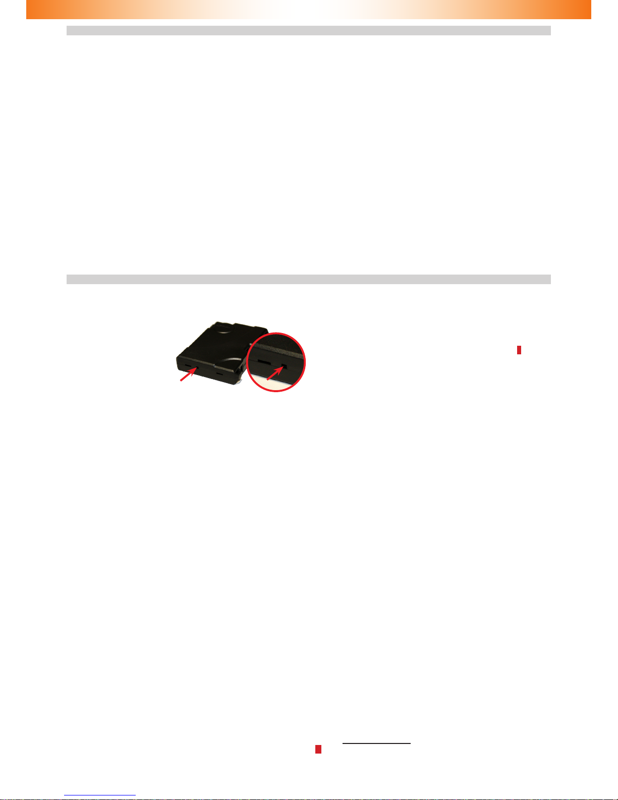
In order to reset to factory default:
1 Remove power supply from the Alarm
2 Press and hold the integrated Programming button (see Fig� 2)
3 Connect the power supply while holding the button� The Alarm
will emit dashed audible signal�
4 Release the button and wait until the dashed signal stops�
5 Turn the ignition on and enter the current PIN code *�
6 An audible trill will be heard, which indicates that resetting to
factory default has been completed�
7 Remove the power supply and disconnect the Alarm from CAN
bus�
* If the Alarm is not installed in the vehicle, please enter the PUK code with
the integrated button�
Fig� 2� Integrated button
13
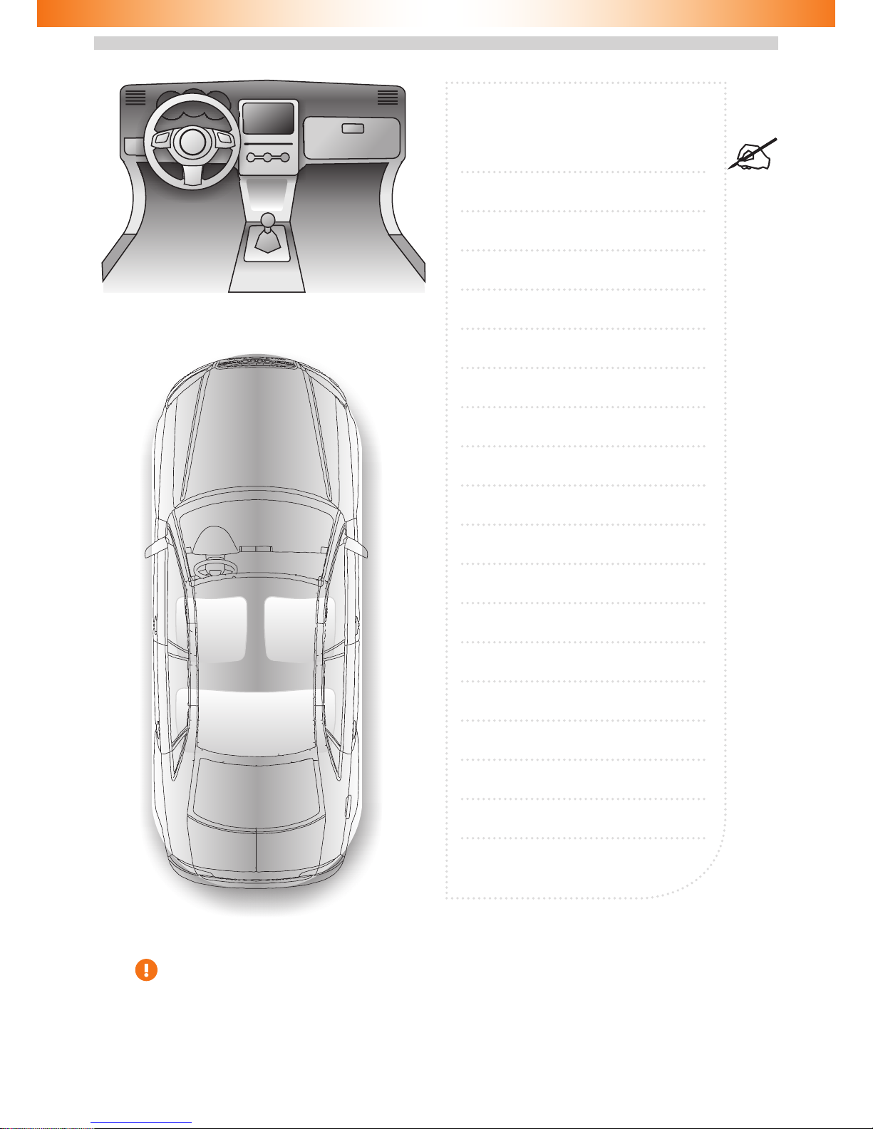
Installation scheme form
Keep the lled up scheme in the place which is unavailable for unauthorized persons.
Mark car alarm element locations on the scheme� It will
help to nd them if required.
14
Standard delivery kit
Item Quantity, pcs
Central unit 1
Main wire harness 1
LED indicator with wiring 1
Shock sensor 1
Wire hardness for shock sensor connection 1
Siren 1
CD 1
Reminder card 1
User manual 1
Warranty certicate 1
Connection diagram 1
Packaging 1
Technical data and operation conditions
Parameter Value
Power supply voltage, V 9 … 15
Maximum current drain in standby mode, mA 1,5
Maximum current drain in operation mode, A 1,5
Operating temperature °C – 40 … + 85
Storage temperature °C – 40 … + 85
Maximum relative air humidity, % 95
Manufactured by TEC Electronics Ltd�
The product is manufactured in accordance with TC 4372-004-78025716-09�
Certicate of conformity No. POCC RU. AB75. B00132
The product corresponds with the requirements of the following regulations:
GOST R 41�97-99, GOST R 50789-95

This manual suits for next models
1
Table of contents
Other TEC Electronics Car Alarm manuals


Popular Car Alarm manuals by other brands

Prestige
Prestige APS 33 owner's manual

Connect2Car
Connect2Car MFC-F installation manual

Autobahn
Autobahn Security System owner's manual

Renault
Renault 7877 user manual

Federal Signal Corporation
Federal Signal Corporation Pathfinder Siren Series Installation and maintenance manual

Freedom
Freedom 650 quick start guide

Magnadyne
Magnadyne PL30 owner's manual

Scytek electronic
Scytek electronic ASTRA 777-TC product manual

Avital
Avital AviStart 6500 owner's manual

Python
Python 4106P owner's guide

CrimeStopper
CrimeStopper CS-2011RS Series III Super Rage Operation instructions

Scytek electronic
Scytek electronic ASTRA 70000000 product manual


