Tec-Innovation InnoMake v.1 User manual
User manual
Version: 03 / 2021

TDIM1_4_User Manual_1 2
Table of Contents
1. Introduction..................................................................................4
1.1. Trade name and identification .........................................................4
1.2. Explanation of symbols....................................................................5
2. Product description.....................................................................6
2.1. Getting to know the product components.........................................7
2.2. Control elements and interfaces....................................................10
2.3. Product variants and shoe models.................................................11
2.4. Accessory: InnoMake App.............................................................12
3. Purpose and function................................................................13
3.1. Intended users...............................................................................14
3.2. Area of application and environmental conditions..........................15
4. Application .................................................................................16
4.1. Switching on / off and operational state.........................................16
4.2. Charging the battery......................................................................17
4.3. Checking the battery charge level .................................................18
4.4. Prepare shoes and attachment parts.............................................19
4.5. Your first steps ..............................................................................20
4.6. Changing the measurement range ................................................20
4.7. Activate intelligent mode................................................................22
4.8. Activate LED .................................................................................22
4.9. After use........................................................................................23
4.10. Attachment part warning tones......................................................24
4.11. Overview of InnoMake signals.......................................................25
5. Safety instructions.....................................................................26
5.1. Information and measures in case of product (mal)functions.........27

TDIM1_4_User Manual_1 3
5.2. Information and measures in case of environmental influences.....29
6. Handling .....................................................................................31
6.1. Storage and transportation............................................................31
6.2. Cleaning and disposal...................................................................32
7. Technical data............................................................................33
8. Legal information.......................................................................35
9. Closing remarks.........................................................................36

TDIM1_4_User Manual_1 4
1. Introduction
We at Tec-Innovation GmbH are happy that you have chosen our InnoMake
product. InnoMake is an intelligent obstacle detection system with which we
want to provide greater walking safety and reduce barriers in the interaction
with our environment.
For the unrestricted and safe use of InnoMake, it is important that you
carefully read through this entire user manual and also follow the safety
instructions.
The aim of this user manual is to help you get to know the InnoMake product
and facilitate your first steps with the product.
Reading the user manual will help you to understand and use the full
functionality of InnoMake. Keep this document so that you can refer to it and
read up on product details in the future.
You can also have this user manual read aloud at any time with the aid of a
reading programme on our website www.tec-innovation.com.
1.1. Trade name and identification
InnoMake
Serial number Attachment part 1: __________________
Serial number Attachment part 2: __________________
Tec-Innovation GmbH
LAB: Zachgasse 1
1220 Vienna
AUSTRIA
EMAIL: office@tec-innovation.com
WEB: www.tec-innovation.com

TDIM1_4_User Manual_1 5
1.2. Explanation of symbols
An understanding of the following symbols in the table below are important
and helpful for this user manual and the labelling on the product.
Symbol
Description
The symbol of an open book with the letter “i”for
“Information”is our request to please observe and
carefully read the user manual.
The legal manufacturer of your InnoMake and their
postal address is noted next to the symbol of a factory.
Declaration of conformity in accordance with the
applicable European guidelines
IP57
Protection rating against foreign objects and water:
5 = protected against dust
7 = protected against temporary submersion
SN
The letters “SN” describe the serial number of the
attachment part.
The symbol of a crossed-out wheelie bin concerns
products, such as InnoMake I, that contain batteries and
therefore must not be disposed of in normal household
waste.
Yellow framed text boxes with the lettering “NOTE”
contain important notes regarding your use of InnoMake.
Yellow framed exclamation marks highlight the relevance
of the information following the symbol.

TDIM1_4_User Manual_1 6
2. Product description
The InnoMake delivery includes:
▪two attachment parts with ultrasonic sensors
▪one battery charger with micro-USB connector
▪Spacer
▪User manual
▪Braille flyer
A pair of shoes with built-in metal tracks is also included in the product
scope, depending on your order. You will receive your shoes for InnoMake
separately, they are not included in this package.
If you use a pair of shoes of your choice, tracks for adaption to InnoMake
have been shipped to an orthopaedic shoe technician in your area.
You can also use the InnoMake App as an accessory for your InnoMake to
adjust the obstacle detection feedback to your preferences. The InnoMake
App is available in the App Store for iPhones. The InnoMake App is not
absolutely necessary for using InnoMake.
Information on the InnoMake App can be found in section 2.4 and in more
detail in the App user manual and the QuickGuide on the InnoMake App.
You can have the App user manual and this user manual read aloud with the
aid of a reading programme on our website www.tec-innovation.com. If
required, we will also send you the App user manual in paper form to your
door free of charge. Please contact us if you would prefer this option.

TDIM1_4_User Manual_1 7
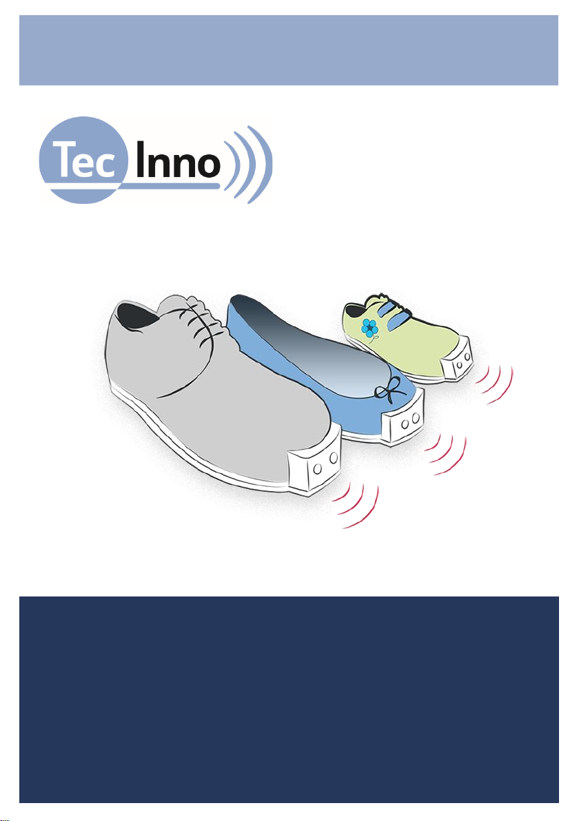
The above-mentioned product components are shown in connection with
each other in the drawing below.
The drawing shows a shoe with a narrow midsole, the concealed
compartment at the front of the shoe and the underlying profiled sole. An
attachment part with the processing unit is shown in front of the shoe. The
attachment part contains the two ultrasonic sensors facing forward and away
from the shoe for obstacle detection in the walking direction. Radio waves
between the attachment part and a smartphone present the possible use of
the InnoMake App, which can be connected to the shoe via Bluetooth®.
2.1. Getting to know the product components
You can get to know your InnoMake below together with this user manual.
Make sure that you have your corresponding shoes at hand and take the two
attachment parts out of the packaging. Read the following description
carefully to explore the product components.

TDIM1_4_User Manual_1 8
Shoes with built-in metal tracks
If you hold one of the two shoes in your hand, you can feel the compartment
for the attachment parts in front, at the front of the shoe. This compartment is
integrated in the shoe midsole and results from an integrated metal track and
gap above. The metal track protects the attachment part of your InnoMake
during use. By adapting the shoe to InnoMake, the front of the shoe becomes
a little longer because the metal track protrudes about 22 mm to
accommodate the attachment parts. The compartment is protected from the
ground by a profiled sole.
When InnoMake is in use, you will feel vibrational feedback of obstacle
detection in the front area of the shoes equipped with the attachment parts.
We tell you the distance to an object in your walking direction via the
frequency of the vibration.
Information on the intended use and function will follow in section 3.
Attachment parts with ultrasonic sensors
Hold one of the two attachment parts in your hands. The units are completely
identical, so it does not matter which one you examine more closely. The
attachment parts have an L-shaped design, whereby a wider and bulkier part
meets a flatter, thinner part at a right angle. The wider part contains the
sensor system in your InnoMake, we call it the attachment. The thinner part
is intended for insertion into your shoe compartment. The attachment part is
inserted into the shoe in such a way that the attachment at the front of the
shoe points upwards.
We will concentrate on the attachment in the following section. We designate
the attachment surface where you can feel two notches as the ‘front side’for
joint orientation. The opposite attachment surface enclosed by the right angle
is the ‘back side’. The front side faces the walking direction during use and it
is also recognisable by the fact that our company logo (a dot with three
waves) is embossed in the area below the notches.

TDIM1_4_User Manual_1 9
Sensors are installed in the two notches on the front side. These two sensors
send and receive ultrasonic waves while your InnoMake is switched on.
When your InnoMake is in use, the ultrasonic sensors point in your walking
direction and detect obstacles in front of you.
An LED is integrated in the middle between the ultrasonic sensors. This can
be activated on the attachment part and it improves your visibility, especially
in the dark.
Activation of the LED is described in section 4.8.
Viewed from the front, there is a push button on the left side surface of the
attachment. If you press this button, the built-in micro-USB socket cover will
lift up on the opposite right side surface. You can only push the cover out of
its fixing by pressing the push button. You can rotate the cover to the side
and thus free the micro-USB socket in this pushed out state. The micro-USB
socket for the insertion of a micro-USB connector is intended for charging the
InnoMake together with the battery charger supplied by us.
Charging the InnoMake is described in section 4.2.
Three raised waves can be felt in the lower area on both side surfaces, i.e.
below the USB socket and below the side push button. These waves make it
easier to insert/remove the attachment part in/from the compartment. They
give you more grip, especially when removing an attachment part. In order to
avoid breaking the casing, do not pull the attachment part out with a grip on
the top edge of the attachment.
Turn the attachment part by 180° and inspect the back side of the
attachment. There is a push button in the top left corner of the back side,
which you can use to switch your InnoMake on and off and control further
functions.
The push button as a control element is described in more detail in section
2.2.

TDIM1_4_User Manual_1 10
An LED is installed on the left next to the push button, which provides you
with colour feedback on the battery status when the battery is charging. Of
course, InnoMake also provides you with acoustic information on the battery
charge level. Refer to section 4.3.
Information on application will follow in section 4.
Battery charger with micro-USB connector
The packaging of your InnoMake contains a battery charger with micro-USB
connector that is intended for charging your InnoMake. The USB cable has a
length of 1 metre. It should be kept out of the reach of children.
Charging the battery is described in section 4.2.
2.2. Control elements and interfaces
Your InnoMake has a micro-USB port. The micro-USB socket is located on
one side of the attachment part, as described in section 2.1. The USB port is
intended for charging InnoMake with the micro-USB connector supplied by
us. Do not connect any other devices to your InnoMake.
Charging the battery is described in section 4.2.
A push button is attached to the back of the attachment part as a control
element. This push button can be used to
▪switch your InnoMake on and off,
press: 1x long, see section 4.1
▪choose between pre-set measurement ranges (1.5 or 4,0 metres),
press: 1x short, see section 4.6
▪check the battery charge level,
press: 2x short, see section 4.3
▪activate the LED for better visibility,
press: 3x short, see section 4.8

TDIM1_4_User Manual_1 11
▪activate the intelligent mode,
press: 4x short, see section 4.7
Your InnoMake is also equipped with Bluetooth® for connection to the
InnoMake App (accessory).
Information on the InnoMake App can be found in section 2.4 and in more
detail in the App user manual.
2.3. Product variants and shoe models
You can choose your favourite pair from a range of shoe models. The shoes
from our partner Waldviertler Werkstätten GmbH are available in different
colours and in shoe sizes EU 35 to EU 48 for equipment with our track
system. The colour of the attachment parts can also be chosen when
ordering and differ from the standard versions in grey or black, if required.
A list of our available shoe models and possible colour versions can be found
on our website at www.tec-innovation.com/schuhmodelle/.
Would you like to have more than one pair of shoes on your shoe rack for
use with your InnoMake?
Do you have a pair of your own shoes that you would like to have adapted for
the use InnoMake?
Our InnoMake is also available as a product variant without a pair of shoes
supplied by us.
Push button
on the back of
the attachment
part

TDIM1_4_User Manual_1 12
You can always have a second (or third, etc.) pair of shoes adapted for the
use of InnoMake. To this end, we work alongside our partner Waldviertler
Werkstätten GmbH and together with selected orthopaedic shoemakers who
can fulfil this wish for you. You can then easily insert the attachment parts
from the right and left shoe into another pair and use the same settings
adapted for you.
We will be happy to fit other shoe models with our track system. If you are
interested or have any questions, please do not hesitate to contact your
specialist retailer and visit our website for more information.
2.4. Accessory: InnoMake App
The InnoMake App is an accessory for the InnoMake product. Using the
InnoMake App, you can individually adjust the range of obstacle detection
and adjust the obstacle detection feedback to your preferences. Beyond
vibration in the shoe, you can have acoustic obstacle detection feedback with
the InnoMake App.
NOTE:
The use of InnoMake in connection with the InnoMake App assumes your
adequate handing of a smartphone and the smartphone’s reading
programme, if required.
The InnoMake App is compatible with the iOS operating system and
available to download free of charge in the App Store. The App is accessible
with VoiceOver, the integrated Apple accessibility tool. The iOS accessibility
tool VoiceOver can be activated in your iPhone’s settings. In order to
establish a connection between the InnoMake App and the processing unit in
the attachment part, you must also activate the Bluetooth® function on your
iPhone. The connection strength via Bluetooth® may vary depending on the
version of your iPhone.

TDIM1_4_User Manual_1 13
Please read the user manual or the QuickGuide for the InnoMake App for a
detailed explanation of the App and its functions.
You can have the App user manual read aloud with the aid of a reading
programme on our website www.tec-innovation.com. The QuickGuide starts
automatically when you open the InnoMake App for the first time.
If you do not want any additional control of InnoMake via the InnoMake App,
that is not a problem. The application is then based on the default settings of
your InnoMake upon delivery.
3. Purpose and function
The medical purpose of InnoMake is to partially compensate for the restricted
mobility resulting from visual impairment, especially from severe visual
impairment or blindness. We want to support you in your mobility and
enhance your perception of your immediate environment. InnoMake can be
used for the early detection of obstacles in your walking direction in addition
to an existing primary tool, e.g. a white cane. InnoMake is also suitable as a
supplement to existing residual vision, as long as movement without a
primary tool is fundamentally possible.
However, the use of InnoMake without a primary tool or existing residual
vision is permissible in familiar surroundings (e.g. home environment,
suitable workplace), as long as you feel confident enough to safely continue
your journey if the InnoMake fails.
InnoMake detects obstacles by means of ultrasonic technology. The distance
to objects between 0.3 metres and either 1.5 or 4.0 metres in the walking
direction is calculated and provided as feedback. You can determine the
measurement range of your InnoMake.
The calculation of the distance to objects in your walking direction is based
on the reflection of ultrasonic waves and the measurement of their travel
time. During use, the sensors in the attachment parts at the front of your
shoes continuously send and receive ultrasonic waves. The calculated

TDIM1_4_User Manual_1 14
distance from an object in the walking direction is communicated directly to
you by a vibration in the shoe. The vibrational feedback varies in frequency in
proportion to the measured object distance, i.e.
▪the closer the object, the faster the vibrational feedback
▪the further you are from an object, the slower the vibrational feedback.
If your InnoMake does not detect an obstacle within the set measurement
range, there is no vibration. This will prevent you from receiving too much
feedback from the shoe.
InnoMake is worn on the feet with the shoes associated with the product and
it is equipped with a rechargeable battery.
Signal tones, e.g. regarding a low battery charge level, are provided as
acoustic feedback by built-in piezo speakers in the InnoMake attachment
parts.
You will find an overview of InnoMake signals in section 4.11.
As a complementary mobility aid, InnoMake is not intended to
replace your primary tool, e.g. your white cane or your guide dog.
Furthermore, it cannot compensate for vision in terms of
restoration.
InnoMake must only be used in the manner described here to compensate
for the restricted mobility resulting from visual impairment, especially from
severe visual impairment or blindness.
The use of your InnoMake to deliberately disturb creatures that can hear
ultrasonic frequencies and/or are sensitive to light is not permissible.
3.1. Intended users

TDIM1_4_User Manual_1 15
InnoMake is intended for use by people with impaired vision, especially
people with severe visual impairment and blind people who are able to stand
and walk independently.
Since, on the one hand, you operate the InnoMake product as a user and, on
the other hand, you experience the medical benefit of the product, you are a
patient and operator at the same time in medical technology language.
Therefore, as a user, you must meet the physical and mental requirements to
operate your InnoMake and perceive acoustic signals and mechanical
vibrations. Please note that vibrations may have negative effects on health in
case of certain diseases of the nervous system. If you suffer from a disease
of the nervous system or a similar disease, please consult your physician
before using InnoMake.
InnoMake users do not require formal education in the relevant area of health
care or a specialist medical area.
InnoMake is intended exclusively for use by one user. The transfer of
InnoMake to other persons is not permissible.
3.2. Area of application and environmental conditions
InnoMake is suitable for daily use indoors and outdoors.
However, the use of InnoMake without a primary tool or existing residual
vision is only permissible in familiar surroundings (e.g. home environment,
suitable workplace), where you feel confident enough to safely continue your
journey if the InnoMake fails.
We must draw your attention to some application restrictions for InnoMake
due to the protrusion of the attachment parts at the front of the shoe as well
as indoor and outdoor application.
The product is not intended for practicing sports or extraordinary activities,
e.g. extreme sports.

TDIM1_4_User Manual_1 16
There are also application restrictions in case of extreme natural influences,
such as e.g. flooding, fire, hail or temperatures above 40°C and below
-5°C, as well as hazardous environments, such as e.g. in constructions sites
or workshops.
The detailed permissible environmental conditions can be found in the
technical data in section 7.
InnoMake does not detect holes in the ground and steps going
downwards. It only detects objects rising from the ground.
4. Application
4.1. Switching on / off and operational state
Switching on
In order to switch an attachment part on, hold the push button on the back of
the attachment part for at least 2 seconds. An ascending audio signal
indicates when the attachment part is switched on. There is a continuous
vibration in the shoe during the audio signal. In order to avoid damaging the
casing, do not use too much force when pressing the push button.
Both attachment parts must be switched on separately.
Operational state
The operational state of InnoMake is indicated by a single signal tone that
sounds about one second after the ascending ‘switching on’ audio signal.
You can also recognise the operational state by the fact that you can change
the distance measurement range by briefly pressing the push button on the
back of the attachment part. Signal tones will sound when this setting is
changed, but in a different pitch.
The default measurement range setting upon delivery is 1.5 metres.

TDIM1_4_User Manual_1 17
Information on changing the measurement range can be found in section 4.6.
Switching off
In order to switch an attachment part off, hold the push button on the back of
the attachment part for at least 2 seconds. A descending audio signal
indicates when the attachment part is switched off. There is a continuous
vibration in the shoe during the audio signal. In order to avoid damaging the
casing, do not use too much force when pressing the push button.
Both attachment parts must be switched off separately.
4.2. Charging the battery
In order to charge your InnoMake, remove the attachment parts to be
charged from your shoe or take the attachment parts out of the product
packaging in case of first time use.
You can charge the attachment parts one after the other with the battery
charger.
The obstacle detection of the charging attachment part is deactivated while
the battery is charging. The battery charging time is approx. 2.5 hours.
As described in section 2.1 on getting to know the product components,
viewed from the front, there is a push button on the left side surface of the
attachment parts.
Press this side button to push the cover of the micro-USB socket on the
opposite side surface out of its fixing. Rotate the pushed-out cover to the side
in order to free the micro-USB socket.
Use the battery charger with micro-USB connector supplied by us to charge
the battery. You will feel an embossment directly on one side of the micro-
USB connector itself, this is the international USB symbol. Make sure that
this tactile symbol is pointing in the direction of the push button on the
attachment part, i.e. against the viewing direction of the InnoMake, when

TDIM1_4_User Manual_1 18
inserting into the micro-USB socket. Then connect the power supply unit of
the battery charger to a voltage source (220-230V).
NOTE:
Only use the battery charger included in the product scope to charge the
battery in your InnoMake because the power supply unit meets the safety
standard required for medical devices.
▪The LED, which is located on the back of the attachment part directly
next to the push button, will light up solid red while the battery is
charging.
▪The battery is fully charged when the colour of the LED changes from
red to blue.
▪Of course, you can also have the battery charge level indicated
acoustically by pressing the push button twice during the charging
process. (See the following point 4.3.)
Once you have charged the battery in an attachment part, disconnect the
USB cable. Close the micro-USB socket again with the cover rotated to the
side. All you have to do is press the button on the opposite side surface to lift
the cover in order to rotate it back over the micro-USB socket. The cover
protects the micro-USB socket against foreign objects.
Repeat the charging process for the second attachment part.
4.3. Checking the battery charge level
You can have the battery charge level of the battery in an attachment part
indicated as an audio signal. Use the push button on the back of the
attachment part and press it twice in quick succession. In order to avoid
damaging the casing, do not use too much force when pressing the push
button.
Four successive tones indicate the battery charge level of the battery.

TDIM1_4_User Manual_1 19
High tones indicate the charged battery capacity, low tones indicate
discharged battery capacity.
The following table describes the five possible tone signals:
Tone signal
Battery charge level
4x low
0% to 7 % charged
1 x high / 3 x low
8% to 25% charged
2 x high / 2 x low
26% to 50% charged
3 x high / 1 x low
51% to 75% charged
4 x high
76% to 100% charged
Example: If you hear a high tone followed by three low tones, you know
that the remaining battery charge level is less than 26 %.
The battery charge level can be checked in the switched on state.
4.4. Prepare shoes and attachment parts
Before using your InnoMake, please ensure that the attachment parts are
charged and switched on (see sections 4.1 and 4.2).
Check both attachment parts and the compartments for dirt and clean, if
necessary, before recommissioning.
The cleaning of InnoMake is described in section 6.2.
The ultrasonic sensors on the front sides of the attachment parts must not be
covered by protective foil or the like.
You push both attachment parts into the provided compartments in your
shoes adapted to InnoMake for the application. Since the attachment parts
are identical, it does not matter which attachment part you insert into which
shoe. Both attachment parts fit in both your left and right shoe. A latching
mechanism in the shoe lets you feel when the attachment part is engaged in
the compartment.

TDIM1_4_User Manual_1 20
When using the InnoMake App, please follow the instructions in the App user
manual because the attachment parts are assigned to “left” and “right” in the
App.
4.5. Your first steps
If you are using your InnoMake for the first time, familiarise yourself with the
InnoMake functions in a known environment first.
Example:
Stand facing an obstacle in your walking direction, e.g. a wall. Now
slowly rotate yourself and your feet sideways on your own axis. You
will notice that the vibration becomes less with the rotary movement
and stops when your feet are no longer pointing in the direction of the
obstacle. In the same way, you can also familiarise yourself with the
detection of obstacles, e.g. objects lying on the ground indoors or e.g.
pavement curbs outdoors.
Please note that the shoes for your InnoMake are extended by 22 mm at the
front of the shoe. This can increase the risk of tripping, e.g. when walking up
stairs.
You move around in a familiar way while using InnoMake. This means that if
you have used a primary tool, e.g. a white cane, up to now, you will also
continue to use this primary tool.
NOTE:
You must not neglect the proper use your primary tool when using
InnoMake.
4.6. Changing the measurement range
Table of contents
Popular Mobility Aid manuals by other brands


Timago
Timago TGR-R RA 885 manual

Lumex
Lumex 700175CR Assembly & operation instructions

Heartway Medical Products
Heartway Medical Products EV Rider TranSport EZ Fold S19M user manual

Rebotec
Rebotec YANO-Walker User instructions

Pride Mobility
Pride Mobility Go-Go Ultra X owner's manual

Medline
Medline G2-201KRX1 User instructions and warranty


