Tec-Innovation INNOMAKE CLIP User manual

USER MANUAL
INNOMAKE CLIP
STATE: 11/2022
TEC-INNOVATION GMBH

TDIMC1_4_User Manual_IMC-1.1.0_EN
2
Table of Contents
1. Introduction ...................................................................................3
1.1. Tradename and identification.................................................................3
1.2. Explanation of symbols ............................................................................4
2. Product description.........................................................................5
2.1. Getting to know the product components..............................................5
2.2. Operating elements and interfaces.........................................................6
2.3. Accessories: InnoMake App ....................................................................7
3. Purpose and function......................................................................8
3.1. Intended users.........................................................................................9
3.2. Area of application and environmental conditions.................................9
4. Usage ........................................................................................... 10
4.1. Power on/off and ready state ...............................................................10
4.2. Charging the battery..............................................................................10
4.3. Battery charge-level query ....................................................................11
4.4. First steps ..............................................................................................12
4.5. Change of the measuring range ............................................................12
4.6. Activation/Deactivation of the intelligent mode (energy saving mode)13
4.7. Activate LED...........................................................................................13
4.8. After usage ............................................................................................13
4.9. Warning tones of the InnoMake Clip ....................................................14
4.10. Overview of the InnoMake Clip signals .................................................14
5. Safety instructions........................................................................ 16
5.1. Notes and measures in case of (mal)function of the product ..............17
5.2. Notes and measures in case of environmental influences ...................19
6. Handling ...................................................................................... 20
6.1. Storage and transport ...........................................................................20
6.2. Cleaning and disposal ...........................................................................20
7. Technical data.............................................................................. 21
8. Legal notice.................................................................................. 23
9. Closing words ............................................................................... 23

TDIMC1_4_User Manual_IMC-1.1.0_EN
3
InnoMake Clip
Serialnumber:
1. Introduction
The InnoMake Clip is an intelligent obstacle detection system with which we aim
to provide more safety when walking and reduce barriers when interacting with
our environment.
For unrestricted and safe use of the InnoMake Clip, it is important to read these
instructions for use carefully, including the safety instructions.
With these Instructions for Use, we would like to help you get to know the
InnoMake Clip product and facilitate your first steps with the product.
Reading the instructions for use will help you to get to know and use the full
range of functions of InnoMake Clip. We recommend that you keep this
document so that you can refer to it at a later date.
These instructions for use are also available on our website www.tec-
innovation.com at any time, also with the aid of a read-aloud program.
1.1. Tradename and identification
Tec-Innovation GmbH
Headquarter:
A-2123 Hautzendorf, In der Au 5
Office: Contact:
Holz-Steiner Strasse 6/6/1 E-Mail: office@tec-innovation.com
A-2201 Gerasdorf / Vienna Web: www.tec-innovation.com

TDIMC1_4_User Manual_IMC-1.1.0_EN
4
1.2. Explanation of symbols
Understanding the symbols in the table below is important and helpful for these instructions
for use and for the labelling on the product:
Symbol Explanation
The symbol of an open book with the letter "i" for "information" is
our request that you follow the instructions for use and read them
carefully.
Next to the symbol of a painted factory building, the legal
manufacturer of the InnoMake clip is noted along with the postal
address.
Declaration of Conformity according to the applicable European
directives
IP55
Degree of protection against foreign bodies and water:
5 = dustproof
5 = protection against splashing water
SN The letters „SN“ are describing the serial number of the device.
The symbol of a crossed-out wheeled bin applies to products such as
the InnoMake Clip, which contain rechargeable batteries, and which
are therefore not allowed to be disposed of with normal household
waste.
Yellow framed text fields with the caption
"NOTE" contains important information for using the InnoMake Clip.
Exclamation marks framed in yellow emphasize the relevance of the
following information.

TDIMC1_4_User Manual_IMC-1.1.0_EN
5
2. Product description
Scope of delivery:
1x InnoMake Clip
1x charger with micro USB plug
1x User manual
Not included are adapters for other aids, such as long cane, rollator, wheelchair, etc. (These
must be ordered separately.)
In addition, you can use the InnoMake App as an accessory to the InnoMake Clip to
customize the obstacle detection feedback to your specific needs. The InnoMake App is
available in the App Store for iPhones and iPads. The app is not mandatory for the use of
InnoMake products.
Information on the InnoMake App can be found in section 2.3, as well as in more detail in
the App Instructions for Use and in the QuickGuide stored in the InnoMake App.
On our website www.tec-innovation.com, you can have the app instructions for use, as well
as these instructions for use, output with the help of a read-aloud program.
2.1. Getting to know the product components
InnoMake Clip with ultrasound sensors
We refer to the side facing away from the body as the front. The opposite surface of the
InnoMake clip is the back. The front side faces in the direction of walking during use and can
also be recognized by the fact that our company logo, a dot with three waves, is raised in
the area below the two openings.
Ultrasonic sensors are installed in the two openings on the front. These two sensors
transmit and receive ultrasonic waves as long as the InnoMake Clip system is active.
During use of the InnoMake Clip, the ultrasonic sensors point in the respective walking
direction and detect obstacles located in front of the user.
An ultra-bright LED is installed between the two ultrasonic sensors, which can be activated
on the device to improve visibility - especially in the dark.
The activation of the LED is described in section 4.7.
Viewed from the front, there is a push button on the left side surface of the clip. If you press
this button, the lid of the micro USB socket installed there is lifted on the opposite right side
surface. The lid can only be pushed out of its anchoring by pressing this button. In this
pressed-out state, the lid can be turned to the side to free the micro-USB socket. The micro
USB socket for a micro USB plug is intended for charging the InnoMake Clip together with
the charger supplied by us.

TDIMC1_4_User Manual_IMC-1.1.0_EN
6
Charging the InnoMake Clip is described in section 4.2.
On the back of the InnoMake Clip there is a pushbutton in the upper left corner which can
be used to switch the device on and off and to control other functions.
The pushbutton as a control element is described in more details in section 2.2.
Under the push button is the clip, which serves to attach the device to an article of clothing
(e.g., belt, jacket lapel, breast pocket) or also e.g., on the strap of a backpack. The clip is
serrated for a better hold. Carefully open the clip and attach it to the selected item/area.
Please be careful with sensitive items of clothing!
A LED is installed to the left of the pushbutton, which provides coloured feedback about the
charging status during the battery is charged. Of course, the InnoMake Clip also provides
acoustic information about its charging status. See section 4.3 for more information.
Information on the application follows in section 4.
Charger with micro USB-plug
The packaging of the InnoMake Clip contains a charger with a micro USB plug, which is
intended for charging the device. It should not be kept near children.
Charging the battery is described in section 4.2.
2.2. Operating elements and interfaces
The InnoMake Clip has a micro USB interface. The micro USB socket is located on a side
surface of the device as described in section 2.1. The USB interface is intended for charging
the InnoMake Clip with the charger with micro-USB plug supplied by us.
Do not connect any other devices to the InnoMake Clip!
Charging the battery is described in section 4.2.
A pushbutton is attached to the back of the device as a control element. This pushbutton
can be used to:
Pushbutton
on the backside of
the InnoMake Clip

TDIMC1_4_User Manual_IMC-1.1.0_EN
7
NOTE
:
The use of InnoMake in conjunction with the InnoMake app requires adequate
knowledge of how to use a smartphone and - if necessary - the smartphone's read-
aloud program.
Turn on and off InnoMake Clip,
press button: 1x long, s. section 4.1
select between pre-set measuring ranges
(1,0 meter, 2,0 meters or 4,0 meters),
press button: 1x briefly, s. section 4.5
query the battery charge level,
press button: 2x briefly, s. section 4.3
activate and deactivate the LED for better visibility,
press button: 3x short, s. section 4.7
Activate and deactivate the intelligent mode
press button: 4x short, s. section 4.6
The InnoMake Clip is also equipped with Bluetooth® for connecting to the InnoMake App
(accessory).
Information about InnoMake App are described in section 2.3and more detailed in the
user manual of the InnoMake App.
2.3. Accessories: InnoMake App
The InnoMake App is an accessory for the InnoMake Clip. Using the InnoMake app the
range of obstacle detection can be individually adjusted and the type of obstacle detection
feedback (acoustic and/or haptic) can be adapted to the user's wishes.
The InnoMake app is compatible with the iOS operating system and is available for
download free of charge from the App Store. The app is accessible with VoiceOver, the
integrated operating aid from Apple. The iOS operating aid VoiceOver can be activated in
the iPhone settings. To establish a connection between the InnoMake app and the
processing unit in the InnoMake Clip, Bluetooth® must be activated on the iPhone. The
connection strength via Bluetooth® may vary depending on the version of the iPhone used.
The detailed explanation of the app and its functions can be found in the user manual or a
function overview in the QuickGuide of the InnoMake app.
On our accessible website www.tec-innovation.com, the instructions for use of the app are
available at any time - also with the help of a read-aloud program. The Quickstart-Guide
starts automatically as soon as the InnoMake app is opened for the first time.
If additional control of the InnoMake Clip by the app is not desired, using the device is
based on the standard settings of the InnoMake Clip at delivery.

TDIMC1_4_User Manual_IMC-1.1.0_EN
8
3. Purpose and function
The medical purpose of the InnoMake clip is to partially compensate for the mobility
impairment resulting from a visual impairment, in particular from a severe visual
impairment or blindness. In addition to an existing primary aid, such as a cane, obstacles in
the walking direction can be detected early on with the InnoMake Clip. The InnoMake Clip is
also suitable as a supplement to an existing residual sight, as long as movement without
primary aids is fundamentally possible.
However, the use of the InnoMake Clip without a primary aid and/or without existing
residual vision is only permitted in a familiar environment (e.g., home environment, suitable
workplace) if the user feels safe enough even if the InnoMake Clip fails to continue on my
way unharmed.
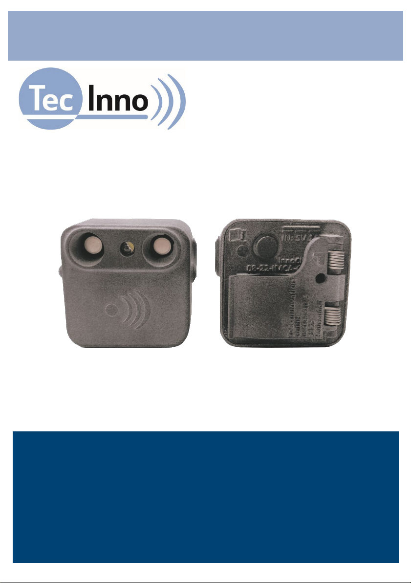
With the InnoMake Clip, obstacle detection is carried out using ultrasonic technology. The
distance to objects between 0.3 meters and optionally 1.0 meters, 2.0 meters or 4.0 meters
in walking direction is calculated and given as feedback. The measuring range of the
InnoMake clip is individually adjustable (s. section 4.5).
The calculation of the distance to objects in the walking direction is based on the reflection
of ultrasonic waves and the measurement of their transit time. During use, the sensors
continuously transmit and receive ultrasonic waves. The calculated distance to an object in
walking direction is given by vibration. The frequency of the vibratory feedback varies
proportionally to the measured object distance, i.e.
the closer an object is, the faster the vibratory feedback becomes
the farther you get away from an object, the slower the vibratory feedback becomes.
If the InnoMake Clip does not detect an obstacle within the set measuring range, no
vibration is emitted.
The InnoMake Clip is equipped with a rechargeable battery.
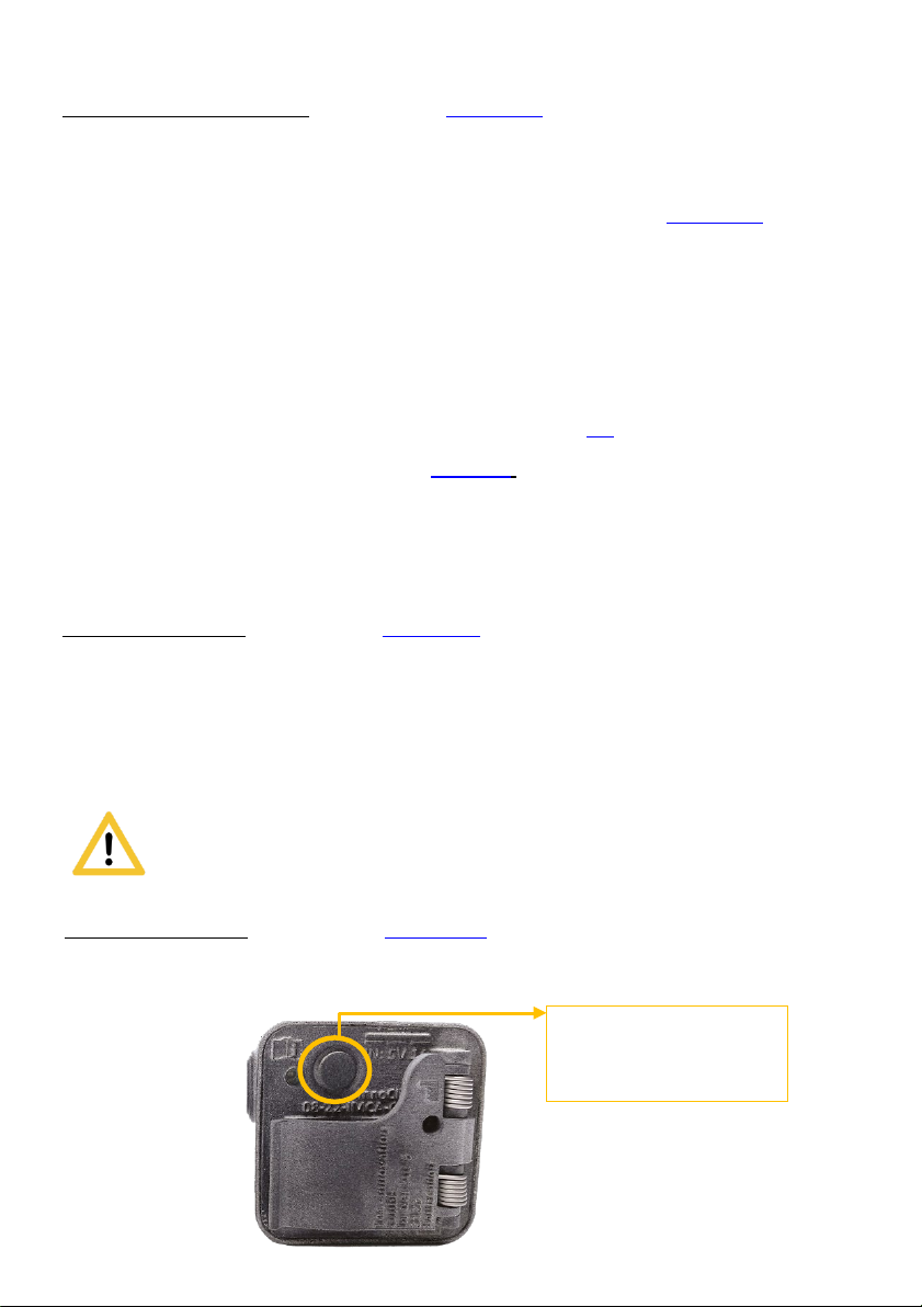
In section 4.10are type and duration of the signalling of the InnoMake Clip
can be found at a glance.
As a complementary mobility aid, the InnoMake Clip is not intended to
replace the primary aid, such as the cane or guide dog. Furthermore,
it cannot compensate for vision in terms of restoration.
The InnoMake Clip is used exclusively to compensate for the mobility impairment resulting
from a visual impairment, in particular severe visual impairment and blindness, and is only
to be used in the manner described here.
The use of the InnoMake clip to intentionally disturb living beings that can hear ultrasonic
frequencies and/or are sensitive to light is not permitted.

TDIMC1_4_User Manual_IMC-1.1.0_EN
9
3.1. Intended users
The InnoMake Clip is intended for use by people with impaired vision, in particular the
severely visually impaired and blind.
Since users operate the InnoMake Clip product on the one hand and experience the medical
benefits of the product on the other, they are both patients and operators in medical
terminology.
The user must therefore meet the physical and mental requirements for operating the
InnoMake Clip and for perceiving acoustic signals and mechanical vibrations. It should be
noted that vibration impulses can have negative effects on health in the case of certain
diseases of the nervous system. If a disease of the nervous system or a similar disease
exists, consultation with the family doctor is absolutely necessary before using the
InnoMake Clip.
Users of the InnoMake Clip do not require any formal education in the relevant field of
health care or a medical specialty.
The InnoMake Clip may not be passed on to other persons.
3.2. Area of application and environmental conditions
The InnoMake Clip is suitable for daily use indoors and outdoors.
However, use of the InnoMake Clip without a primary aid or without existing residual vision
is only permissible in familiar surroundings (e.g., home environment, suitable workplace),
where it is also safe to continue the journey unharmed in the event of any failure of the
InnoMake Clip.
The product is not intended for practicing sports or for extraordinary activities, such as
extreme sports.
Restrictions on use also apply in the event of extreme natural influences, such as floods, fire,
hail or at temperatures above 40°C and below-5°C, as well as in hazardous environments,
such as construction sites or workshops.
The permissible environmental conditions can be found in detail in the technical data in
section 7.
The InnoMake Clip does not detect holes in the floor or steps leading
downwards. Only objects rising from the ground are detected.

TDIMC1_4_User Manual_IMC-1.1.0_EN
10
4. Usage
4.1. Power on/off and ready state
Power on
The device is switched on by pressing the button on the back of the InnoMake Clip for at
least 2 seconds. An ascending audio signal indicates switching on. There is also a continuous
vibration during the sound signal. However, if the battery level is below 5%, there is no
continuous vibration during switching on (to save battery capacity). Excessive force when
pressing the push button could damage the housing.
Ready state
The operational state of the InnoMake Clip is signalled after switching on (rising audio
signal) and at the same time conveys the range to which the distance measurement is
currently set. A single short beep means a set range of 1.0 meters, two short beeps mean a
set range of 2.0 meters and three short beeps mean a set range of 4.0 meters. If a single
long beep is heard after switching on, then the set range deviates from the three levels
described, since this was last set via the app and is 1.5 meters, for example. In this case, by
briefly pressing the button on the back, you can choose between the three ranges and hear
the corresponding signal tones. In all of these cases, the signal tones also mean that the
InnoMake Clip is ready for operation.
The operational state can also be recognized by the fact that the range of the distance
measurement can be changed to the three ranges described above by briefly pressing the
pushbutton.
The default setting on delivery is 2.0 meters measuring range and the vibration feedback is
activated. All distance settings can be changed at any time by pressing the button or in the
app. Vibration feedback can only be disabled with the app.
Information about changing the measuring range is described in section 4.6.
Power off
To turn off the InnoMake Clip, press and hold the button for at least 2 seconds. A
descending tone signal indicates the device is switched off. A continuous vibration occurs
during the sound signal, which becomes weaker when the device is switched off. Excessive
force when pressing the push button could damage the housing.
4.2. Charging the battery
As described in section 2.1 on getting to know the product components, there is a push
button on the left side of the device when viewed from the front, with which the cover of
the micro USB socket on the opposite side can be pushed out of its anchorage. While the lid
is pushed out, turn it sideways to reveal the micro USB socket.

TDIMC1_4_User Manual_IMC-1.1.0_EN
11
To charge the battery, the charger with micro-USB plug that we have supplied must be used,
as the power pack meets the safety standards required for medical products. A bump can be
felt directly on the micro USB plug on one side, which is the international USB mark. This
tactile sign must point against the viewing direction of the InnoMake Clip when plugging it
into the micro-USB socket. Then connect the charger's power pack to a voltage source (220-
230V).
While the battery is charging, the LED, located on the back of the device right next to the
push button, will turn solid red.
The battery is fully charged when the LED colour changes from red to blue.
During the charging process, the charging status can be called up by pressing the push
button twice. (See the following section 4.3.)
After charging, disconnect the USB cable and close the micro USB socket again with the
cover turned to the side. All you have to do is press the button on the opposite side to lift
the lid to turn it back onto the micro-USB socket. The cover protects the micro USB socket
from foreign objects.
4.3. Battery charge-level query
The charge status of the battery is indicated by means of an acoustic and vibratory signal by
pressing the button on the back of the device twice in quick succession.
Four consecutive tones and vibrations indicate the charge status of the battery. High-
pitched tones indicate charged battery capacity, low-pitched tones indicate discharged
battery capacity.
The table below describes the five possible sound signals:
Acoustic signal Vibration signal State of charge
4x short low tones 4 weak vibration impulses 0% to 7 %
1x high and
3x low short tones
1 strong & 3 weak vibration
impulses
8% to 25%
2x high and
2x short low tones
2 strong und 2 weak vibration
impulses
26% to 50%
3x high and
1x short low tone
3 strong und 1 weak vibration
impulse
51% to 75%
4x short high tones 4 strong vibration impulses 76% to 100%
Example: When the device emits a high tone followed by three low tones, you know the
remaining battery charge is less than 26%.
The battery charge status can only be queried when the device is switched on.

TDIMC1_4_User Manual_IMC-1.1.0_EN
12
NOTE:
The proper execution of the primary aid must not be neglected
when using the InnoMake Clip.
NOTE:
The settings should be changed in idle mode!
4.4. First steps
Before using it for the first time, you should first familiarize yourself with the functions of
InnoMake Clip in your usual environment, for example by standing in front of a wall and
slowly moving towards or away from it, which increases or decreases the vibratory
feedback.
4.5. Change of the measuring range
Different, changing environments require similar adjustments to the measuring range of
InnoMake Clip.
The distance to objects is optionally output as feedback between 0.3 and 1 meter, between
0.3 and 2 meters or between 0.3 and 4 meters.
When ready for operation, the pushbutton on the back of the device can be used to switch
between the available measuring ranges.
To change the measuring range, a short press on the button is sufficient. The change of
settings is confirmed as follows:
Acoustic signal Vibration signal Set range
1 short tone 1 vibration impulse
measuring range of
1,0 meter
2 equal short tones 2 vibration impulses
measuring range of
2,0 meters
3 equal short tones 3 vibration impulses
measuring range of
4,0 meters
You can switch back and forth between the measuring ranges as often as you like. There
is a risk of damage to the housing if too much force is used when pressing the pushbutton!
The InnoMake Clip is delivered with a set measuring range of 2.0 meters. Changes to the
measuring range are saved and are retained after the unit is restarted.

TDIMC1_4_User Manual_IMC-1.1.0_EN
13
4.6. Activation/Deactivation of the intelligent mode (energy saving mode)
The InnoMake Clip is equipped with an intelligent mode which can be activated/deactivated
by pressing the pushbutton on the back of the housing.
When the intelligent mode is activated, the device detects when one is in front of a
permanent obstacle and stops the output of the current feedback.
Activation of the energy-saving mode is signalled to the user by decreasing vibration
strength.
The energy-saving mode is terminated by lightly tapping the housing. The termination of the
energy-saving mode is signalled to the user by increasing vibration strength.
To activate or deactivate the intelligent mode, press the pushbutton 4 times in quick
succession. The change of settings is confirmed as follows:
2 long, low tones followed by 1 short, high tone means the intelligent mode is activated
2 long tones followed by 1 short tone in the same pitch means the intelligent mode is
deactivated.
4.7. Activate LED
The LED is located on the front of the device, between the two ultrasonic sensors and
is used for better visibility.
To activate or deactivate the LED, press the pushbutton 3 times in quick succession.
The change of settings is confirmed as follows:
1 long low tone followed by 1 short high tone means the LED is activated
1 long tone followed by 1 short tone in the same pitch means the LED is deactivated.
4.8. After usage
When you have finished using the InnoMake Clip, you should switch off the device.
The following questions will help to prepare the InnoMake Clip for the next usage:
•Is the device switched off?
see: Power off in section 4.1
•Is the device dirty?
see: Cleaning in section 6.2
•Is the device moist?
see: Measures for environmental influences in section 5.2
•Is the battery of the device fully charged?
see: Charging the battery in section 4.2

TDIMC1_4_User Manual_IMC-1.1.0_EN
14
4.9. Warning tones of the InnoMake Clip
The InnoMake Clip emits certain warning tones in the following two situations:
1. Warning tone:
If the battery of the device is not charged for a longer period of time, it may happen that the
battery discharges during use. If this occurs, you will be informed by three identical tones
shortly before the battery is discharged and the system switches off. At the same time as
the acoustic warning signal, there is a continuous vibration. This is followed by a descending
sound signal as when the InnoMake Clip is switched off.
We recommend charging the InnoMake Clip after each use to prepare it for the next use.
Charging the battery is described in section 4.2.
2. Warning tone:
If the device heats up, e.g., due to high ambient temperatures, the electronics of the device
are automatically deactivated as a protective measure. Heating of the battery can also result
from excessive power consumption.
In order to be informed about the increasing heat development and not to be surprised by
the automatic shutdown of the system, an acoustic signal is emitted shortly before the
automatic deactivation.
In the situation described, a sequence of alternating high and low tones sounds, similar to a
siren. Simultaneously with the acoustic warning signal, a continuous vibration occurs. This is
followed by a descending sound signal similar to when the InnoMake Clip is switched off.
In the situation described, a sequence of alternating high and low tones sounds, similar to a
siren. Simultaneously with the acoustic warning signal, a continuous vibration occurs. This is
followed by a descending sound signal similar to when the InnoMake Clip is switched off.
In this case, we recommend allowing the product to cool down before touching the unit.
Further safety instructions and measures will follow in section 5.
4.10. Overview of the InnoMake Clip signals
The signals listed in the following table are only emitted when the InnoMake Clip is switched
on and active.

TDIMC1_4_User Manual_IMC-1.1.0_EN
15
Occurrence Keystroke Acoustic signal Vibratory
signal
LED-
Signal see
section
Power on 1x long 3x ascending tones 1x long impulse
4.1
Power off 1x long 3x descending tones
1x weakening
impulse
Operational state
Following "Switch
on" and corresponds
to the signal tone of
the last set
measuring range
1,0 meter
measuring range
set
1x short 1x short tone 1x impulse
4.6
2,0 meters
measuring range
set
1x short 2x equal short tones 2x impulses
4,0 meters
measuring range
set
1x short 3x equal short tones 3x impulses
Battery is loading red LED
(backside) 4.2
Battery loaded blue LED
(backside) 4.2
Battery charge:
0% – 7%
2x short
4x low short tones 4x weak
impulses 4.3
Battery charge:
8% – 25%
1x high and
3x low short tones
1x strong and
3x weak
impulses
4.3
Battery charge:
26% – 50%
2x high and
2x low short tones
2x strong and
2x weak
impulses
Battery charge:
51% – 75%
3x high and
1x low short tone
3x strong and
1x weak
impulse
Battery charge:
76% – 100% 4x high tones 4x strong
impulses
Activate LED 3x short 1x low long tone,
1x high short tone
1x short
impulse
followed by 1x
long impulse
4.8
Deactivate LED 1x long and
1x low short tone
2x short
impulses

TDIMC1_4_User Manual_IMC-1.1.0_EN
16
Occurrence Keystroke Acoustic
signal
Vibratory
signal
LED-
Signal see
section
Activate
intelligent mode
(starting with
firmware version
1.2.1)
4x short 2x long low tones, 1x
short low tone
2x short
impulses
followed by 1
long impulse
4.7
Deactivate
intelligent mode
(starting with
firmware version
1.2.1)
2x long and
1x short low tone
3x short
impulse
Battery empty (1.
Warning tone)
3x equal, then
3x descending tones
(like „Power off“)
Permanent
impulse
4.10
Device is
overheated
(2. warning
tones)
2x changing tones
(siren), then
3x descending tones
(like „Power off“)
Permanent
impulse
5. Safety instructions
The InnoMake Clip may only be used within the scope of its intended purpose as a
support for safe and personal locomotion. The use of the feedback is also intended
exclusively for the perception of the distance measurement within the scope of the
intended purpose.
The non-manipulated delivery condition of the InnoMake Clip is a prerequisite for
appropriate use. Modification or manipulation of the InnoMake Clip is not permitted.
The InnoMake Clip must not come into contact with acidic liquids.
If the ambient noise level is high, the sound signals may be too quiet. In such a situation,
it is absolutely necessary to pay increased attention to the vibration signals of the
InnoMake Clip.
If unusual heat development is detected, the unit must be switched off immediately.
As soon as the feedback from the InnoMake Clip can no longer be clearly perceived, the
dealer must be contacted.
Failure to observe alarms can lead to bodily injury or even damage to property,
especially if the device overheats, if obstacles are ignored
The InnoMake Clip must not be dried with hot air, e.g., a hair dryer, but only in the air at
room temperature.

TDIMC1_4_User Manual_IMC-1.1.0_EN
17
NOTE
:
Abrupt changes in the environment may result in functional limitations or unreliable
feedback.
5.1. Notes and measures in case of (mal)function of the product
Tipps, how to react to (mal-)functions of the InnoMake Clip.
Malfunctions Possible reasons Necessary actions
Dirt on the sensors Cleaning the InnoMake Clip see
section 6.2
Obstacle is out of the range of 0,3
and 4,0 meters
Approach to or distance from an
obstacle in the walking direction
to bring it into the measuring
range and obtain appropriate
feedback
An obstacle is not
detected
The material or shape of an object
can cause unfavourable ultrasonic
reflections, so that it is not
detected as an obstacle.
Pay attention to the proper
execution of the primary aid
during the application of
InnoMake Clip.
Ultrasonic sensors are covered by
clothing
Do not wear clothing that
interferes with vibration feedback
or obstacle detection
Obstacle lies centrally between the
ultrasonic cones
Pay attention to the proper
execution of the primary aid
while using the InnoMake Clip
An obstacle is
detected incorrectly
At a larger measuring range, objects
located to the side of the selected
walking direction may be detected,
as the measuring range of the
ultrasonic sensors becomes wider
in a conical shape in the distance.
Limitation of the measuring range
of the InnoMake Clip to 1.5
meters in order to reduce the
width of the ultrasonic cones
Loading-LEDs (red
and blue) light up
simultaneously
Hardware error Contact dealer

TDIMC1_4_User Manual_IMC-1.1.0_EN
18
NOTE
:
If the InnoMake Clip behaves in an incomprehensible manner or there are persistent,
unexpected malfunctions, the dealer must be contacted.
Malfunctions Possible reasons Necessary actions
An obstacle is
detected incorrectly
Foreign object on the sensor Removal of the foreign object
Surrounding sources of interference
in the same frequency range of the
ultrasonic sensors, such as a
clanking bunch of keys, other
ultrasonic sensors
Restart and wait until it is ready
for operation
An obstacle is
detected too late
The measurement range was
changed just before the obstacle
was detected
Stop and stand still while making
changes to settings.
Complete loss of
function and
deactivation of the
InnoMake Clip
Device is overheated
Allow the InnoMake Clip to cool
down before touching it again;
avoid skin contact.
Battery is empty Charge battery
Electrical or (electro-) magnetic
interference sources cause a failure
of the system
Restart the InnoMake Clip, the
settings and modes of operation
are retained
No warning tone
before automatic
deactivation
Software error Contact dealer
No LED- feedback
while charging the
battery
Device may have overheated;
charging was automatically
terminated
Allow the InnoMake Clip to cool
down before touching it again;
avoid skin contact; charge when
cooled down.
USB interface defect Contact dealer
Charger is not connected to power Connect charger to power
Ready-to-operate
state is not
established
Software error Restart the device, if necessary
charge the battery first

TDIMC1_4_User Manual_IMC-1.1.0_EN
19
5.2. Notes and measures in case of environmental influences
In this section, we provide information regarding external influences or environmental
conditions that may occur during the usage of InnoMake Clip.
Temperature
Since the electronics of the product are each equipped with protection against
overheating, the device may switch itself off due to high ambient temperatures (s.
section 4.10). This protects the user in particular, but also the battery.
The InnoMake Clip should be protected from direct sunlight during storage or transport.
The permissible temperature ranges of the environmental conditions can be found in
detail in section 7 technical data
Humidity
Extreme natural influences, such as downpours and muddy surfaces, can lead to
functional limitations.
The InnoMake Clip is not protected against salt water. However, if the product comes
into contact with salt water, it should be cleaned with a damp cloth.
If the product is wet when you finish using it, you can dry it with a cloth or let it air dry
completely. It is also recommended to open the USB port and place the device with the
open USB port facing down. This will allow any water that may have accumulated to leak
out of the waterproof USB port.
If the InnoMake Clip cannot be switched on after coming into contact with water or other
liquids, or if it emits a continuous vibration after being switched on, the application must be
terminated, and the dealer is to be contacted.
If malfunctions and functional failures occur due to devices in the home environment, it is
recommended to switch the InnoMake Clip off and on again. Restarting the system should
restore the full functionality of the InnoMake Clip.
Turning the InnoMake clip on and off is described in section 4.1.
Find examples of possible influences in a domestic environment which, among other things,
can cause the InnoMake Clip not to measure distances to obstacles as follows:
External electrical and electromagnetic influences
Devices with radio modules such as:
WLAN-router
WLAN-amplifier
Other devices with Bluetooth-connections

TDIMC1_4_User Manual_IMC-1.1.0_EN
20
NOTE:
It is essential to keep the InnoMake Clip and the USB charging cable out of the reach
of small children < 3 years of age. Due to the length of the USB cable of 1 meter,
there
is a risk of strangulation!
Exposure to magnetic fields
Transformers (except for low voltages, such as transformers in hi-fi systems),
devices with inductive charge, such as electric toothbrushes,
devices with electric motors, such as vacuum cleaners
Interference sources in the same frequency range
other ultrasound sensors
Clanging or high-pitched sounds, such as moved keychains
6. Handling
6.1. Storage and transport
It is recommended to ensure dry, low-dust storage and transport of the InnoMake Clip.
During storage and transport, the product should be protected from direct sunlight and
vermin as well as extreme heat and fire. The product must be kept away from heaters,
ovens or radiant heaters.
The permissible environmental conditions can be found in detail in the technical data in
section 7.
For returning the InnoMake Clip to the dealer or to us, the most suitable product
packaging for the return is the one in which the product was delivered.
6.2. Cleaning and disposal
We recommend regular cleaning of the product to positively support the longevity of the
InnoMake Clip.
In particular, the two ultrasonic sensors on the front of the product and the USB socket
including the pressure mechanism of the lid should be cleaned of dirt particles and dust at
regular intervals. If the device is dirty, functional restrictions may occur on the mentioned
product features.
For soiling in the area of the ultrasonic sensors, we recommend cleaning with a soft
commercial brush. When using a brush, care should be taken not to apply too much force
during cleaning to prevent damage to the electronics.
Table of contents
Popular Security Sensor manuals by other brands

Honeywell
Honeywell IS216 Features & specifications

Gewiss
Gewiss Chorus GW 10 786 Technical manual

Honeywell
Honeywell Ex-Or MLS2000DF Installation and commissioning instructions

Arch Environmental Equipment
Arch Environmental Equipment CTS 9000 IRRD Operation and installation manual

Lazer Safe
Lazer Safe LZS-003-HS Operation manual

Sonotec
Sonotec SONOCHECK ABD05 Series operating manual