Tecfluid MT03L Series User manual

R-MI-MT03L Rev.: 2 English version
Instructions manual
The art of measuring
Series MT03L
Electronic converter for level transmitters

2
Thank you for choosing the MT03L converter from MT03 series of
Tecfluid S.A.
This instruction manual allows the installation, configuration and
programming of the electronic converter MT03L. It is recommended
to read it before using the equipment.
• This document shall not be copied or disclosed in whole or in any
part by any means, without the written permission of Tecfluid S.A.
• Tecfluid S.A. reserves the right to make changes as deemed
necessary at any time and without notice, in order to improve the
quality and safety, with no obligation to update this manual.
• Make sure this manual goes to the end user.
• Keep this manual in a place where you can find it when you need
it.
• In case of loss, ask for a new manual or download it directly from
our website www.tecfluid.com Downloads section.
• Any deviation from the procedures described in this instruction
manual, may cause user safety risks, damage of the unit or cause
errors in the equipment performance.
• Do not modify the equipment without permission. Tecfluid S.A. is
not responsible for any problems caused by a change not
allowed. If you need to modify the equipment for any reason,
please contact us in advance.
PREFACE
WARNINGS

3
TABLE OF CONTENTS
1 INTRODUCTION ........................................................................... 5
2 RECEPTION ................................................................................. 5
2.1 Storage temperature ........................................................... 5
3 INSTALLATION ............................................................................. 5
3.1 Location ............................................................................. 5
3.2 Electrical connection ........................................................... 6
3.2.1 Power supply wiring ............................................... 6
3.2.2 Resistance input wiring .......................................... 7
3.2.3 Current input wiring ............................................... 7
3.2.4 Analog output wiring .............................................. 8
3.2.5 Relay output wiring ................................................ 9
4 OPERATION ................................................................................. 11
5 MAIN MENU ................................................................................. 12
5.1 Passwords to access the menus ......................................... 12
6 INSTALLATION PARAMETERS ...................................................... 14
6.1 Language ........................................................................... 15
6.2 Input .................................................................................. 15
6.3 Limits .................................................................................. 15
6.3.1 Capture ................................................................. 15
6.3.2 Distance adjustment .............................................. 16
6.4 Diagnosis ........................................................................... 16
7 PROGRAMMING PARAMETERS .................................................... 17
7.1 Language ........................................................................... 18
7.2 Units .................................................................................. 18
7.3 Decimals ............................................................................ 18
7.4 Damping ............................................................................ 19
7.5 Outputs ............................................................................. 19
7.5.1 Relay 1 and relay 2 ................................................ 19
7.5.1.1 Alarm ...................................................... 19
7.5.1.2 No action ................................................ 20
7.5.2 Analog output ........................................................ 20
7.5.2.1 Programming of the 4-20 mA output .......... 21
7.5.2.2 Current calibration for 4 and 20 mA .......... 21

4
8 SERIAL NUMBER .......................................................................... 21
9 SOFTWARE VERSION ................................................................... 21
10 BRIGHTNESS ............................................................................... 22
11 WORKING SCREEN ...................................................................... 22
12 MAINTENANCE ............................................................................ 22
12.1 Fuse .................................................................................. 22
13 ASSOCIATED SOFTWARE WINSMETER MT03 ............................... 22
13.1 USB cable connection and drivers installation ...................... 22
13.2 Port connection .................................................................. 24
13.3 Access to installation and programming ............................... 24
13.4 Visualization ....................................................................... 26
13.5 Firmware updates ............................................................... 27
14 TECHNICAL CHARACTERISTICS .................................................... 29
15 DIMENSIONS ............................................................................... 30
16 TROUBLESHOOTING .................................................................... 31
5
1 INTRODUCTION
MT03L converters are indicators for level measurement applications.
The electronic circuit is based on the most advanced technology in digital signal processing,
in order to obtain accurate and reliable measurements.
The equipment provides the following features (depending on the model):
• Graphic display with intuitive menus.
• Resistance input compatible with level transmitters series LE and transmitters LTE
from series LT, as well as with most of the level transmitters based in variation of
resistance.
• Analog input 4-20 mA.
• Level indication.
• Current output (4-20 mA) proportional to the level and user programmable.
• Relay outputs user programmable as level alarm..
2 RECEPTION
Converters of series MT03 are supplied conveniently packaged for transportation together
with their instruction manual for installation and operation.
All devices have been verified in our facilities.
2.1 Storage temperature
-20ºC ...... +60ºC
3 INSTALLATION
3.1 Location
The MT03L converter is housed in a box according to IEC 61554 standard. Its size is 96x96
mm and is intended to be mounted on a panel of a cabinet with a square hole of 90 x 90 mm
+0.5 mm / -0 mm. The cabinet should have a minimum depth of 90 mm behind the panel.
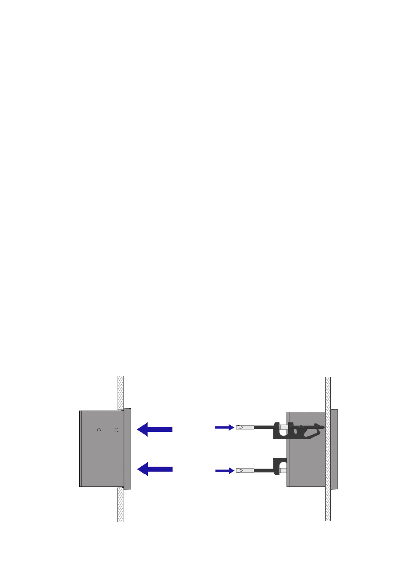
To place it into the cabinet, slide it through the front panel to the bottom as shown in the
following figure. Then screw the clamping arms until exert pressure on the panel.
6
3.2 Electrical connection
The connection of the equipment is via plug-in connectors, polarized to avoid mistakes when
plugged in. The connectors have screw terminals, as per VDE standards, to accept cables with
section of 1.5 mm2.
The pictures of the connections in this manual are always looking at the equipment from the
back.
To help in the wiring of the equipment, the description of the terminals is marked on a label
in the rear side of the device.
For the electrical installation it is recommended to use multiple conductor cables with
individual cable sections in the order of 0.25 to 0.5 mm2in order to make it easier to
connect. It is better to maintain the cables with mains voltage (power supply) separated from
the cables with low level signals (4-20 mA, etc.).
To connect the cables, peel the outside insulation to free the inner cables. It is
recommended to put a terminal at the ends of the wires to avoid loose ends.
Then, screw the wires into the corresponding positions in the female aerial connector.
Finally, place each connector with its corresponding male connector on the rear side of the
converter.
IMPORTANT NOTE: In order to comply with the electrical safety requirements as per EN-
61010-1 (IEC 1010-1), the installation of the equipment must take into account the following:
• The equipment must be installed in the front panel of an electrical mounting cabinet,
leaving only the front of the equipment accessible to the operator.
• In case of AC power supply, a mains switch must be provided to disconnect the
equipment. This switch must be marked as the disconnecting device for the
equipment and be within easy reach of the operator.
• The housing must not be opened when the instrument has mains supply
connected.
IMPORTANT NOTE: To ensure smooth operation of the equipment, it is recommended to
make the connection paying attention to the following points:
• For the output signals, use shielded cable when possible.
• Keep the cables away from strong sources of noise.
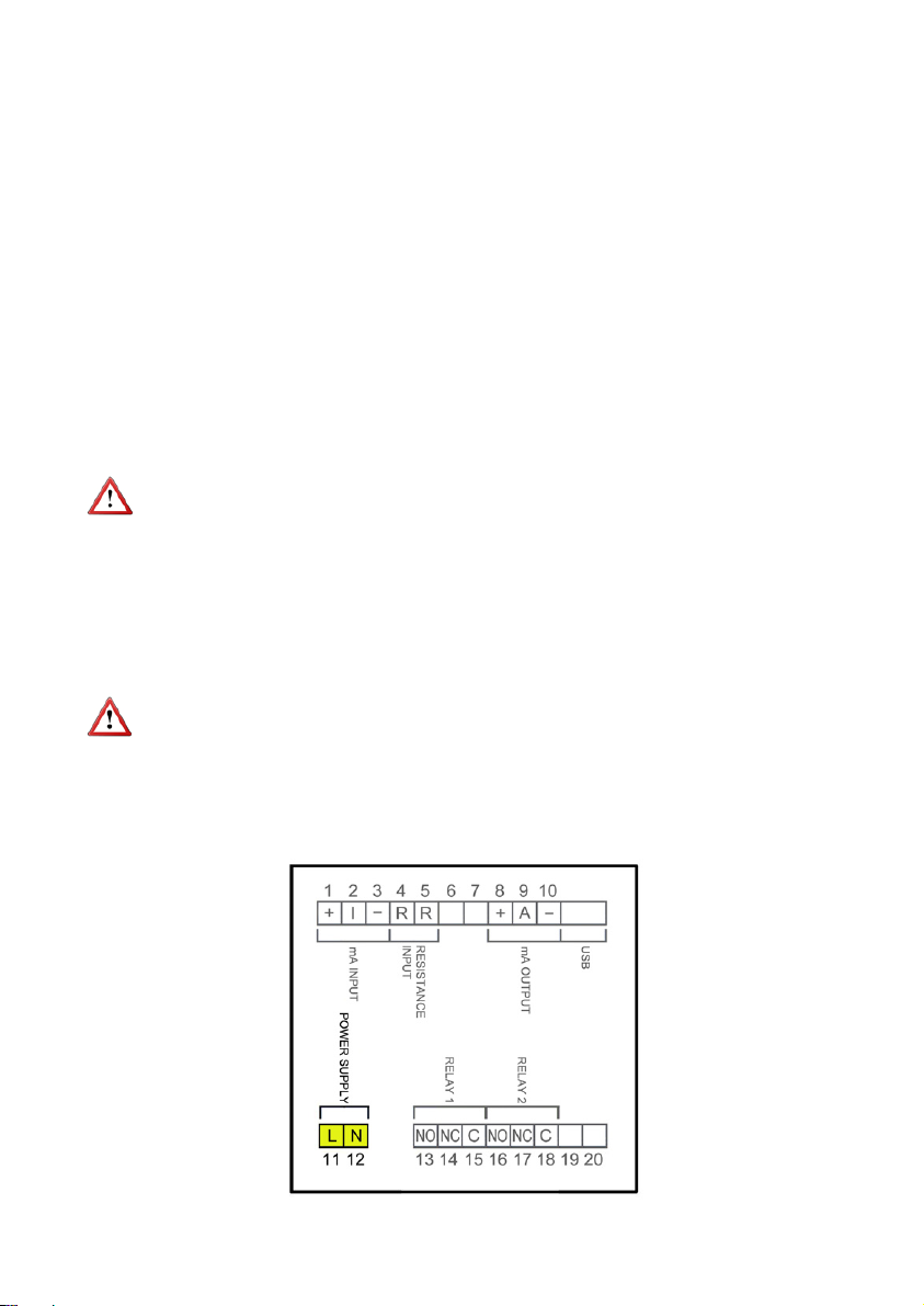
3.2.1 Power supply wiring
7
Before starting the wiring of the instrument, check that the supply voltage available is the
same as marked on the label of the converter.
Terminal Power supply AC Power supply DC
11 Phase DC
12 Neutral DC
In case of DC power supply, the equipment is provided by a diode bridge that allows
connecting it regardless of the polarity.
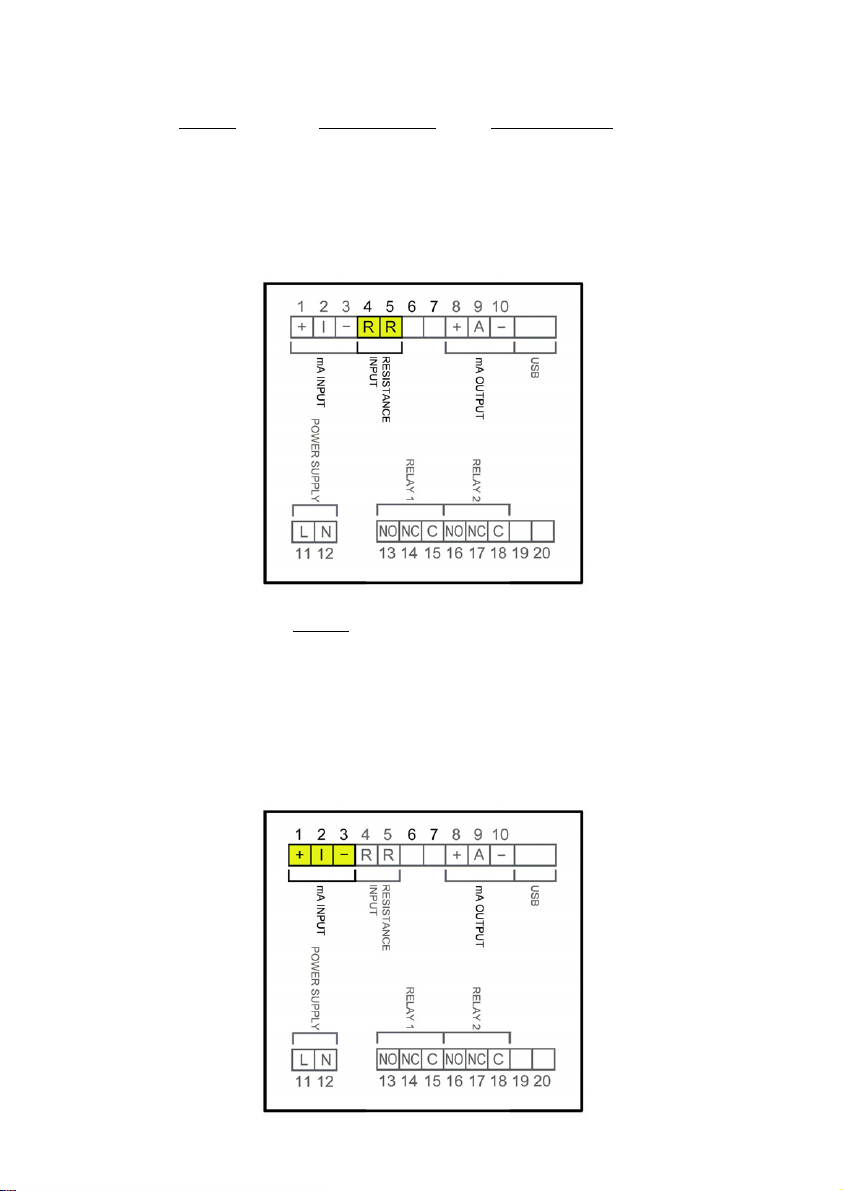
3.2.2 Resistance input wiring
Terminal
4 Resistance
5Resistance
This input is compatible with level transmitters of series LE and transmitters LTE of series LT,
as well as with other level transmitters based on resistance variation with values between 0
and 6500 Ω.
3.2.3 Current input wiring
8
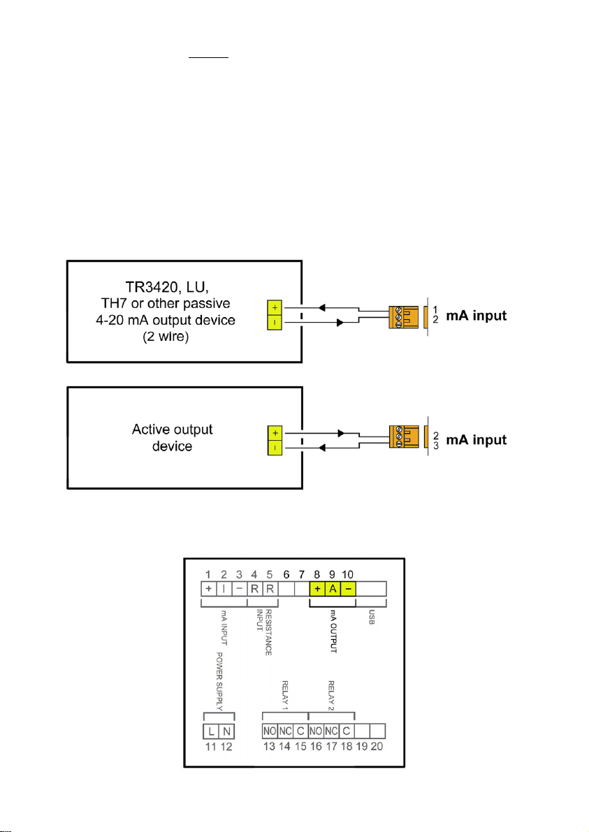
3.2.4 Analog output wiring
Terminal
1 mA (positive, power supply for a passive device)
2mA input
3 mA (negative, input from an active device)
This input is compatible with any flow rate transmitter that provides a 4-20 mA output.
The impedance is 120 Ω. The input has a protection in order to limit the voltage applied to
the circuit.
In the event that the current transmitter is passive, for example a 2-wire transmitter, it is
necessary to power the current loop. It is done by connecting the transmitter to terminals 1
and 2.
If the current transmitter is active, the connection is between terminals 2 and 3.
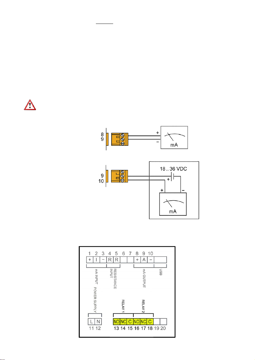
9
3.2.5 Relay output wiring
Terminal
8mA (positive, active output)
9mA
10 mA (negative, passive output)
The analog output is galvanically isolated. It can be either active (which means that the
receiving device must be passive) or passive (which means that the receiver must supply the
power for the current loop). It is recommended to use a receptor with an input resistance of
less than 700 to guarantee correct operation.
The configuration of the analog output mode (active or passive) is done by means of the
connection to the terminal strip. For active mode, terminals 8 and 9 are connected. For
passive mode, terminals 9 and 10 are connected.
NOTE: The analog output has a protection against reversed polarity. Due to another
protection against over voltages, if a loop supply voltage of more than 36 V is connected the
equipment may be damaged.
Active output
Passive output
10
Terminal Description Relay
13 Normally open Relay 1
14 Normally closed Relay 1
15 Common Relay 1
16 Normally open Relay 2
17 Normally closed Relay 2
18 Common Relay 2
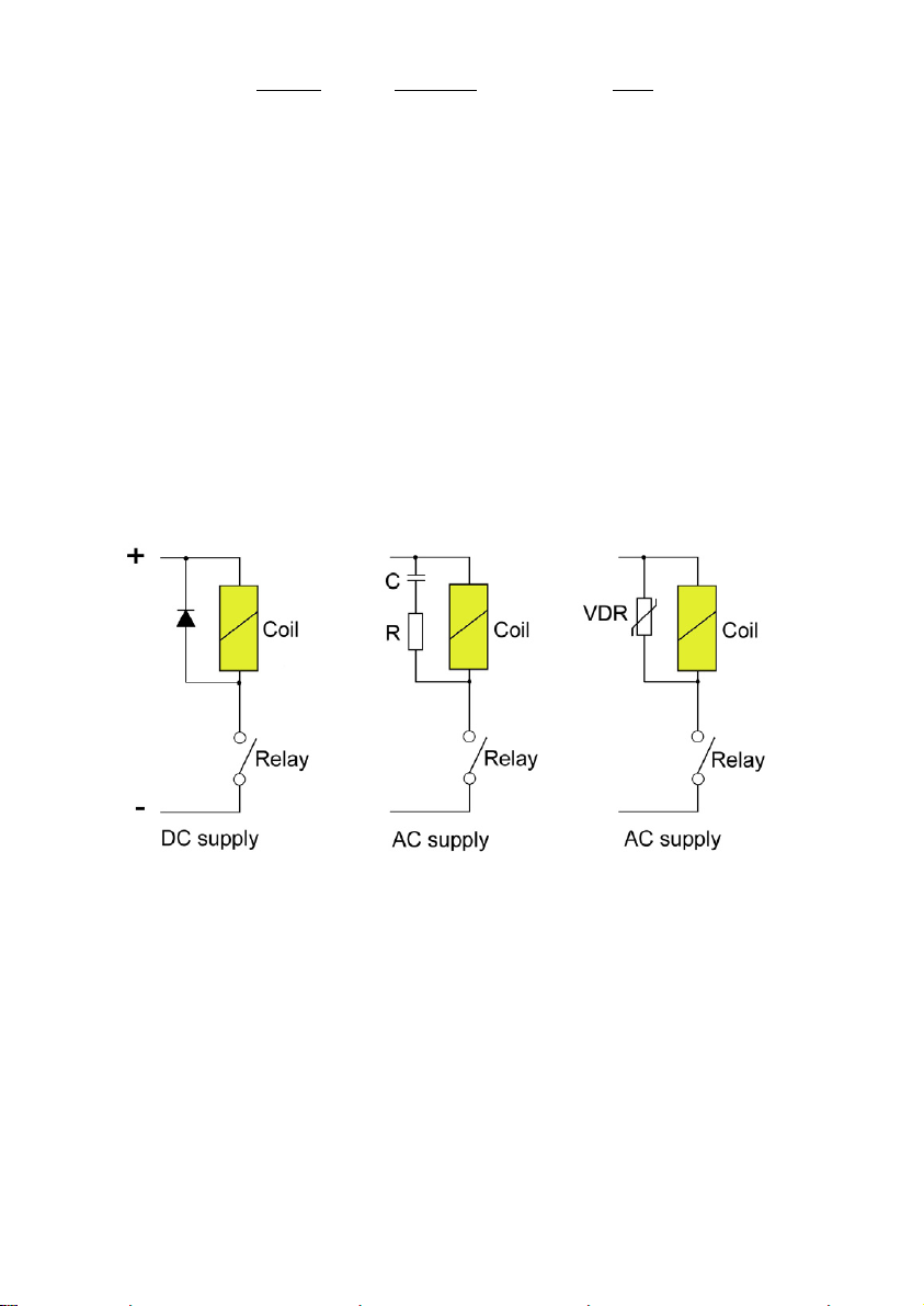
The relay outputs provide relays with potential free contacts (see characteristics on page 29).
The status of the relay contacts corresponds to the relay at rest.
The relay contacts are not protected in any way, and therefore they must be installed
externally as required in the application, taking into account the limitations of the
characteristics of such contacts.
In the case of having inductive loads, and to extend the working life of the relay contacts, it is
recommended to use overvoltage protection (VDR for AC and diodes for DC loads). In all
cases a fuse or some kind of protection against short circuits, should always be provided
according to the needs of the intended load.
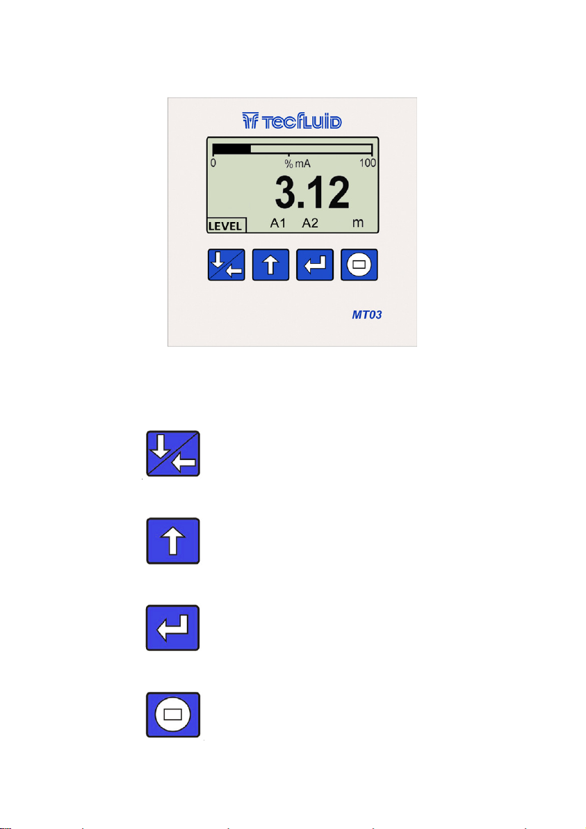
11
(Down / Left)
To change to the digit on the left.
Into the menu, to scroll down.
(Up)
To increase the digit.
To change the decimal point.
Into the menu, to scroll up.
(Enter) To validate the data.
To enter into installation and
programming modes of the converter.
To exit from an informative text.
(Escape)
To return to the previous menu. To exit
from a screen without validating data.
The following figure shows the functionality of the converter keys.
4 OPERATION
The MT03L converters have a graphic LCD and a keyboard with 4 push buttons.

12
To change the access password of
the installation menu, select
"Installation" on the main menu and
then "Password".
5 MAIN MENU
To access the main menu of the converter, press the key (Enter). The following screen
appears:
If you want to change any of these
passwords, you must enter the
corresponding menu and once inside,
access the submenu "Password".
The "Installation" option allows the basic configuration of the instrument, as explained in
Chapter 6 of this manual.
The "Programming" option allows to program all parameters of the converter, as explained in
Chapter 7 of this manual.
The options "Software Version" and "Serial Number" are informative and are discussed in
Chapters 8 and 9 of this manual.
5.1 Passwords to access the menus
The password for the installation menu may be different from the password for the program
menu.
By default, the equipment is factory configured with the password disabled.
Number of menu items
Selected item
13
To change the access password of the programming menu, select "Programming" in the
main menu and then "Password".
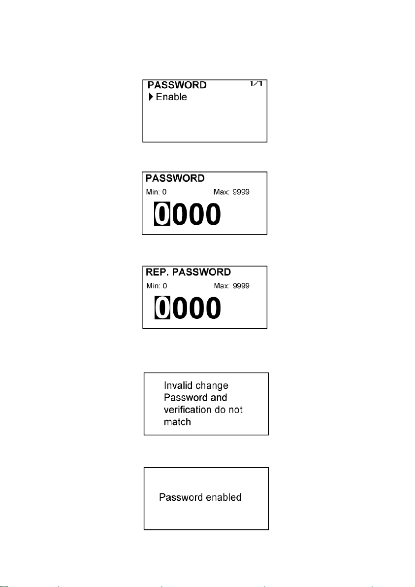
When the "Password" option is selected, a screen that indicates the password status for this
menu appears.
Selecting “Activate”, the screen to enter the new password appears.
Once entered, the new password is asked again to avoid possible inadvertent error.
If the re-entered password does not match the first one, the following error message
appears and the process should be carried out again.
If both passwords match, the following information message is displayed:

14
Once in the installation menu, the first screen allows to choose between the different
options.
6 INSTALLATION PARAMETERS
Power on the electronic converter with the voltage indicated on the label.
Press the (Enter) key in order to enter the main menu.
With the keys (Down / Left) and (Up), select “Installation”, and then validate with the key
(Enter).
If the converter has the password option enabled, a password must be entered. For more
details about the password, see section 5.1 on page 12.
If the password needs to be changed or disabled, the procedure is the same. Once entered
the "Password" menu, the following screen appears:
If Change is selected, the equipment will ask for a password again. If Disable is selected,
the following message will appear:

15
6.2 Input
In this screen the type of signal from the sensor connected to the MT03L can be chosen.
Resistance input is compatible with level transmitters of series LE and transmitters LTE of
series LT, as well as with other level transmitters based on resistance variation.
Current input is compatible with level transmitters of series LP and LTDR, as well as with
other level transmitters based on 4-20 mA output.
6.3 Limits
They set the relationship between the converter input signal and the displayed value.
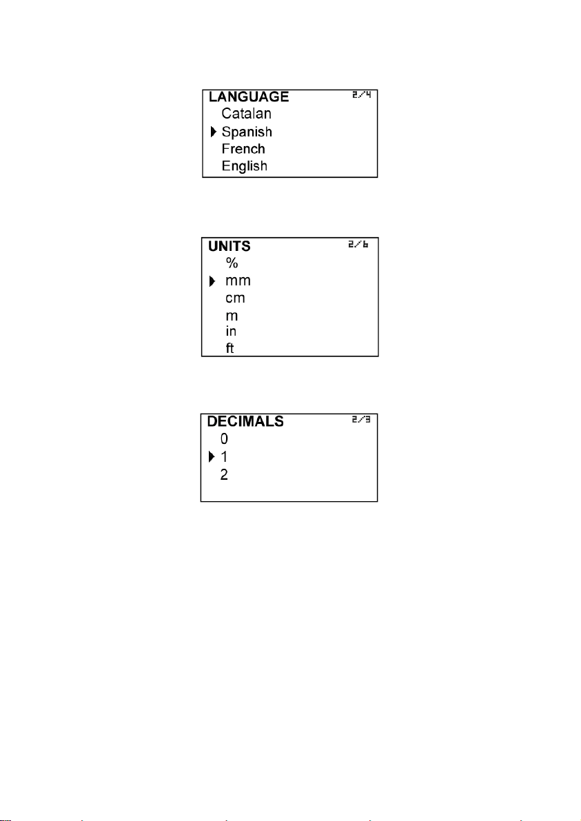
6.1 Language
The language in which all the menus will be displayed can be chosen.
6.3.1 Capture
This option is recommended only for those MT03L converters with resistance input, and which
must be connected to a level transmitter not purchased together with the converter or from
another manufacturer.
If the MT03L converter has been acquired together with a Tecfluid level meter, lower and upper
limit capture options are already configured at factory and their programming is not
recommended.
If the converter is connected to a level transmitter through the current input, captures will not be
normally necessary.

16
Selecting Yes, the device reads the input signal and sets the lower limit level.
The same procedure can be done with the capture of top level, placing the level meter at the
upper limit position.
6.3.2 Distance adjustment
The distance adjustment associates the level values previously captured with actual distances,
so that the converter can display the correct value.
In the same way as in the previous section, if the MT03L converter has been purchased with a
Tecfluid level meter, the distance adjustment is done at the factory. It is not recommended to
change these values.
In case of connection to a level meter previously acquired or from another manufacturer, if the
capture process has been already made (6.3.1), with the last two options of the menu, the
numeric values associated with the top and bottom level respectively can be entered.
To perform the capture options, set the level meter at the lower limit position (e.g. float in its
lowest position) and select the "Capture inf." with the key “Enter”. The following confirmation
screen appears.
NOTES: The values of lower and upper level are always entered in millimetres.
It is mandatory that the bottom level value is smaller than the top level value.
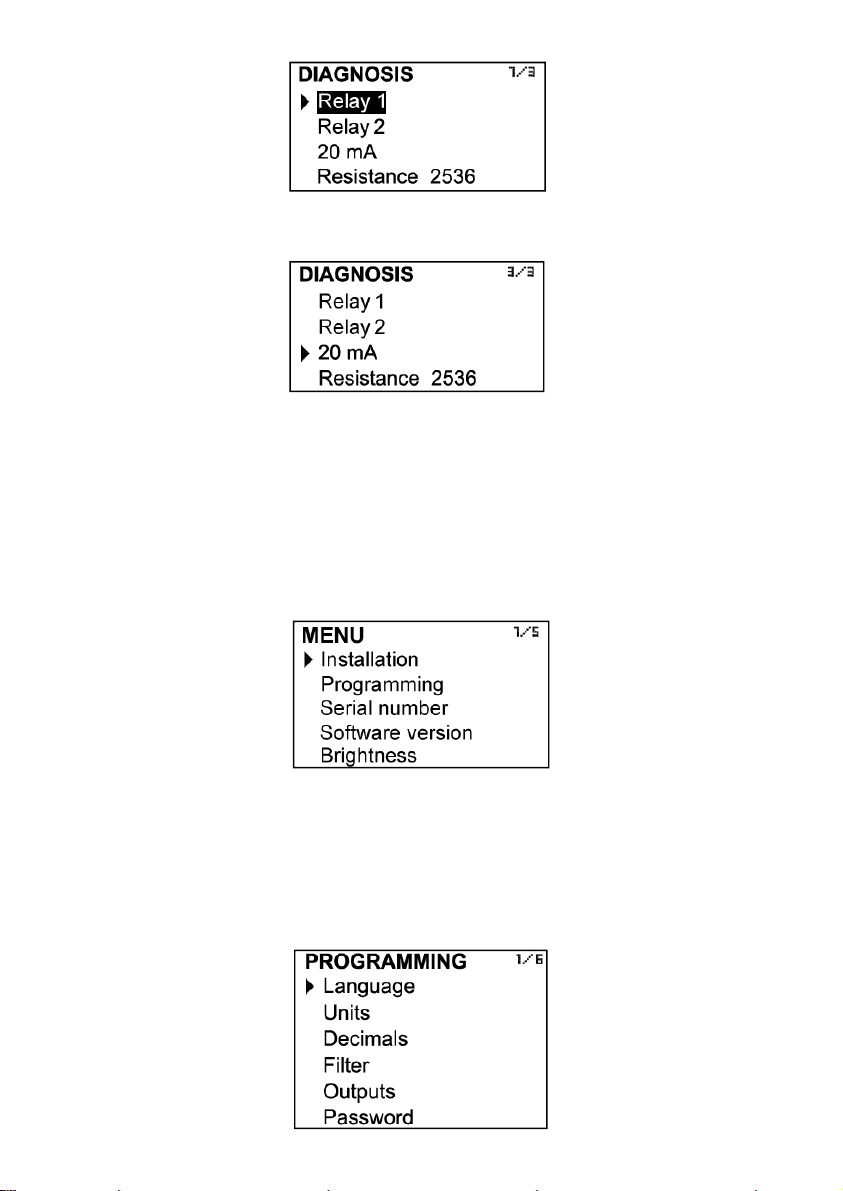
6.4 Diagnosis
It allows to check some parameters of the equipment.
Pressing the key (Enter) while selecting Relay 1 or Relay 2 will activate or deactivate this output.
When the relay is ON, the word is shown in reverse text.
17
Finally, in the last row, the selected input type and a number that is related to the value of
that input is shown. If when the level changes this number also changes, it means that the
converter receives signal from the level sensor.
7 PROGRAMMING PARAMETERS
By programming the converter, the visualization and the outputs of the instrument can be
configured.
Turn on the converter and press (Enter) to enter the main menu. The following screen
appears:
With the keys (Down / Left) and (Up), select Programming, and then validate with the key
(Enter).
If the converter has the password option enabled, a password must be entered. For more
details about the password, see section 5.1 on page 12.
Once in the programming menu, the first screen allows to choose between the different
options.
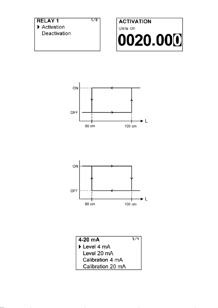
If 4 mA is selected, pressing the key (Enter) toggles between 4, 8, 12, 16 and 20 mA, allowing
to check the adjustment of the analog output.
18
7.2 Units
In this screen the units for the level indication can be chosen.
To select the number of decimals it must be taken into account that the instrument has 5
digits for level rate indication. If two decimals have been selected, these will be seen whilst
the level is not higher than 999.99. Above this value the indication will automatically change
to one decimal, and when the level is higher than 9999.9 the indication will be done without
decimals.
If one decimal is selected, the level indication will have a maximum of one decimal until
9999.9. Above this value the indication will be done without decimals.
If indication without decimals is selected, the level will always be shown without decimals.
For the selection of the level units and the number of decimals it must be taken into account
that an indication with an excess of decimals may give the sensation of instability of the
reading. As a general rule it can be considered that the reading should not have more than a
total of 5 digits (integer + decimals).
7.3 Decimals
In this screen the number of decimals for the level indication can be selected.
7.1 Language
You can choose the language in which all the menus will be displayed.
19
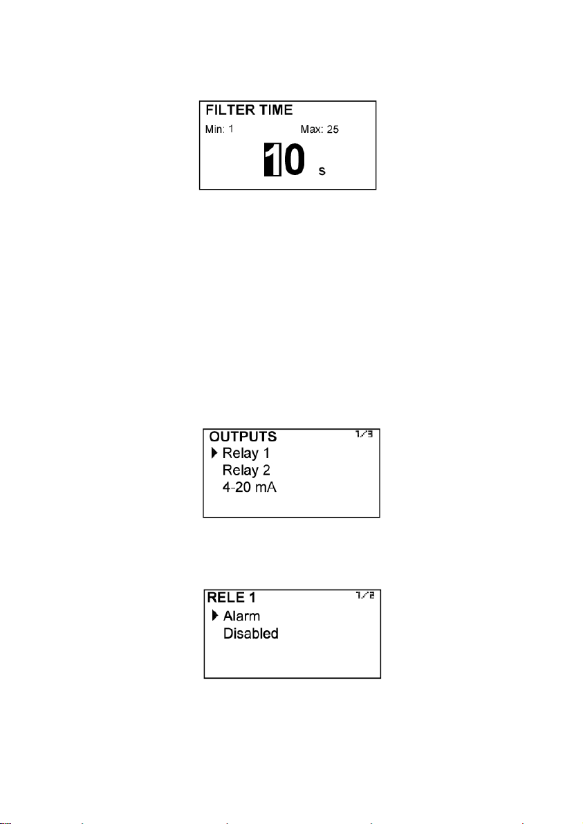
7.5.1 Relay 1 and relay 2
By selecting one of the two relay outputs, next screen appears with the options which allow
to assign the relay to a function.
7.5.1.1 Alarm
If Alarm is selected, we have access to program the level value at which the relays will
change its status and to the level of hysteresis. By level of hysteresis we understand the
difference between activation and deactivation of the output. To avoid that an alarm output
is continuously moving from activate to deactivate status, we must program the points of
connection and disconnection.
7.4 Damping
The MT03L converter has an adaptive filter (damping) to provide stable level and analog
output readings in the presence of continuous level fluctuations.
The configuration of this filter can be very useful in the cases where the level readings have
some instability (due to for example waves in the tank).
Only the level indication of the display and the analog output are affected by the filter. The
relay output acts according to the instant level. Selecting a filter with a longer or shorter
integration time will provide more or less stable readings and will also affect the response time
to small variations of level.
The integration time is selected in seconds, with a minimum value of 0 and a maximum value
of 25 seconds. For example, with an integration time of 15 seconds, the display will indicate
the level reading of the average level over the last 15 seconds from the last update of the
display. This does not mean that the display is refreshing its data every 15 seconds. The
display shows a new value several times per second, indicating an average of the level
values of the last 15 seconds.
7.5 Outputs
This screen allows to program the three outputs of the instrument: Relay 1, Relay 2 and
analog output (4-20 mA).
20
Example 1
If the activation point is programmed to 100 cm and the deactivation point is programmed to
90 cm, when the level is zero the output will be deactivated. When the level reaches a value
of 100 cm the output will be activated until the level falls below 90 cm.
Example 2
If we program an activation point of 90 cm and a deactivation point of 100 cm, when the
level is zero the output will be activated. When level reaches a value of 100 cm the output will
be deactivated until the level falls below 90 cm.
7.5.1.2 No action
The relay will be always at rest.
7.5.2 Analog output
The level value corresponding to 4 mA and 20 mA can be programmed and the calibration
for these two values can be made as well.
Table of contents
Other Tecfluid Media Converter manuals


