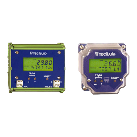
Tecfluid CI-420 User manual

TABLE OF CONTENTS
1 PRINCIPLE OF OPERATION ............................................................... 2
1.1 Limitations ……………….……………………………..………. 2
2 INSTALLATION………………………………………………………..……. 2
2.1 Mains connection ………………...……………….………...… 2
2.2 Input connection…………………...……………….…….……. 3
2.2.1 Pick-up input.................................................................. 3
2.2.2 Electrical contact input.................................................. 3
2.3 Analog output connection………………………………….... 4
2.4 Pulse output connection……...……………………………… 4
3 SETTING UP…………………………………………………………………. 4
4 CONFIGURATION……………………………………………………...…… 5
5 TECHNICAL CHARACTERISTICS………………………………..….……6
5.1 Working conditions………………………...……….….……… 6
5.2 Mains supply……………………………………...….….……… 6
5.3 Analog output…………………………………….….………… 6
5.4 Pulse inputs……………………………..………….…...……… 6
5.5 Pulse output……………………………………….……….…… 6
5.6 Norms…………………………...………………….……………. 6
5.7 Dimensions………………………………………...…………… 7
CI-420
pulse / mA
Converter
Instruction Manual
R-MI-CI420 Rev.: 2 English Version
instrumentación
para fluidos

2
1PRINCIPLE OF OPERATION
The CI-420 converter has been designed to generate an analog output which is proportional to the
input frequency and at the same time an opto-isolated pulse output the same as the input. All the
mathematical functions are made by a microprocessor that also filters the output to give a stable
reading.
The relationship between the current output and the input frequency is:
Io= Output current
Ii= Initial Current (Beginning of the Scale)
Ir= Current range
fe= Input Frequency
fr= Full Range Frequency (Frequency for maximum output)
The value of Ii(Initial Current) and Ir(Current range) are selected by means of two jumpers inside the
instrument. The values of these currents for the beginning and full scale are:
Beginning of Scale IiFull Scale Current Range Ir
0 mA 20 mA 20 mA
4 mA 20 mA 16 mA
By means of another two jumpers the current output can be changed for voltage outputs to obtain
the following voltage outputs:
Beginning of Scale Full Scale
0 V 5 V
0 V 10 V
1 V 5 V
2 V 10 V
The value of fr(the full scale frequency) is selected by means of four BCD switches below the front
panel. Four jumpers are provided to select the decimal point position.
1.1 Limitations
The minimum frequency that the instrument will detect is 0,04 Hz (one pulse every 25 seconds).
The maximum input frequency is 2.000 Hz.
2. INSTALLATION
The CI-420 is housed in an IP40 plastic case for mounting on a panel inside an electric control panel.
The plastic case has two holes for mounting with screws to DIN 46 121 and DIN 43 660, and also it
has a snap fastener for fitting to DIN 46 277 and DIN EN 50 022 assembly rails.
Screw terminals are provided for the external wiring. The terminals are protected against accidental
contact in accordance with VDE 0100 Part 750, VDE 0160 Part 100 and VBG 4.
2.1 Mains connection
The mains supply voltage is connected to terminals 1 and 2. The mains voltage is indicated on
the label at the side of terminals 1 & 2.
f
f
x
I
+
I
=
I
r
e
rio

3
IMPORTANT : In order to comply with the safety requirements as per IEC 1010-1, a mains
switch must be provided to disconnect the equipment. This switch must be marked as the
disconnecting device for the equipment and be within easy reach of the operator. The equipment
must be installed inside an electrical mounting cabinet to avoid the possibility that the operator
may touch a connection terminal.
2.2 Input connection
The CI-420 is designed to be able to work with two types of inputs.
2.2.1 Pick-up Input
For the input from turbine type flowmeters which use magnetic inductive pick-ups to detect
the movement of the turbine blades, the wiring must be made as following:
CI-420 Terminal No.Pick-up Terminal No.
14 shield 1 shield
15 live 2 live
16 live 3 live
"live" means the two ends of the pick-up coil.
The input cables must not be installed close to mains cables as these can induce
errors due to electrical interferences.
2.2.2 Electrical contact input
For connecting inputs from reed switches etc., as one can find for example in COVOL
flowmeters, the wiring must be made as following:
CI-420 Terminal No.COVOL Terminal No.
14 shield 1 shield
15 no connection
16 live 2 live

The shield is connected to one end of the reed switch and the live to the other end.
A pulse generator with an open collector output (NPN transistor) can be connected to this
input mode. In this case the emitter (or common) must be connected to terminal 14 and the
collector to terminal 16.
2.3 Analog Output Connection
The analog output connected to terminals 9 and 10. Terminal 9 is the positive of the output and
terminal 10 is the negative (common).
When the instrument is used for a current output then the load applied to the output should be
less than 600 ohms.
When the instrument is used for a voltage output then the load applied to the output should be
greater than 10,000 ohms.
4
3. SETTING UP
Once the instrument is installed the
only thing that has to be done is
setting the frequency which must de
applied to the input frequency to
obtain the full scale analog output.
To introduce this frequency we have
four BCD coded switches and a
jumper with four positions. With the
four BCD coded switches we select
the four significant digits and with the
jumper we select the position of the
decimal point. To get to the switches,
a screwdriver can be used to lever out
the top cover, which is just clipped in
its place.
The jumper must be in one of the
four positions provided. The
instrument will not work correctly if
the jumper is not in one of the four
positions.
2.4 Pulse output connection
Terminal 12 is the emitter of an opto-
isolated NPN transistor and terminal 11 is
the collector.
This output can be used to activate
electromagnetic units such as DC
counters or relays.
No protections for excess current or
voltage spikes are provided. These
should be installed externally as required. Example of connection to a PLC
CI-420
PLC
12
+ 24 V
0 V
Input
Connection to a PLC with a "PNP" input
11
0
0
0
0
0
0
0
0
0
0
0
0
4
4
4
4
4
4
4
4
4
4
4
4
9
9
9
9
9
9
9
9
9
9
9
9
3
3
3
3
3
3
3
3
3
3
3
3
8
8
8
8
8
8
8
8
8
8
8
8
2
2
2
2
2
2
2
2
2
2
2
2
7
7
7
7
7
7
7
7
7
7
7
7
1
1
1
1
1
1
1
1
1
1
1
1
6
6
6
6
6
6
6
6
6
6
6
6
5
5
5
5
5
5
5
5
5
5
5
5
1
1
1
2
2
2
3
3
3
0000
4
4
4
4
9
9
9
9
3
3
3
3
8
8
8
8
2
2
2
2
7
7
7
7
1
1
1
1
6
6
6
6
5
555
1234
4
4
4
Frequency = 13,29 Hz
Frequency = 521,3 Hz
Frequency =1,234 Hz
Frequency = 1234 Hz

5
In the examples given, the jumper is shown as a black filling.
In the four examples we can see how to program the frequency which corresponds to the maximum
output.
When changing the maximum frequency, this should be done with the instrument disconnected from
the mains supply. The instrument reads the switch data only when it is switched on.
4. CONFIGURATION
It is not normally necessary for the user to have to change the basic configuration of the instrument,
given that the CI-420 is supplied according to the clients specifications.
In the example given the instrument is configured for a COVOL input and 4-20 mA output.
The JP1 and JP2 jumpers are used to configure the type of input and should not be moved
The jumpers JP3, JP4, JP5 & JP6 are used to configure the type of output.
Beginning Full JP3 JP4 JP5 JP6
of Scale Scale 1 2
1. 0 mA 20 mA X X
2. 4 mA 20 mA X
3. 0 V 5 V X X X X
4. 0 V 10 V X X X
5. 1 V 5 V X X X
6. 2 V 10 V X X
Jumpers JP5 and JP6 are used only for voltage outputs, and have only one position.
Jumper JP3 fixes the full scale range.
Jumper JP4 is used to determine the beginning of the scale and has two positions, "1" towards the
top of the PCB and "2" towards the bottom of the PCB.
The jumpers should be placed in the position marked with "X".
The potentiometer POT1 can be used for fine adjustment of the full scale reading.

6
5. TECHNICAL CHARACTERISTICS
5.1 Working conditions
The case has a protection as per IP 40 and the terminals as per IP 20.
The working temperature limits are –10 to 60oC
5.2 Mains supply
The standard mains voltage is 230 Vac 50/60 Hz. AC Mains voltages of 240 V, 110 V y 24 V
50/60 Hz. and 24 Vdc supply voltage are available on order.
The power consumption is less than 1 W.
The instrument is not supplied with a mains filter and in the exceptional cases that, due to high
levels of mains interference, a mains filter is needed, this must be installed externally. Due to the
low power consumption, almost any small mains filter will be adequate.
The instrument is supplied with a slow blow (T) 250 mA fuse.
5.3 Analog Output
The analog output is configured internally for current or voltage output.
Current Output - Maximum Load = 600 ohms
Voltage Output - Minimum Load = 10.000 ohms
5.4 Pulse inputs
1. The input called "COVOL" is designed to work with an electrical contact which closes the
circuit between terminals 14 and 16 of the terminal strip. Given that this type of input is generally
slow and to avoid contact bounce, this input is limited to about 200 pulses per second.
2. The pick-up input is designed to work with an inductive pick-up using a coil. The input
frequency in this case is limited to about 2,000 pulses per second.
5.5 Pulse Output
Frequency : The same as the input frequency (max. 2000 Hz).
The opto isolated open collector has the following characteristics:
NPN Transistor
Maximum Voltage : 30 Vdc
Maximum Current : 50 mA
5.6 Norms
Conforms with Directives 89/336/CEE (EMC) and 73/23/CEE (Low voltage)

7
5.7 Dimensions
In the following drawings the outside dimensions and the layout of the fastening holes for screws
are given. The layout of the fastening holes is given looking at the top of the instrument.
The weight of the instrument is approximately 300 g

TECFLUID, S.A.
Narcís Monturiol, 33
E-08960 Sant Just Desvern
Tel. + 34 933 724 511 - Fax + 34 934 734 449
E-mail: [email protected]
Internet: www.tecfluid.com
The technical data in this pamphlet is subject to modification without notification, if the technical innovations in the product or
manufacturing processes so require.
WARRANTY
Tecfluid S.A. GUARANTEES ALL ITS PRODUCTS FOR A PERIOD OF 24 MONTHS, after
consignment, against all defects in materials and workmanship.
This warranty does not cover failures which can be imputed to misuse, use in an application different
to that specified in the order, the result of service or modification by un-authorized persons, bad
handling or accident.
This warranty is limited to cover the repair or replacement defective parts which have not been
damaged by misuse.
This warranty is limited to the repair of the equipment and all further and eventually following
damages are not covered by this warranty.
Any consignment of equipment to our factory or distributor must be previously authorised. The
consignment should be done with the equipment well packed, clean of any liquids, grease or
hazardous materials. Tecfluid S.A. will not accept any responsibility for damage done during
transport.
Together with the equipment, a note should be enclosed indicating the failure observed, the name,
address and telephone number of the sender.
Table of contents
Other Tecfluid Media Converter manuals
