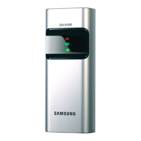
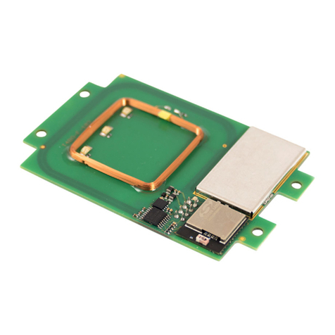
TECH FASS MREM 81 MTM User manual

MREM 81 MTM(VR)
RFID module 125 kHz

Introduction
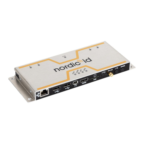
RFID reader module MREM 81 MTM (125 kHz) with integrated controller for one door
control is designed either for connection to the RS 485 bus of the APS mini Plus access
system or for autonomous operation. The module is also equipped with a Wiegand
interface for connecting an input RFID reader with a Wiegand output for possible both-
sided controlled door. Up to 32 MREM 81 reader modules can be connected to one RS
485 communication line of the APS mini Plus system. The module is dedicated either
as a standalone or as a part of modular entry panel MTM from CAME.
a. Application
▪Access control system, booking system
▪Door access control, both-sided access control
▪Lift access control
b. Parameters
▪Input voltage 8 ÷ 28 Vdc
▪Typical current consumption 60 mA @ 12 V
▪Maximum input power 1,5 W
▪Reading id media EM Marin, Jablotron
▪1x RS 485 (system bus APS mini Plus)
▪1x Wiegand (external RFID reader, GSM module, license plate camera)
▪1x Open drain transistor output 30 V / 1 A
▪2x INPUT (door contact, exit button, tamper)
▪Integrated in module MTMRFID
c. Variants
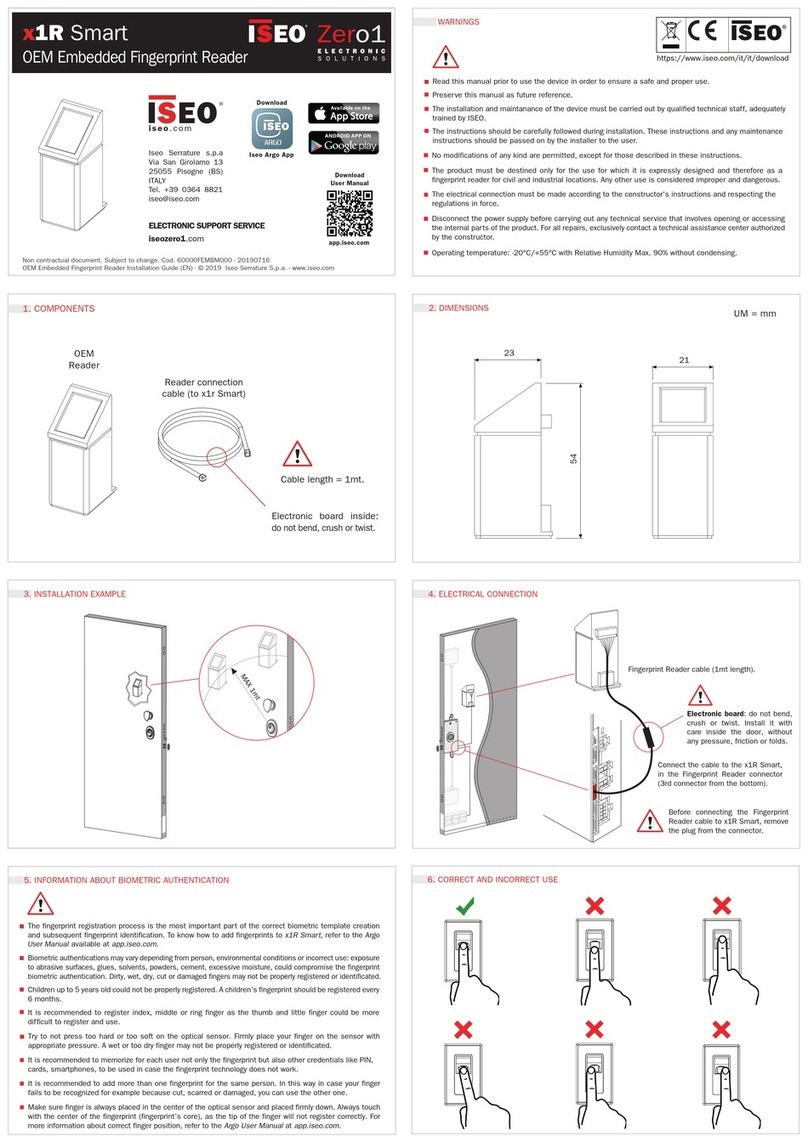
Product variants in aluminium, silver color
CATALOG NUMBER
PART NUMBER
SYSTEM
VARIANT
RFID frequency
53481001
MREM 81 MTM - EM
APS mini Plus
Modul MTMRFID
125 kHz
* For 13,56 MHz (MIFARE®, NFC) please check MREM 82 MTM product raw.
Product variants in zamak, black color
CATALOG NUMBER
PART NUMBER
SYSTEM
VARIANT
RFID frequency
53481011
MREM 81 MTMVR - EM
APS mini Plus
Modul MTMRFID
125 kHz
* For 13,56 MHz (MIFARE®, NFC) please check MREM 82 MTMVR product raw.
d. Marking
MIFARE®a MIFARE Classic®are registered trademarks owned by NXP B.V.
Android®is registered trademark owned by Google LLC.

e. Block diagram
The MREM 81 MTM(VR) reader module is a module for the MTM modular entry panel. MTM entry panel itself is part of
the home phone system, it has its own power supply and bus for phones. MREM 81 MTM has its own cabling, data bus
of the APS mini Plus access system and the power supply can either be used from the MTM panel or have a 12V / 24V
power bus for the APS mini Plus access system.
▪Complete door control; lock control (open drain), door contact input, exit button, alert notification to PC or Cloud,
wiegand input, system bus, power supply. The reader module can operate autonomously or as a part of the
system.

▪Connection on the RS 485 bus with control from a mobile phone from the WebHit cloud application. Up to 32
reader modules can be connected to one APS mini Plus line.
•How to connect in ‘‘star‘‘? Using the REP 485 line repeater.

Content
1Technical parameters...............................................................................................6
1.1 Electrical parameters..................................................................................................6
1.2 Communication interface............................................................................................6
1.3 Mechanical parameters ..............................................................................................6
2Assembly...................................................................................................................7
2.1 Cable connection of MREM 81 MTM(VR) ..................................................................7
2.2 System bus.................................................................................................................8
2.3 Assembly....................................................................................................................8
3RFID reading .............................................................................................................9
3.1 Reading at 125 kHz....................................................................................................9
4Wiring diagram ......................................................................................................10
4.1 Connection possibilities MREM 81 MTM(VR) ..........................................................10
5Settings ...................................................................................................................13
5.1 Setup procedure.......................................................................................................13
5.2 HW address setting ..................................................................................................13
5.3 Meaning of LED indicators .......................................................................................14
5.4 Configurable parameters..........................................................................................15
6Operating modes....................................................................................................16
6.1 Standard operating mode.........................................................................................16
6.2 External reader with Wiegand output .......................................................................17
7Function ..................................................................................................................18
7.1 Functions of the reader module................................................................................18
7.2 Function ‘‘Door open‘‘...............................................................................................18
7.3 Permanent lock release based on valid time schedule ............................................18
7.4 Function of ID with flag.............................................................................................18
7.5 ID expiration .............................................................................................................19
7.6 Antipassback function (APB)....................................................................................19
7.7 Disabling the reader module.....................................................................................19
7.8 Alerts and their signaling..........................................................................................19
7.9 Simplified access rights model .................................................................................21
7.10 Offline setting (programming) mode.........................................................................21
8Other........................................................................................................................25
8.1 Legislation ................................................................................................................25
8.2 Declaration of conformity..........................................................................................25
8.3 Electrical waste.........................................................................................................25

www.techfass.com RFID reader module MREM 81 MTM(VR)
1Technical parameters
1.1 Electrical parameters
PARAMETER
CONDITION
MIN
MAX
UNIT
Input voltage Vin
8
28
V
Typical current
consumption Iin
Vin = 8 V
Vin = 12 V
Vin = 24 V
75
53
30
mA
mA
mA
Peak current
consumption Iin
Vin = 8 V
Vin = 12 V
Vin = 24 V
106
73
42
mA
mA
mA
Typical input power
0,7
W
Maximum input power
1,1
W
Typical reading
distance (ISO card)
125 kHz (EM Marin)
3
5
cm
RTC
Backup
24
h
Memory
ID media
Events
Time plans
2000
3400
64
pc
Signalization
RGB led
Piezo
1
1
pc
1.2 Communication interface
INTERFACE DESCRIPTION
TECHNOLOGY
PROPERTIES
System data bus
RS 485
19 200 bit / s, 8 data bits, even parity, 1 stop bit
Wiegand
Wiegand / RS 485
Formats 26, 32, 34, 37, 44, 46, 56 bits, custom
1.3 Mechanical parameters
PARAMETER
MREM 81 MTM
MREM 81 MTMVR
JEDNOTKA
Weight
122
g
Dimensions l x w x h
137,5 x 136 x 64 (34)
mm
Mounting
Wall-mounted or recessed
Color & design
Silver, aluminium
Black, zamak
Environment class
IV –outdoor general device,
-25 ÷ +70
oC
IP code
IP 54
IK code
IK 07
IK 09
cable
10 wires, 3 x 0,4
m

www.techfass.com RFID reader module MREM 81 MTM(VR)
2Assembly
2.1 Cable connection of MREM 81 MTM(VR)
Cable of MREM 81 MTM(VR) contents 10 wires with following functions:
MREM 81 MTM(VR)
NUMBER
COLOR
WIRE DESCRIPTION
WHERE IT LEADS (EXAMPLE)
1
Purple
OUT 1; 30 V, 1 A, open drain
Lock (connecting to GND)
2
Blue
GND
Power supply GND
3
Red
Power supply Vin 8 ÷ 28 Vdc
Power supply
4
Pink
Wiegand data 1
Wiegand reader (both sided control)
5
Green
Wiegand data 0
Wiegand reader (both sided control)
6
Gray
IN 2 (input 2), configurable funciton
Exit button
7
Yellow
IN 1 (input 1), configurable function
Door contact
8
Brown
Signal ground 0 V
Ground for input signals (door contact,..)
9
White
Signal B system data bus
APS mini Plus system bus
10
Black
Signal A system data bus
APS mini Plus system bus
2.1.1 Inputs and Outputs
INPUT / OUTPUT
DESCRIPTION
Input 1 (IN 1)
Door contact, active when door closed; REX button
Input 2 (IN 2)
Request to exit button or handle contact, active when button or handle pressed; Tamper; Disabling
function
Output 1 (OUT 1)
Door lock control (open drain)
Output 2 (OUT 2)
Alert output (open drain)

www.techfass.com RFID reader module MREM 81 MTM(VR)
2.2 System bus
2.2.1 RS 485 bus termination
If the reader module is the last one on the bus, it is advisable to terminate the RS 485 system bus so that there is no
reflection on the line. Use the termination resistor 150Ω which is a part of the packaging.
2.2.2 RS 485 idle states
This reader module does not allow to set the idle states of the system bus. Set the idle states on converters APSLAN,
CON 110.IP or REP 485 if needed.
2.3 Assembly
2.3.1 Radio signal interferences
If a 125 kHz reader is used, it is necessary to take into account another 125 kHz reader in direct range - for example when
checking the door on both sides. In this case, the readers may interfere with each other. In the techfass system, it is
possible to use the so-called synchronization of reading between the reader and the reading module, which then do not
interfere with each other.
In general, if possible, we avoid mounting on metal substrates, it is recommended to perform a practical reading test or
contact support@techfass.cz.
Interference along the line, e.g. from an interfering power supply, can affect the reading distance or the reader's own
communication.

www.techfass.com RFID reader module MREM 81 MTM(VR)
3RFID reading
3.1 Reading at 125 kHz
The device can read media on a frequency of 125 kHz like EM Marin (e.g. EM4200, EM4305). Next example of
supported media technology is Jablotron ID.
125 kHz settings possibilities:
Default settings for 125 kHz.
MIFARE®a MIFARE Classic®are registered trademarks owned by NXP B.V.
Android®is registered trademark owned by Google LLC.

www.techfass.com RFID reader module MREM 81 MTM(VR)
4 Wiring diagram
4.1 Connection possibilities MREM 81 MTM(VR)
Reader module can be connected as follows:
▪USECASE A: Reader module configuration and settings.
If we want to set the reader module and its parameter values, eg what frequency it should read, what HW
address it should have, whether the lock is reverse or standard, etc., it must be connected to the converter, eg
APSUSB or APSLAN and use the desktop application APS Reader, or to CON 110.IP and use the WebHit
application website.
▪USECASE B: System-wise, where the individual reader modules are connected to the RS485 bus, where up to
In this case, the reader module is independent on the entry panel, it can operate autonomously or as part of the
APS mini Plus system. The actual configuration of the module and its settings can be performed using the
APSUSB converter and the APS Reader program.

www.techfass.com RFID reader module MREM 81 MTM(VR)
▪USECASE C: As a part of a modular MTM entry panel. “Easy family house”installation type.
The control output for the lock of the reader module OUT1 is connected to the input for the exit button of the entry panel
MTM. The lock itself therefore is switched by MTMV / 01 or MTMA / 01. The function and connection of the intercom itself
is independent of the reader module connection, only the inputs and outputs are shared. The door contact is connected
to the reader module at input IN1. This topology has higher demands on the system backup, as the backup batteries
must keep not only the reader module but also the intercom entry panel running. If we want to regularly administer or
configure the system centrally (more reader modules or door controllers are connected in the system), we will connect
the RS485 system bus. Its end is fed into the switchboard and connected to the LAN or the Internet using the APSLAN
converter or the CON 110.IP cloud connector.
▪USECASE D: As part of a modular MTM entry panel, easy installation example, simply connect the 4 wires of
the reader module.
In this case, the reader module is a part of the entry panel and the lock is controlled via the OUT 1 output of the reader
module. The control from the entry panel (opening by the receiver) takes place in such a way that the lock output of the
panel is connected to the IN2 input of the reader module in parallel with the exit button. In this connection, the door is fully
under the control of the reader module, and it is therefore possible to back up only the reader module and not the intercom.

www.techfass.com RFID reader module MREM 81 MTM(VR)
For reverse lock mode, just switch the settings in the control software. It is necessary to connect the output GND of DC
sources VAS / 101 and 12 / 24 Vdc.

www.techfass.com RFID reader module MREM 81 MTM(VR)
5Settings
5.1 Setup procedure
If we want to set the reader module MREM 81 MTM, e.g. its HW address or configure its parameters, we must connect it
to the computer and control software. Physical connection is possible using the device
via USB
APSUSB https://www.techfass.com/cs/produkty/102/produkt/1216/apsusb
via LAN
APSLAN https://www.techfass.com/cs/produkty/102/produkt/94/apslan
Alternatively, from anywhere with a web browser using
CON 110.IP https://www.techfass.com/cs/produkty/102/produkt/1628/con-110-ip
5.1.1 Software application
The desktop application for configuration
APS Reader https://www.techfass.com/cs/produkty/101/produkt/389/aps-reader
APS Hit https://www.techfass.com/cs/produkty/101/produkt/1355/aps-hit
The desktop application for administration
Small –medium installation: APS Hit https://www.techfass.com/cs/produkty/101/produkt/1355/aps-hit
Medium –large: APS Administrator https://www.techfass.com/en/products/101/product/391/aps-administrator
Web application for configuration & administration
WebHit https://webhit.techfass.com/login
5.2 HW address setting
By MREM 81 MTM(VR) is possible to set HW address by software. The HW address can be set either in the desktop
program APS Reader or APS Hit or directly in WebHit (online service Cloud TECH FASS available via web browser).
5.2.1 HW address settings in APS Reader application
Step by step - If you know the serial number:
▪Connect wires A, B, GND to APSUSB, connect APSUSB to PC, start APS Reader
▪Select the required HW address
▪Select the option "Known serial number", enter the SN of your product
▪Press 'Connect' at the top of the blue menu
▪Press "Set" (the selected HW address is set)

www.techfass.com RFID reader module MREM 81 MTM(VR)
▪Disconnect
5.2.2 HW address settings in WebHit
▪Click on line configuration in the left menu
▪Click on set address with SN
▪Fill in the device SN and needed hw address
5.3 Meaning of LED indicators
COLOR
ACTION
DESCRIPTION
Red
Continuously lit
Online communication of the RS 485 system bus
Flashing with a period of 4 s
Offline operation
Green
Flash
ID media reading
alternation
Red / green
Red / green flashing
Address setting mode /
RS 485 system bus test
Yellow
Continuously lit, flashing
Programming mode
Short flashing, period 1 s
Door lock release indication

www.techfass.com RFID reader module MREM 81 MTM(VR)
5.4 Configurable parameters
PARAMETER
SETTINGS OPTION
FACTORY SETTINGS
Max. output switching time*
0 ÷ 255 s
5 s
Acoustic signalization of lock release
YES / NO
YES
Type of lock output control (Polarity)
Direct / Reverse
Direct
Output mode (Lock control)
Standard / Change of state /
impulse
Standard
Permanent turn on of the output according to the
schedule
Never / Time schedule
Never
Yellow LED signalization of lock release
YES / NO
NO
Input 1
Door contact / exit button
Door contact
Input 2
Exit button
Handle contact
Tamper
Disable
Exit button
ALERTS
Tamper (alert signalization time)
0 ÷ 255 s
0 s
Forced door (alert signalization time)
0 ÷ 255 s
0 s
Door ajar (alert signalization time)
0 ÷ 255 s
0 s
Door ajar (allowed opened door time)
0 ÷ 255 s
20 s
ID with Alarm flag (alert signalization time)
0 ÷ 255 s
0 s
Enable exit button in tamper state
YES / NO
YES
EVENTS
Events archive saving options
Door opened (input 1 off)
Door closed (input 1 on)
Input 2 off, input 2 on
Output 1 off, output 1 on
ON / OFF
ON / OFF
ON / OFF
ON / OFF
ON
ON
ON
ON
OTHER
Automatic conversion to CEST & back**
YES / NO
YES
Max. online response time by online authorization***
0 ÷ 25500 ms
800 ms
Authorize autonomously after response time exceeded
YES / NO
YES
* Valid for standard output mode (lock control). Not valid for change of state option.
** In WebHit, the time shift is done automatically according to the selected time zone.
*** Online authorization function is not available yet in WebHit.

www.techfass.com RFID reader module MREM 81 MTM(VR)
6Operating modes
There are two basic operating modes for the MREM 81 reader module.
▪Standard operating mode
▪External reader with wiegand output
6.1 Standard operating mode
Main operating mode. In this mode, the module acts as a controller for one door, reads RFID media and determines in its
memory whether or not the user should be authorized to enter and controls the lock output.
The module can be in online or offline standard operating mode. The function is identical in both modes, with the difference
that in the online mode, the module statuses are reported via the communication line (after changing the mode from offline
to online, the event archive is read from the module's memory). In both operating modes, the module can switch to
programming mode (after reading the programming card).
6.1.1 Offline mode
Offline, or autonomous / standalone mode. One module alone or more modules on the RS 485 bus, but without
connection to a PC. In this mode, events are stored in the module's internal memory, module authorizes users according
to the stored set access rights. Settings / configuration are performed by default using a PC or programming cards.
6.1.2 Online mode
In Online mode, the module or more modules on the line are connected to a PC running the relevant application such as
APS Hit or APS Administrator or the line is connected to the cloud using CON 110.IP and the administrator works in the
WebHit web application. In this case, each event is immediately written to the application.
6.1.3 Online authorization
The APS mini Plus system implements the option of Online authorization of access authorization. In such a use, the
connected PC decides on the validity of the read ID authorization. The reader must be MLO licensed to use it in this
authorization mode.
! Note: This feature is currently only available on desktop applications.
6.1.4 Secure lock control with WIO 22 module
The MREM 81 module itself contains a switching open drain transistor and there are connected wires to control the lock.
In this simple configuration, it is advisable to install the module in a safe zone, where we do not expect an attempt to
overcome so that someone will want to get to the cabling to control the lock. If we need the module to switch ‘‘ safely ‘‘,
we connect the WIO 22 module to its Wiegand output, we place WIO in a safe place, eg in a rack / cabinet or from the
inside above the door, from where it already controls the lock. The WIO module must first be paired with the MREM 81
reader module.
https://www.techfass.com/cs/produkty/102/produkt/402/wio-22

www.techfass.com RFID reader module MREM 81 MTM(VR)
6.2 External reader with Wiegand output
MREM 81 reader module can be configured in external reader mode with Wiegand output in the following formats:
6.2.1 125 kHz
Enable / Disable options
▪Standard em marin & proprietary tf ID
▪Jablotron ID
*Default settings: All enabled.
ID length
125 kHz
bits
ID length
24
32
40
44
56
*Default settings: 40 bits format.
Wiegand output setting
125 kHz
bits
Data length
26
32
42
44
56
*Default settings: 42 bits format.

www.techfass.com RFID reader module MREM 81 MTM(VR)
7Function
7.1 Functions of the reader module
▪Standard "Door open" function
▪Lock control
▪Door status monitoring
▪Exit button status monitoring
▪Activation of the alarm output / buzzer signaling when an alarm condition is indicated
The "Door open" function can be activated in three different ways
▪By reading a valid ID (card, key fob,…)
▪By pressing the exit button (depending on the configuration) - cannot be used during the alarm
▪Software, via communication line
7.2 Function ‘‘Door open‘‘
In the case of the standard lock control mode, after activating the "Door open" function, the release of the lock relay and
the buzzer are activated (unless disabled by configuration). This state lasts until the door is opened, but no longer than
the time set by the "Lock activation time" parameter. Then the lock output is deactivated and the standard function is
terminated.
In the case of the toggle lock control mode, after activating the "Door open" function, the relay output toggles and the
buzzer is activated (if it is not disabled by the configuration). The acoustic signaling lasts as set. The relay output remains
unchanged until the next activation of the "Door open" function.
In the case of the pulse lock control mode, after activating the "Door open" function, the relay output is activated for the
time given by the parameter Pulse width (ms).
In the case of the standard lock control mode, reading a valid card during lock activation will cause a new lock timing.
Online authorization
If the reader module reads the ID card during the "Door open" function via the communication line (in online mode) and if
the read ID is not valid, it is signaled by an acoustic signal "invalid ID" regardless of the configuration of the acoustic lock
release message.
7.3 Permanent lock release based on valid time schedule
When this function is set, the lock is permanently released during the validity of the respective schedule, the reading of a
valid ID is reported via the communication line (in online mode). When the lock is permanently released, the alarm state
of the forced door does not occur.
The setting of the permanent release of the lock according to the time schedule and the toggle lock control mode are
mutually exclusive.
7.4 Function of ID with flag
It is possible to set a flag for each ID, which will cause an alarm ‘‘ Alarm - ID with the flag ‘‘ when reading the appropriate
ID (and will activate the alarm output for a defined time).

www.techfass.com RFID reader module MREM 81 MTM(VR)
7.5 ID expiration
It is possible to set a date for each ID at which the ID expires and will no longer be valid. The expiration is evaluated every
time the data in the RTC module changes and when new access rights are loaded.
! Note: This feature is currently only available on desktop applications.
7.6 Antipassback function (APB)
Antipassback can be implemented in two ways:
▪Time - the user must not use the ID medium repeatedly for a defined time
▪Zone - the user must not repeatedly enter the area in which he is present
The antipassback function is used only for users who have defined access according to a schedule. The function does
not apply to users with permanently valid access.
Zone and time antipassback IDs can be reset by re-inserting the IDs using the programming cards. After reloading the
access rights by the program, the antipassback flags are reset for all IDs.
The zone and time antipassback flag is written according to the configuration either immediately after reading the ID, or
only after opening the relevant door (opening the relevant door contact).
7.6.1 Time antipassback
The time antipassback is defined by setting the duration (in minutes), which is set for the given ID when passing at the
given address. The next time the ID is identified at the relevant module address during the timer run for the given ID, a
time APB alarm is triggered. The following parameters affect the time antipassback function:
▪Default value of the APB timer - the time for which the APB timer alarm is triggered at the next ID identification,
the timer is set for the given ID when passing at the given address.
▪Enable door opening after time APB alarm - if the function is enabled, the Door opening function is started in
case of time APB alarm.
7.6.2 Zone antipassback
Zone antipassback is defined by enabling / disabling this feature. The zone antipassback flag is set for the user after
passing. Upon further identification, a Zone antipassback alarm is triggered in the case of a flag set for the given ID. The
following parameters affect the zone antipassback function:
▪Enabled - global enable / disable of the zone APB flag setting function.
▪Enable offline mode - if not set, the module works in offline mode as if the zone antipassback function was not
implemented at all.
▪Enable door opening after APB alarm - if the function is enabled, the Door opening function is started in case of
a zone APB alarm.
7.7 Disabling the reader module
Disabling of the reader module function can be configured on the second input or on the third I / O port of the module.
The function activation logic on each port is configurable. The function is activated if at least one of the ports is active and
set as disable.
The module in the disabled state exhibits the following behavior:
▪Users with set time schedule cannot trigger the door open function if it is disabled
▪Disable does not apply to the users with permanently valid access (no time schedule)
▪The remote door opening function cannot be performed
▪Remote door opening with ID is blocked for users with time schedule.
Changes in the status of the disable function and the blocked action are recorded in the event archive.
This function is useful for example in combination with intruder alarm system.
7.8 Alerts and their signaling
The following alert conditions may occur during the reader module operation:
1) Tamper. (these in no tamper in the reader module MREM 81 NO/IGBKP)
2) Forced door.
3) Door ajar.
4) Antipassback alert (time, zone).

www.techfass.com RFID reader module MREM 81 MTM(VR)
5) Alarm ID with flag.
To deactivate any alert, please set its value to “0”.
Alerts are reported as follows:
▪In software, by system bus (alerts 1, 2, 3, 4, 5)
▪Acoustic (alerts 1, 2, 3, 4)
▪Activating the alert output (alerts 1, 2, 3, 5)
The alarm message via the communication line assumes an online connected PC with the appropriate software suitable
for online operation (APS Administrator).
The audible alert message is twofold:
▪Continuous tone (distortion)
▪Intermittent tone (knocked out and long open door, APB alarm)
The acoustic message ends either after the set time (see configuration table)
or after reading a valid ID on the relevant module.
When one of the relevant used alarm conditions occurs (signaling time
alarm must be greater than 0) the alarm output will be activated. On this output is
it is possible to connect the alarm device directly or to further process its signal.
The triggering of the alarm is controlled by a logical connection or between individual types
alarms.
The alarm condition is terminated by restoring all idle conditions (closing the door, fitting the cover, etc.).
7.8.1 Tamper
The MREM 81 NO/IGBKP reader module is not equipped with a Tamper sensor to detect that the lid is open.
7.8.2 Forced door
The "Forced door" status occurs when the IN1 input of the module is opened without first activating the "Door open"
function. The only exception is the exit button / handle contact signal activation from the inner side of the door.
7.8.3 Door ajar
The "Dopr ajar" status is activated by opening the door for a longer time than allowed (set), see the configuration table.
7.8.4 Antipassback alarm
Antipassback alarm is generated when a valid card is read at the time of blocking the user by Time APB,
or when the user is blocked by a Zone APB.
7.8.5 Alarm ID with flag
Alarm ID with a flag occurs when a card (ID) with flag is read.
7.8.6 Reading ID in time of alert
Reading a valid ID has no effect on the alarm conditions themselves. It is terminated with a valid ID
only an audible alarm, followed by the "door open" function. Reading an invalid ID only interrupts the audible alarm for the
duration of the "invalid ID" signaling.
This manual suits for next models
5
Table of contents
Other TECH FASS RFID System manuals
