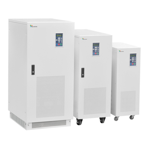
Tech Novitas Serius Series User manual

Serius UPS user manual
1-40K LF Online UPS

Preface
We thank you for selecting our Serius UPS and recommend you to read these
instructions carefully before installation and operation. Please keep this user manual
in a safe place for future references.
Applied Models: Serius 1/2/3/6/10KVA Single Phase in/ Single Phase out
Serius 10/15/20/30/40KVA 3 Phase in/ Single Phase out
Please read this manual carefully:
It provides important information, such as installation, operation, and maintenance to help you
increase your UPS performances. Follow the proper instructions can also extend your systems and
equipment lifetime.
Please keep this manual carefully:
It contains important safety instructions, important operational guidance, and relevant service
rules and documents.

Contents
1 General Introduction..................................................................................................................................1
1.1 Product introduction.......................................................................................................................1
1.2 UPS description..............................................................................................................................2
2.Install & Operation...............................................................................................................................13
2.1 Packing Case Inspection..............................................................................................................13
2.2 Installation location requirements:..............................................................................................13
2.3 Connecting to the mains.............................................................................................................. 13
2.4 External battery connection.........................................................................................................15
2.5 Boot-up testing............................................................................................................................. 21
2.6 Battery charging........................................................................................................................... 22
2.7 Loads connection......................................................................................................................... 22
2.8 Parallel redundancy instruction...................................................................................................23
2.9 Manual maintenance bypass announcements.............................................................................27
2.10 ECO Mode...............................................................................................................................28
3.Safety instructions................................................................................................................................ 28
4.Precautions and daily maintenance..................................................................................................... 29
4.1 Daily use.......................................................................................................................................29
4.2 Precautions................................................................................................................................... 29
4.3 Daily maintenance........................................................................................................................30
5.Network Monitor Management........................................................................................................... 31
5.1 Compatible operating system...................................................................................................... 31
5.2 Software monitoring features...................................................................................................... 31
5.3 Communication Interface (RS232)............................................................................................. 31
5.4 Software installation.................................................................................................................... 32
6.UPS status, fault and troubleshooting................................................................................................. 33

6.1 Statuses......................................................................................................................................... 33
6.2 Fault and Troubleshooting...........................................................................................................38
7. Serius Technical Specifications............................................................................................................. 40

Tech Novitas FZC U.A.E., Tech Novitas Corp. Ltd U.S.A, Tech Novitas ( Far East) Ltd, HK
www. technovitas.com, support@technovitas.com
1
1 General Introduction
1.1 Product introduction
Serius UPS is a type of double conversions true online UPS (Uninterruptible
Power Supply). It provides reliable, stable, and constant AC power for computer
equipment, telecommunication devices, precision equipment/instrument, and
network termination equipment (NTE). UPS systems protects all these devices from
losing data or information due to power outage, interruption or disruption to truly
and comprehensively solve power issues, such as power outage, power surge,
voltage sags, temporary overvoltage, temporary under voltage, frequency offset,
power disturbances, switching transients, and harmonic wave distortion.
◇Serius Online Low Frequency Series has the following 14 models:
1KVA Standard/Long-run type UPS System (Single Phase Input/ Single Phase
Output)
2KVA Standard/Long-run type UPS System (Single Phase Input/ Single Phase
Output)
3KVA Standard/Long-run type UPS System (Single Phase Input/ Single Phase
Output)
6KVA Standard/Long-run type UPS System (Single Phase Input/ Single Phase
Output)
10KVA Standard/Long-run type UPS System (Single Phase Input/ Single Phase
Output)
10KVA Long-run type UPS System (3 Phase Input/ Single Phase Output)
15KVA Long-run type UPS System (3 Phase Input/ Single Phase Output)
20KVA Long-run type UPS System (3 Phase Input/ Single Phase Output)
30KVA Long-run type UPS System (3 Phase Input/ Single Phase Output)
40KVA Long-run type UPS System (3 Phase Input/ Single Phase Output)
◇This Low Frequency Online UPS Series main features:
-- Fundamental Design Concept of power supply high reliability
-- Comprehensive functionalities and protections
-- Easy Maintenance Design

Tech Novitas FZC U.A.E., Tech Novitas Corp. Ltd U.S.A, Tech Novitas ( Far East) Ltd, HK
www. technovitas.com, support@technovitas.com
2
◇MAIN——Mains Input Power
Indicator. The Main is Okay.
◇BYPASS——Bypass Indicator.
The Loads will be supplied via
bypass.
◇INV.——Inverter Indicator.
Inverter is running normally when
this light is on.
◇BAT.——Battery Voltage Low
Indicator. When Battery Voltage is
near completion of discharging, this
indicator will be on.
◇OVERLOAD——Overload
Indicator. When UPS is overloaded,
this indicator will be turned on.
◇FAULT——Fault Indicator.
When UPS is failed, this indicator
will be turned on.
-- Intuitive LCD English/Chinese display and network managements
1.2 UPS description
1.2.1 UPS Front Panel

Tech Novitas FZC U.A.E., Tech Novitas Corp. Ltd U.S.A, Tech Novitas ( Far East) Ltd, HK
www. technovitas.com, support@technovitas.com
3
ON/OFF——Inverter On/OFF
Button. Inverter will be turned on
by pressing this button. UPS will
be shut down via press and hold
this button again for 6 seconds
DISPLAY ——LCD Screen
Select Button. Screen will be
scrolled by this button to select
different information.
LCD Screen — — It shows the
following UPS Status or
information:
Input Voltage and Frequency ,
Output Voltage and Frequency,
Battery or Charging Voltage,UPS
Output Capacity Percentage, and
Other UPS Status History Data.

Tech Novitas FZC U.A.E., Tech Novitas Corp. Ltd U.S.A, Tech Novitas ( Far East) Ltd, HK
www. technovitas.com, support@technovitas.com
4
1.2.2 1-3KVA Standard Type UPS Rear Panel Description
TAB
FUNCTION
①
COMM1/COMM2 for Parallel
②
UPS Output Socket
③
RS232 Communication Port
④
SNMP Card Socket
⑤
Mains Power Input Switch
⑥
Battery Switch
⑦
UPS Connection Terminals
Note: Technicians should distinguish Product Battery nominal voltage in order to
prevent errors.

Tech Novitas FZC U.A.E., Tech Novitas Corp. Ltd U.S.A, Tech Novitas ( Far East) Ltd, HK
www. technovitas.com, support@technovitas.com
5
1.2.3 1-3Kva Long-run Type UPS Rear Panel Description
TAB
FUNCTION
①
COMM1/COMM2 for Parallel
②
UPS Output Socket
③
RS232 Communication Port
④
SNMP Card Socket
⑤
Mains Power Input Switch
⑥
Battery Switch
⑦
UPS Connection Terminals
Note: Technicians should distinguish Product Battery nominal voltage in order
to prevent errors.

Tech Novitas FZC U.A.E., Tech Novitas Corp. Ltd U.S.A, Tech Novitas ( Far East) Ltd, HK
www. technovitas.com, support@technovitas.com
6
1.2.4 6KVA Standard Type Rear Panel Description
TAB
FUNCTION
①
SNMP Card Socket
②
RS232 Communication Port
③
COMM1/COMM2 for Parallel
④
Mains Power Input Switch
⑤
Battery Switch
⑥
UPS Connection Terminals

Tech Novitas FZC U.A.E., Tech Novitas Corp. Ltd U.S.A, Tech Novitas ( Far East) Ltd, HK
www. technovitas.com, support@technovitas.com
7
1.2.5 6KVA Long-run Type Rear Panel Description
TAB
FUNCTION
①
SNMP Card Socket
②
RS232 Communication Port
③
COMM1/COMM2 for Parallel
④
Mains Power Input Switch
⑤
Battery Switch
⑥
UPS Connection Terminals

Tech Novitas FZC U.A.E., Tech Novitas Corp. Ltd U.S.A, Tech Novitas ( Far East) Ltd, HK
www. technovitas.com, support@technovitas.com
8
1.2.6 10KVA Long-run Type Rear Panel Description
TAB
Name
FUNCTION
①
SNMP
SNMP card remote control socket
②
COMM1/COMM2
Parallel Redundancy Sockets
③
RS232
Available to communicate to PC for remote control
and communication
④
Manual Bypass
Only available for authorized technicians. Users
should not operate this Manual Maintenance Bypass
when UPS is working properly.
⑤
Output Switch
UPS Output Switch
⑥
Mains
Mains Input Switch
⑦
BAT.
Battery Switch
⑧
Bypass
Bypass Switch (only available for 20 KVA model)
⑨
Connecting Terminals
OUTPUT
UPS output terminals
EXT. BAT
External Battery Connection
Terminals
PARALLEL
Warm Backup Parallel port (Only for
warm backup Parallel systems)
INPUT
Mains Input Switch

Tech Novitas FZC U.A.E., Tech Novitas Corp. Ltd U.S.A, Tech Novitas ( Far East) Ltd, HK
www. technovitas.com, support@technovitas.com
9
1.2.7 10-20KVA 3 Phase Long-run type Rear Panel Description
TAB
Name
FUNCTION
①
SNMP
SNMP card remote control socket
②
COMM1/COMM2
Parallel Redundancy Sockets
③
RS232
Available to communicate to PC for remote control
and communication
④
Manual Bypass
Only available for authorized technicians. Users
should not operate this Manual Maintenance Bypass
when UPS is working properly.
⑤
Output Switch
UPS Output Switch
⑥
Mains
Mains Input Switch
⑦
BAT.
Battery Switch
⑧
Bypass
Bypass Switch (only available for 20 KVA model)
⑨
Connecting Terminals
OUTPUT
UPS output terminals
EXT. BAT
External Battery Connection
Terminals
PARALLEL
Warm Backup Parallel port (Only for
warm backup Parallel systems)
INPUT
Mains Input Switch

Tech Novitas FZC U.A.E., Tech Novitas Corp. Ltd U.S.A, Tech Novitas ( Far East) Ltd, HK
www. technovitas.com, support@technovitas.com
10
1.2.8 30-40KVA 3 Phase Long-run type Rear Panel Description
30KVA
Connection Terminals
40KVA
Connection Terminals

Tech Novitas FZC U.A.E., Tech Novitas Corp. Ltd U.S.A, Tech Novitas ( Far East) Ltd, HK
www. technovitas.com, support@technovitas.com
11
TAB
Name
FUNCTION
①
SNMP
SNMP card remote control socket
②
COMM1/COMM2
Parallel Redundancy Sockets
③
RS232
Available to communicate to PC for remote control
and communication
④
BATTERY
Battery Switch
⑤
Output Switch
Output: UPS Output Switch( only for parallel
redundancy)
⑥
Manual Bypass
Only available for authorized technicians. Users
should not operate this Manual Maintenance Bypass
when UPS is working properly.
⑦
BY-PASS
Static Bypass Switch
⑧
Mains
Mains Input Switch
⑨
Connecting Terminals
OUTPUT
UPS output terminals
EXT. BAT
External Battery Connection
Terminals
PARALLEL
Warm Backup Parallel port (Only for
warm backup Parallel systems)
INPUT
Mains Input Switch
⑩
Connection Tunnels
All UPS Connection Input/Output, battery wires can
passed into the machine through this hole

Tech Novitas FZC U.A.E., Tech Novitas Corp. Ltd U.S.A, Tech Novitas ( Far East) Ltd, HK
www. technovitas.com, support@technovitas.com
12
1.3.9 6KVA Long Run Type with ECO Mode Rear Panel Description
TAB
Name
Function
①
SNMP
SNMP card remote control socket
②
RS232
Available to communicate to PC for remote control
and communication
③
ECO Toggle
Switch
ECO/Normal Mode Switch
④
MAIN
Mains Input Switch
⑤
BATTERY
Battery Switch
⑥
OUTPUT Switch
UPS Output Switch
⑦
UPS Connection
Terminals
From the left to the right:Output(OUTPUT)、
Battery(BAT.)、Input(INPUT)
⑧
Connection
Tunnels
All UPS Connection Input/Output, battery wires
can passed into the machine through this hole

Tech Novitas FZC U.A.E., Tech Novitas Corp. Ltd U.S.A, Tech Novitas ( Far East) Ltd, HK
www. technovitas.com, support@technovitas.com
13
2.Install & Operation
2.1 Packing Case Inspection
◇Unpack the External Package carefully and check if there is any shipping
damage. In case of any sign of physical damages, please notify your local dealer
immediately.
◇Make sure the all the following accessories are in the package
Description
Quantity
Operating Manual
1
Warranty Card
1
Certification of Qualification
1
2.2 Installation location requirements:
To install the UPS system properly, please check the following conditions:
UPS must be installed on a flat location.
The distance between UPS housing and walls should be more than 10 cm.
Please keep UPS systems away from heat, and also avoid rain, direct sunlight.
Please keep UPS in a non-corrosive environment.
Maintain the operation circumstance in normal temperature and humidity.
Keep the UPS operation location clean and tidy.
2.3 Connecting to the mains
2.3.1 Should use proper air switch or distribution board to connect to the mains
because of big input current, do not use regular 10A or 15A socket or plug.
Tips:
In order to have easy and convenient future transportation, Please keep your
packaging materials inside the packaging box and save in a proper place.
If you find any missing accessories, please contact your local dealer
immediately.
Note: This UPS System is grade A UPS. It may cause radio interference in residential
environment. Users may be required to take appropriate actions in order to reduce interferences.

Tech Novitas FZC U.A.E., Tech Novitas Corp. Ltd U.S.A, Tech Novitas ( Far East) Ltd, HK
www. technovitas.com, support@technovitas.com
14
2.3.2 Serius Electrical Specifications
Model
Maximum
Input
current
Input Live
Wire Air
Switch
Input
wire
diameter
Maximum
Output
current
Output
wire
diameter
Max Battery
current
Battery wire
diameter
1K-S
11.5A
16A
>2.5mm2
4.5A
>2.5mm2
21.8A
>4mm2
1K-L
14.5A
32A
>4mm2
4.5A
>2.5mm2
21A
>4mm2
2K-S
19.0A
32A
>4mm2
9.1A
>2.5mm2
10.7A
>4mm2
2K-L
32.6A
40A
>4mm2
9.1A
>2.5mm2
22.6A
>6mm2
3K-S
27.4A
40A
>6mm2
13.6A
>2.5mm2
16.1A
>6mm2
3K-L
39.8A
40A
>6mm2
13.6A
>2.5mm2
34A
>6mm2
6K-S
45.8A
60A
>10mm2
27.3A
>4mm2
33.3A
>6mm2
6K-L
61.5A
80A
>10mm2
27.3A
>4mm2
31.7A
>6mm2
10K-L
90.5A
100A
>10mm2
45.5A
>6mm2
52.9A
>10mm2
10K-L-31
38.0A
50A/3P
>6mm2
45.5A
>6mm2
30.2A
>6mm2
15K-L-31
47.8A
60A/3P
>10mm2
68.2A
>12mm2
45.3A
>10mm2
20K-L-31
57.6A
63A/3P
>16mm2
90.9A
>16mm2
60.4A
>10mm2
30K-L-31
77.2A
80A/3P
>16mm2
136.4A
>25mm2
90.7A
>16mm2
40K-L-31
96.8A
100A/3P
>16mm2
181.9A
>25mm2
120.9A
>16mm2
Attention: “L” refers to long-run type models (Without internal battery), “S” refers to standard models (With internal
Battery), “31” refers to 3 Phase Input/ 1 Phase Ouput models.
Note:Models more than 10kva has manual maintenance bypass switch.

Tech Novitas FZC U.A.E., Tech Novitas Corp. Ltd U.S.A, Tech Novitas ( Far East) Ltd, HK
www. technovitas.com, support@technovitas.com
15
2.3.3 Installation requirement
◇Please make sure input power voltage before installation. Never connect 380V
input power to single phase UPS Systems.
◇Make sure that the three input wires "L" , " N" , " E" and "GND" are correctly
connected.
◇Please check all the electrical switches are on “OFF” positions before UPS
installations.
◇Series Installation Steps:
Open the cover of connection tunnels, connect the Input & Output wires to the
terminals inside the UPS cabinet correctly through the connection tunnels.
a. Connect wires in sequence of Input lines, Output lines, and Battery lines.
b. Wire Threads should be stabilized with proper crimping terminals to the
ports.
c. 1-3KVA can connect Loads directly to UPS output sockets, or connect
Loads to blocks on the output terminals.
2.4 External battery connection
2.4.1 External battery installation requirement
◇Various metal objects such as long screws, tools, wires on the installation site
should be away from batteries. Longer installation tools should be wrapped or
covered by insulated cloth to minimized exposed parts.
◇Batteries should be placed in the same direction, and connection blocks should
near the outer battery box in order to install easily.
◇Please follow the follow the battery connection instructions and UPS battery
Warning:
1. Please check the Mains power socket is the same type as the UPS input
socket before connection. Make sure the input wire ‘L” “N” ‘E” is correctly
connected.
2. Never install any switch on the “N” wire.
3. Please do not connect the Mains input wire/socket to the UPS output socket
or terminals; it will cause significant damages on UPS.

Tech Novitas FZC U.A.E., Tech Novitas Corp. Ltd U.S.A, Tech Novitas ( Far East) Ltd, HK
www. technovitas.com, support@technovitas.com
16
Caution:
All fastening bolt should be tightened with proper tools in order to prevent
overheat or ignition damage to the systems due to large current flow.
Battery short circuit or wrong connections will cause serious loss, such as battery
connection block or wires burn down, personal injury, battery damage, or even fire
hazard. Thus, operation should be performed by professional and qualified technicians.
Warning:
Please follow the instruction to use the proper amount of batteries while using
external battery connections.
requirements to connect batteries to UPS systems.
2.4.2 Battery Specification for External Connection
Model
Battery
nominal
Voltage
Actual Voltage
Charging
voltage
1K-L
12V×4 pcs
48Vdc
50Vdc
54.5Vdc
2K-L
12V×8 pcs
96Vdc
102.5Vdc
109Vdc
3K-L
6K-L
12V×16 pcs
192Vdc
205Vdc
218Vdc
10K-L
12V×16 pcs
192Vdc
205Vdc
218Vdc
10K-L-31
12V×30 pcs
360Vdc
384Vdc
408Vdc
15K-L-31
20K-L-31
30K-L-31
40K-L-31
2.4.3 Battery connection diagram
1 KVA Long-run Type Battery connection diagram
This manual suits for next models
15
Table of contents
Other Tech Novitas UPS manuals
Popular UPS manuals by other brands
Online UPS Specialist
Online UPS Specialist OPP Series operating manual
Vertiv
Vertiv Liebert GXT4-6000RTL630 Installer/user guide
Orvaldi
Orvaldi i600 LED USB user manual
Powerware
Powerware 9315 Installation & operation manual
Belkin
Belkin F6C1000-TW-RK user manual
extronics
extronics iUPS101 operating manual

Effekta
Effekta ME 1500 instruction manual
Aplus
Aplus 6KVA user manual
Legacy Power Conversion
Legacy Power Conversion HERYTAGE 2kVA 1.6kW User and installation manual
CyberPower
CyberPower UT400EG quick start guide

Steren
Steren NB-605 instruction manual
Atlantis Land
Atlantis Land OnePower Line Interactive UPS A03-P551 user guide
