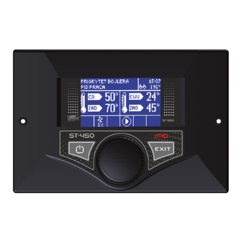
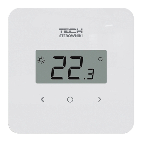
TECH ST-707 User manual


ST-707 Rotations Control
Declaration of Conformity No. 32/2010
Hereby, we declare under sole responsibility that the ST-707
230V 50Hz thermoregulator manufactured by TE H,
headquartered in Wieprz 1047A, 34-122 Wieprz, is compliant
with the Regulation by the Ministry of Economy. (Journal of Laws
Dz.U. 155 Item 1089) of July 21, 2007 implementing provisions
of the Low Voltage Directive (LVD) 2006/ 5/EC of January 16,
2007.
The ST-707 controller has been tested for electromagnetic
compatibility (EM ) with optimal loads applied.
For compliance assessment, harmonized standards were
used:
PN-EN 60730-2- :2006.
- 2 -

ST-707 Rotations Control
ATTENTION!
High voltage!
Make sure the regulator is disconnected from the
mains before working on the power supply (cable
connections, device installation, etc.)!
All connection works must only be carried out by
qualified electricians.
Before activating the controller, measure the motor
resetting efficiency and inspect wire insulation.
- 3 -


ST-707 Rotations Control
I. Description
Temperature regulator ST–707 is designed for H boilers equipped
with a wormwheel feeder. It controls the water circulation pump , the hot
usable water pump (HUW), the floor heating pump, the circulation pump,
the blow-in (fan) and the fuel feeder. This device may also cooperate
with two three-way or four-way valves, the room regulator ST-208, the
GSM module and the Ethernet module.
The advantage of this controller is its simplicity in operation. The
User makes all changes of parameters by means of the pulse
generator knob.
Another advantage is a large and transparent graphic display, where
the user can exactly see the current condition of the boiler's operation.
ontroller ST-
707
- 5 -
Pumps operation mode Time
Current CH temp.
Boiler operation phase
Boiler power
Temp. Of flue gas
Set CH temperature
Work of
CH pump
Work of
HCW pump
Work of
floor pump
Pump operation
of circulation pump
Wprk of
blow-in
Work of
the feeder

ST-707 Rotations Control
Rotations ontrol is a regulator with a continuous output signal, using
PID regulation algorithm. In this type of controller the blow-in power
is calculated on the basis of the measurement of the boiler temperature
and the temperature of flue gas measured on the boiler's outlet.
Operation of the fan proceeds on an ongoing basis and the blow-in power
depends directly on the measured boiler temperature, the temperature of
flue gas and the difference of these parameters from their preset values.
Stable maintenance of the set temperature without any unnecessary
adjustments and oscillations are the advantages of the zPID regulator.
Each controller should be set individually, for own needs, depending
on the type of fuel used for burning as well as the type of the boiler. The
TE H company will not be liable for any incorrect settings of the
controller.
When using this type of controller with a flue gas outlet sensor,
savings in fuel combustion may reach up to more than ten percent; The
outlet water temperature is very stable, which affects the longer life span
of the exchanger (boiler . Checking the temperature of flue gas at the
outlet from the boiler causes low emission of dusts and gases harmful for
the environment. Thermal energy from the flue gas is not wasted and
released to the chimney, but used for heating.
Below we present the results of tests conducted with the use of the Tech
controller with PID control:
and the same controller without PID control:
- 6 -

ST-707 Rotations Control
Any comments concerning the program should be reported to the
boiler's manufacturer.
Each controller should be set individually for personal needs,
depending on the type of fuel used for burning as well as the type of the
boiler. The TE H company shall not be liable for any incorrect settings of
the controller.
II. Functions of the regulator
This chapter describes the functions of the regulator, the method of
changing the settings as well as navigation in the menu which is made
using the pulse generator (knob). The boiler's operational parameters
are displayed on the main screen of the controller. The user selects the
operation mode and a number of settings of the boiler according to their
own needs.
After activation of the controller the name of the manufacturer of
the boiler as well as the version of the program are displayed on the
graphic display. A message with language selection appears after a few
seconds. In this function, the user may change the language version.
II.1. Basic definitions
Ignition – this cycle begins at the moment of activation in the menu of
the ignition function controller and when the choice is approved (the
following message will appear on the display: "PID: IGNITION" ) and
lasts until the time when the flue gas temperature reaches the value of at
least 60 o (preset ignition threshold), provided that this temperature
does not fall below this value for 30 seconds (preset ignition time).
Operation – after completion of ignition the regulator switches to the
operation cycle and the following message is shown on the display:
"PID: OPERATION". This is the basic functioning condition of the
- 7 -

ST-707 Rotations Control
regulator, in which the blow-in and fuel feeding proceeds automatically
according to the PID algorithm, oscillating around the temperature set by
the user. If the temperature unexpectedly rises by more than 5o above
the set value, the so-called supervision mode will be activated.
Supervision mode – this mode will activate automatically, if the
temperature in the operation cycle rises by more than 5o above the set
value. In such a case, in order to reduce the temperature of circulating
water, the controller will change the PID regulation to manual settings
(according to the parameters in the installer's menu) and the following
message will be shown on the display: "PID: SUPERVISION".
Extinguishment – if the flue gas temperature drops below 37o (preset
extinguishment threshold) and does not rise above this value for 30
seconds (preset extinguishment time), the regulator switches to the
extinguishment condition. In this state the blow-in and the feeder stop
working and the following message is shown on the display: "PID:
EXTINGUISHED".
II.2. Homepage
During normal operation of the regulator, the main page is visible on
the graphic display. Depending on the operation mode, one of the
following screens is displayed:
Pressing the knob of the pulse generator brings the user to the first
level menu. The first three menu options are shown on the display. Turn
the knob to move to subsequent options. Press the knob to select a given
function. Similar actions are made when changing parameters. To
introduce changes it is necessary to approve them by pressing the pulse
generator when the APPROVE message is shown. If the user does not
want to make any changes in a given function, they should press the
pulse generator when the CANCEL message is shown. To exit the menu
select the exit option.
II.3. Screen view
In this function, the user may choose one of the three main
- 8 -

ST-707 Rotations Control
thermoregulator operation screens. They are:
➢H screen (the current boiler operation mode is displayed),
➢valve 1 (displays the operational parameters of the first valve),
➢valve 2 (displays the operational parameters of the second valve).
➢manufacturer's screen - this view is unavailable to the user. This is
a special screen view only for the device's manufacturer.
NOTE
To make the views with valve parameters active, these valves must be
earlier accordingly installed and configured by the installer.
II.4. Ignition
The boiler can be easily kindled using this function. After initial
lighting up of a fire source, the user activates the automatic ignition
cycle. Thanks to selection of optimum parameters, the boiler will
smoothly switch to the operation mode using the PID function.
II.5. Set CH
This option is used to adjust the set boiler temperature. The user may
change the temperature range in the boiler from 45O to 80O . The set
H can also be changed directly from the main controller screen by
turning the pulse generator knob.
II.6. Set HUW
This option is used to adjust the set value of the hot utility water
temperature. The user may change this temperature in the range from
40O to 75O .
- 9 -

ST-707 Rotations Control
II.7. Manual mode
For the user's convenience, the regulator has been equipped with a
Manual operation module. In this function, each executive device (the
feeder, the blow-in, the H pump, the HUW pump, the circulation pump
and the floor pump) is activated and deactivated independently of the
others.
Pressing the pulse generator activates the engine of the chosen
device. This device remains activated until the pulse generator is
pressed again.
The blow-in power, where the user has the possibility to set any
rotational speed of the fan in manual operation, is additionally available.
II.8. Operation mode
In this function, the user selects one of four options of the boiler's
operation.
II.8.a) House heating
By choosing this option, the regulator switches to heating the house
only. The H pump starts to work above the pump activation threshold
(preset to 40O ). Below this temperature the pump stops working.
- 10 -

ST-707 Rotations Control
II.8.b) Reboiler priority
In this mode, the reboiler pump (HUW) is turned on first, until the set
temperature is reached. After reaching the set reboiler temperature, the
HUW pump shuts down and causes activation of the H pump. The H
pump operates constantly, until the moment when the temperature at
the reboiler drops below the set value. At that time, the H pump shuts
down and the HUW pump is activated
In this mode, operation of the fan and the feeder is limited to 62 degrees
in the boiler, since this prevents the boiler from overheating.
Note: The boiler should be equipped with return valves on the circuits
of the CH pump and the HUW pump. The valve mounted on the HUW
pump prevents hot water from being sucked out of the reboiler.
II.8.c) Parallel pumps
In this mode, both pumps work simultaneously above the pump
activation threshold temperature (preset to 40O ).
The H pump operates continuously and the HUW pump shuts down after
reaching the temperature set at the reboiler. The HUW pump will be re-
activated when the reboiler temperature drops below the set value (see
HUW hysteresis in the installer's menu).
NOTE: In this mode, one should install a three-way valve or another
mixing valve causing maintenance of a different temperature in the
reboiler and of a different in the house.
II.8.d)Summer mode
After activation of this function, only the HUW pump, whose task is
additional heating of the reboiler, operates. This pump is activated above
- 11 -

ST-707 Rotations Control
the set activation threshold (see the pump activation temperature
function) and operates until the set temperature is reached. The pump
will be activated again when the temperature drops below the set value
and the set hysteresis. In the summer mode, one sets only the set
temperature in the boiler which additionally heats the water in the
reboiler (the set boiler temperature is at the same time the set reboiler
temperature).
II. . Weekly control
The function is used to programme daily changes in the boiler
temperature. The preset temperature deviations are within the range of +/-
100.
Step 1:
The user needs to set current time and date first (Installer menu > Clock .
Step 2:
The user sets temperature values for individual days of the week (Set mode 1):
Monday– Sunday
Select specific hours and required deviations from the preset temperature (how
many degrees the temperature should rise or drop) for each day of the week.
Additionally, the preset values can be copied to facilitate the operation.
Example
Monday
preset: 3 00 , temp. -100 (temperature change– 100)
preset: 4 00 , temp. -100 (temperature change – 100)
preset: 5 00 , temp. -100 (temperature change – 100)
In such a case, if the temperature preset on the boiler is 60º , it will drop
10º to 50º between 3 a.m. and 6 a.m. on Monday.
As an alternative to the temperatures being preset separately for
individual days, the temperatures can also be set collectively, in the second
mode, for the working days (from Monday to Friday) and the weekend
(Saturday and Sunday) separately - Set mode 2.
Monday - Friday; Saturday - Sunday
Similarly to the previous mode it is necessary to select specific times and
required deviations from the temperature preset for the working days (Monday -
Friday) and the weekend (Saturday, Sunday).
- 12 -

ST-707 Rotations Control
Example
Monday - Friday
preset: 3 00 , temp. -100 (temperature change – 100)
preset: 4 00 , temp. -100 (temperature change – 100)
preset: 5 00 , temp. -100 (temperature change – 100)
Saturday - Sunday
preset: 16 00 , temp. 50 (temperature change +50)
preset: 17 00 , temp. 50 (temperature change +50)
preset: 18 00 , temp. 50 (temperature change +50)
In this case, if the preset boiler temperature is 60º , the temperature will drop
10º to 50º between 3 a.m. and 6 a.m. on each day from Monday to Friday.
However, the temperature will rise 5º to 65º during weekend (Saturday,
Sunday) between 4 p.m. and 7 p.m.
Step 3:
The user enables one of two preset modes (Mode1, Mode2) or disables the
weekly control option.
Once the mode is enabled the value of the deviation currently set is displayed
on the main page of the controller next to the preset central heating system
temperature. This, additionally, indicates that the weekly control is active.
Data deletion function is a simple method to remove all previously
saved weekly programme settings to enter new settings.
II.10. Fuel granulation
This option allows to choose the main fuel granulation, with which the
boiler is fired .
II.11. Installer's menu
The functions in the installer's menu should be set by the person
installing the boiler or by the manufacturer's service.
II.12.a) Fan coefficient
This function is used to control the fan power. The control is based on shifting
the fan performance curve up or down. If the blowing rate in the whole control
range is too low/high, the coefficient should be increased/decreased accordingly
to ensure proper efficiency of the fan operation.
Malfunctioning of the blowing system is most frequently caused by relatively
large differences between voltages supplied to individual units, which has a
- 13 -

ST-707 Rotations Control
significant impact on the fan operation.
II.12.b) Power coefficient
Fuel feeding coefficient is intended to optimize the feeder operation so as to
ensure that fuel is fed to the furnace in proper quantities. This function allows
setting the percentage increase or decrease of fuel being supplied.
Once the proper fuel size is selected in the main menu it is possible, by using
the coefficient, to adapt precisely the fuel quantity to be fed by the feeder to
the furnace.
II.12.c) Room regulator
ontroller ST-707 Rotations ontrol can be connected to room
regulator ST-208 (additional option). This regulator is an extended
device, allowing to control several parameters at the same time. The user
has the opportunity to change the set temperature of the boiler and the
mixing valves. An additional advantage of the device is the weekly
heating program and the parental lock protecting against unwanted
changes in the settings.
After activation of the TECH Regulator options on the main screen
of the controller at the top part of the display, the letter "P" will appear.
Flashing letter "P" means the room is underheated; when the set
temperature is reached in the flat, "P" will glow permanently.
NOTE: No external voltage may be connected to the output of the room
regulator.
II.12.d) Valve 1 and 2
NOTE ontrolling the valve is possible only after purchasing an
additional ST-61 control module and connecting it to the controller, which
is not included to the room regulator as a standard feature. Two ST-61
modules should be connected to control two valves.
This option is used to set the operation of the mixing valve. To make
sure that the valve works properly in accordance with the user's
- 14 -

ST-707 Rotations Control
expectation, is should be registered by entering the module number
(this is number of the valve in accordance with the documentation) and
then several parameters should be set.
1. Switch on
This feature allows you to temporarily make the valve inactive.
2. Temperature control
In this function, the opening time of the valve is set - in other
words, how long it takes the valve to open to the value of 100%. This
time should be selected in accordance with the owned valve servomotor
(stated on the rating plate).
3. Opening time
In this function, the time of full valve opening is set, in other words,
how long it takes the valve to open to the value of 100%. This time
should be selected according to the owned valve servomotor (stated on
the rating plate).
4. Unit step
In this function, the unit percentage valve opening stroke, that is the
minimum percent of opening or closing the valve is expected to execute,
is set.
- 15 -

ST-707 Rotations Control
5. Minimum opening
In this function, the minimum value of the valve opening is set.
Below this value, the mixing valve will not close any further.
6. Valve type
With the use of this option, the user selects the type of the valve:
H or floor.
7. Weather-based control
To activate the weather function, external sensor should be placed in
the place which is not isolated and not exposed to atmospheric impacts.
After installation and connection, a sensor should have the function of
Weather sensor activated in a controller menu.
To make sure that the valve works correctly, the set temperature is
set (behind the valve) for three intermediate external temperatures:
Set temperature threshold 1 -20 o
Set temperature threshold 2 0o
Set temperature threshold 3 + 20o
Below, an example for the valve set as Type> floor:
Heating curve – this is a curve, according to which the preset controller
temperature is determined, on the basis of external temperature. In our
controller, this curve is constructed on the basis of three points of set
temperatures for the respective external temperatures. Set temperatures
- 16 -

ST-707 Rotations Control
must be determined for external temperatures of - 20º , 0º and 20º .
The more points constructing the curve, the greater its accuracy,
which allows its flexible shaping. In our case three points, seem a very
good compromise between the accuracy and the ease in setting the
course of this curve.
Where, in our controller:
XA=20˚
XB =0º ,
X=20º ,
YA, YB , Y – set for external temperatures XA, XB , X ,
O1 – operation of increasing the set
[Temperatura zewnętrzna – External temperature; Temperatura zadana –
Set temperature]
Increasing/reduction the set temperature consists in increasing /
reducing the current set temperature visible on the main screen. Such a
change causes automatic shift of the heating curve by the changed value.
This shift consists in adding to parameters YA, YB , Y temperature change
O1.
Below there are formulas for calculating the current set temperature:
where:
X – current temperature outside,
Y – calculated set temperature
- 17 -

ST-707 Rotations Control
8. Return protection
This function permits setting the boiler protection against too cool
water returning from the main circulation, which could cause low-
temperature boiler corrosion. The return protection operates in the way
that when the temperature is too low, the valve is closed, until the short
circulation of the boiler reaches the appropriate temperature. This
function also protects the boiler against dangerously high temperature of
return in order to prevent boiling of water.
. Additional sensors
When two mixing valves are used and you select this function you will be
able to select the sensors from which temperature data are to be retrieved for a
valve (for return and outside temperature sensors). Temperatures can be
retrieved from the sensors of the valve being set (Own) or as per the controller
sensors (Main controller).
10.Pump activation temperature
This option is used to set H and HUW pump activation temperature (this is the
temperature measured on the boiler). Both pumps do not operate below the set
temperature and above this temperature they are activated, but operate
depending on the operation mode (see: pump operation mode).
11. Changing the set valve
This setting is used to set the circuit temperature to be maintained by the
mixing valve. This is the main temperature based on which the room
thermostat reduction function is to be run (see Section III.a.10). The room
thermostat reduction function is set separately for the H system (setting in the
user menu) and separately for each of the valves.
12. Room temperature difference
This function is active only when the unit is operated with a (standard or TE H)
room thermostat. When the room thermostat reaches the desired temperature
in the house/flat (reports heated up condition), the valve will close to such an
extent so that the temperature downstream of the valve drops by the <room
thermostat reduction> temperature.
- 18 -

ST-707 Rotations Control
NOTE: If the installation includes a TECH room thermostat with RS
communication (four-wire cable , you may choose an option providing dynamic
control for the mixing valve
13. Factory settings
This parameter allows you to restore the mixing valve settings saved by the
manufacturer. By restoring the factory settings you will not change the valve
type setting (central heating or floor type).
14. Valve removal
This function is used for a complete removal of the valve from the
controller memory. Valve removal is used e.g. at disassembling the valve
or module replacement (re-registration of a new module is necessary).
II.12.e) GSM module
NOTE Controlling of this type is possible after purchasing and connecting,
to the controller, the additional control module ST-65 which is not attached to
the regulator as a standard feature.
The GSM module is an optional device cooperating with the boiler
controller, enabling remote control of the boiler operation with the use of a
mobile phone. The User is notified with a text message on each alert of the
boiler controller, and by sending an appropriate text message at any time, he
or she receives a return message with the information on the current
temperature of all sensors. After entering an authentication code it is also
possible to remotely change the set temperatures.
The GSM module can also operate independently from the boiler
controller. It has two inputs with temperature sensors, single contact input for
use in any configuration (detecting short circuit/opening of contacts) and one
controlled output (e.g. possibility to connect additional contactor to control any
electrical circuit).
When any temperature sensor reaches the preset deactivation
temperature, maximum or minimum, the module will automatically send a text
message with such information. It is similar in the case of a short-circuit or
- 19 -

ST-707 Rotations Control
opening of contact input, which may be used e.g. for simple protection of
property.
If ST-707 controller is equipped with an additional GSM module, in order to
activate this device, it is required to start the activated option (MENU> Installer
menu> GSM module> Activated).
II.12.f) Internet module
NOTE: Controlling of this type is possible after purchasing and connecting, to
the controller, the additional control module ST -500 which is not attached to
the regulator as a standard feature.
The Internet module is a device enabling remote control of the boiler over
the Internet or local network . On the home computer screen the user controls
the condition of all boiler system devices and the operation of each device is
presented in the animated form.
Apart from the possibility to view the temperature of every sensor, the
user has the possibility of introducing changes of the set temperatures for both
the pumps and the mixing valves.
After activating the Internet module and selecting the DH P option, the
controller will automatically download such parameters from the local network
as: IP address, IP Mask, Gateway address and DNS Address. In the case of any
problems with downloading network parameters of the existing network, there
is a possibility of setting these parameters manually. The method of obtaining
local network parameters has been described in the instructions for the Internet
module.
The function Reset module password may be used when the User, on the
login page, has changed the factory user's password to his or her password.
When a new password is lost, it is possible to return to the factory password
after resetting the module password.
II.12.g)Pumps switch on temperature
Use this option to set the activation temperature of the pumps. The pumps
will start to run above the pre-set temperature. The pumps will be switched off
when the boiler temperature drops below the activation temperature (minus a
hysteresis of 2° ).
- 20 -
Table of contents
Other TECH Thermostat manuals
TECH
TECH EU-R-8b Plus User manual
TECH
TECH Sinum R-S3 User manual
TECH
TECH EU-R-8s Plus User manual
TECH
TECH EU-290 v1 User manual
TECH
TECH ST-280 User manual
TECH
TECH ST-29 v1 User manual

TECH
TECH ST-37 Assembly instructions
TECH
TECH Sinum R-S2 User manual
TECH
TECH EU-F-8z User manual
TECH
TECH EU-R-8PZ Plus User manual
