TECHCON SYSTEMS TS6500CIM User manual
Techcon Systems
TS6500CIM
Automatic Techkit Mixer
User Guide
English, German, French

2
CONTENTS
Page Number
1. Safety……………………………………………………….………..………..
2. Unpacking and Inspection…………………………………….……..……….
3. Description …………………………………………………….…………….
4. Symbol Definitions……………………………………………..….……………
5. Emergency Stop………………………………………………………………
6. Specifications……………………………………………………..…………
7. Features and Function……………………………………………………………
7.1 Features………………………………………………..……………
7.2 Operation Function …………………………………….…..…….…..
8. Setup and Operation……………………………………………………….
8.1 Voltage Selection and Fuse Replacement ………………………..
8.2 Plastic Tray Installation……….………………………….…….……
8.3 Spindle and Extension Installation…………………………………………
8.4 Turn on the Unit…………….…………………………….…………….
8.5 Cartridge Kit Preparation….………………………………….…….……..
8.6 Loading the Cartridge Kit……………………………………….…..
8.7 Mix Cycle Program Setup……..…………………………………...
8.8 Start the Unit………...……………………………………..…………
8.9 Unloading the Cartridge Kit…….……………………………………..
8.10 Manual Mode………………………………………………………
9. Speed Control…………………………………………………………………
9.1 For Main Cylinder…………………………..………………………
9.2 For Injection Rod………………………………………………..……
10. Troubleshooting………………………………………………………………
11. Program Selection………………………………………………………………
12. Cycle Counter Reset………..…………………………………………….….
13. Cartridge Holder Installation………………………..…………….…………..
14. Maintenance…………………………………………………………………
15. Warranty…….…………………………………………………………………..
16. Appendix 16.1 Spare Parts List……………..……….……….……………..
16.2 Techkit Part Number Chart……………..……….……….
3
3
4
4
4
5
6-10
6-8
9-10
11-17
11
12
12-13
13-14
14
15
16
16
16
16-17
17
17
17
18
19
19
19-20
21
21
22-24
25

3
1. SAFETY
Intended Use:
WARNING: Use of this equipment in ways other than those described in this
User Guide may result in injury to persons or damage to property. Use this
equipment only as described in this User Guide.
OK International cannot be responsible for injuries or damages resulting from
unintended applications of its equipment. Unintended uses may result form taking
the following actions:
•Making changes to equipment that has not been recommended in the User
Guide
•Using incompatible or damaged replacement parts. Using unapproved
accessories or auxiliary equipment
Safety Precautions:
•Do not operate this unit in excess of maximum ratings/settings
•Always wear appropriate personal protective clothing or apparel
•Care must be taken to prevent the ingress of corrosive or flammable fluid back
into the Refer to Material Safety Data Sheet for proper handling and safety
precautions
•Do not smoke or use open flame when flammable materials are being dispensed
•This equipment is for indoor use only.
2. UNPACKING AND INSPECTION:
Carefully open the crate and examine all items contained inside.
The following items should be included:
1. TS6500CIM Main Assembly –in the main compartment
2. Accessory parts –packaged in a box and stored in an accessory
compartment, which include:
Description (Quantity)
Description (Quantity)
Cartridge Holder Assembly (1)
Air Filter (1)
Plunger Assembly (1)
Wrench holder (1)
Tool Holder (1)
User Guide (1)
Plunger Holder (1)
Air Hose (1)
Spare O-ring (5)
Fuse (1)
Spindle Assembly (1)
Power Cord (1)
Spindle Extension (1)
Screws (8)

4
3. DESCRIPTION
The TS6500CIM Series Automatic Techkit Mixer provides complete automatic
mixing of two-component materials packaged in cartridge.ts.niversal power
supply.
Equipped with a universal power supply, the TS6500 mixer is immediately usable
anywhere in the world. The automatic fluid sensing device makes it very simple
for the operator to install and setup all cartridge kit sizes. The user friendly
firmware provides up to 10 programmable mixing sequences with storage for 10
profiles.
The TS6500CIM Series is available in five versions:
•TS6500CIM-6 for 2.5oz. (60ml), 6.0oz. (160ml) and 8.0oz. (220ml) Kit
•TS6500CIM-20 for 20oz. (550ml) Kit
•TS6500CIM-RS-6 for 6.0oz. (160ml) Kit with reduced motor speed (116 RPM)
•TS6500CIM-SMR-6 for 6.0oz. (160ml) Kit with steel mix rod
•TS6500CIM-SMR-20 for 20oz. (550ml) Kit with steel mix rod
The following conversion kits are also available for your conveniences:
•CK6500-6 Conversion kit for 2.5 (60ml), 6.0 (160ml) and 8.0 oz. (220ml) Kit
•CK6500-10 Conversion kit for 1/10 gal.(310ml) Kit
•CK6500-20 Conversion kit for 20 oz.(550ml) Kit
4. SYMBOL DEFINITIONS
5. EMERGENCY STOP
In case of an emergency, the mixing operation can be stopped at any time by
pressing the EMERGENCY STOP BUTTON, (Fig 2, 10). After the problems have
been fixed, the machine can be restarted by pulling and turning the emergency
button counter clockwise. The mix cycle will start from the beginning.

5
6. SPECIFICATIONS
Size
16.5'' (420mm) X 16.8'' (426mm) X 38.2'' (970mm)
Weight
80lbs (36kg)
Input Voltage
120/230 VAC, 50/60 Hz
Rated Fuse
2A @ 120 VAC / 230 VAC
Motor Speed
139 RPM
Motor Torque
42 in-lb (4.7 Nm)
Indoor Use
Altitude up to 6,562ft (2,000m)
Operating Temperature
32˚F to 122˚F (0˚C to 50˚C)
Storage Temperature
-10˚C to 60˚C (14˚F to 140˚F)
Max. Relative Humidity
80% for temperature up to 87.8˚F ( 31˚C)
Decreasing linearly to 50% relative humility at
104˚F (40˚C)
Air Input
50 to 100 psi (3.5 –6.9 bar)
Display
LCD 20 X 4 display segments
Figure 1.0 Outside Dimensions
6
7. FEATURES AND FUNCTIONS
7.1 Features
ITEM
DESCRIPTION
ITEM
DESCRIPTION
1
Plunger Bracket
9
Air Regulator
2
Cartridge Holder
10
E-Stop Button
3
Guide Block
11
LCD Display
4
Plunger Air Inlet
12
Safety Cover
5
Pressure Relief Valve
13
Handle
6
Drive Spindle with Injection Rod
14
Fluid Level Sensor
7
Start Buttons
15
Fluid Level Sensor Magnet
8
Control Buttons
16
Plunger
Figure 2.0 Front View
7
ITEM
DESCRIPTION
ITEM
DESCRIPTION
17
Flow Control, Injection Rod
21
Air Filter
18
Flow Control, Main Cylinder
22
Wrench
19
Voltage Select Switch
23
Accessories Bracket
20
Power Input Socket with Fuse box
24
Cartridge Holder Bracket
Figure 3.0 Back View

8
Figure 4.0 Buttons and Screen Identification
SAFE TO
RUN
TOTAL
MIX
TIME
CYCLE
COUNTER
MIX
CYCLE
SET
PROGRAM
MODE
PRESSURE
POWER/(-)
CYCLE
BUTTON
MODE/(+)
CYCLE
BUTTON
SETUP/SAVE
BUTTON
Figure 5.0 Setup Screen Identification

9
7.2 Operation Function
DESCRIPTION
FUNCTION
1
Plunger Bracket
•Holds plunger assembly when not in use
2
Cartridge Holder
•Holds cartridge kit
•Operates with the plunger assembly and guide block
to drive the cartridge up and down for mixing
3
Guide Block
•Operates with the plunger assembly and cartridge
holder to drive the cartridge up and down for mixing
4
Air Plunger Inlet
•Provides air to plunger
5
Pressure Relief valve
•Relief plunger pressure when door is opened
6
Drive Spindle with
Injection Rod
•Rotates mix rods during mix cycle
•Injects the hardener into the resin
7
Start Buttons (Green)
•Starts the unit
•Press green buttons simultaneously to start
8
Control Buttons
•Input buttons (see Fig. 4.0 and Fig. 5.0)
9
Air Regulator
•Regulates the air pressure to the unit
10
Emergency Stop
button (Red)
•Stops the Unit in an Emergency
•Press to Engage
•“E-Stop!’‘ will be displayed,
•To reset, rotate the E-Stop knob a quarter turn
clockwise
11
LCD Display
•Displays unit status, operation and error messages.
12
Protective (Safety)
Cover
•Protects operators when machine is in use
13
Plunger Disk
•Part of Plunger Assembly
14
Fluid Level Sensor
•Senses the fluid level at the top of the cartridge

10
15
Fluid Level Magnet
•Works with fluid level sensor
16
Plunger Assembly
•Locks cartridge in place
•Applies steady pressure to prevent air entrapment
17
Flow Control; Main
Cylinder
•Controls the speed of the main cylinder
•Rotate the flow control screw clockwise to increase
the speed.
•Rotate the flow control screw counterclockwise to
decrease the speed
18
Flow Control;
Injection Rod
•Controls the speed of the injection rod
•Rotate the flow control screw clockwise to increase
the speed.
•Rotate the flow control screw counterclockwise to
decrease the speed
19
Voltage Select
Switch
•Select 115V or 230V
20
Power Input Socket
with Fuse Box
•Input power connection
21
Air Filter
•Provides air filtration
22
Wrench
•Used to install the air filter assembly and drive
spindle assembly
23
Accessories Bracket
•To hold wrench or other accessories
24
Cartridge Holder
Bracket
•To hold extra cartridge holder
11
8. SETUP AND OPERATION
WARNING: This unit is equipped with a voltage selector switch. Please check to
make sure the voltage selector is set to match the voltage input.
8.1 Voltage Selection and Fuse Replacement
1. Select the proper voltage by sliding the voltage switch up or down
Fuse Replacement: The unit is shipped with the fuse installed. If fuse
needs to be replaced please follow instructions below
2. Remove the fuse holder by using a flat head screw driver to pry it open.
3. Insert correct fuse into the fuse box, refer to table above
4. Re-install the fuse holder into the unit
Voltage Range
Voltage Setting
Fuse Rating
100V –120V
115V
2 Amp, Type F
220V –240V
230V
2 Amp, Type F
Figure 6.0 Fuse Installation
FUSE
HOLDER
VOLTAGE
SELECTOR
SWITCH
SCREW
DRIVER
FUSE
HOLDER
FUSE HOLDER
WITH FUSE
INSTALLED
FUSE
12
8.2 Plastic Tray Installation
The unit is shipped with a plastic tray to prevent any spilled material
migrating into the main control panel. Make sure to install the plastic tray
onto the base plate by aligning the four tabs into the base plate holes.
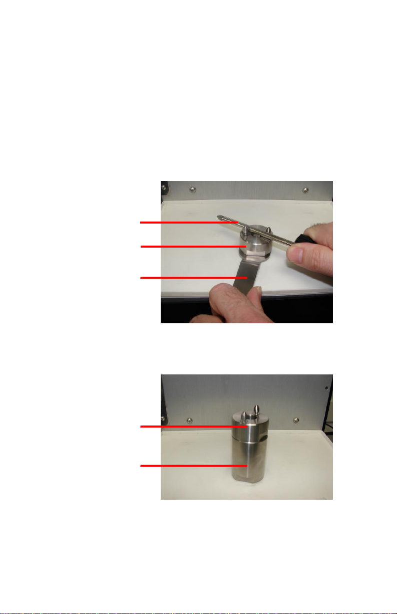
8.3 Spindle and Spindle Extension Installation
The unit is shipped with the spindle uninstalled. To install the spindle, align
it on the motor drive shaft then turn in clockwise direction.
Note: The spindle is designed to mix cartridge kits with 8'' (203mm) mix
rod. To mix cartridge kits with 6'' (152mm) mix rod, the spindle extension
needs to be installed. Follow the instructions below to install the spindle
extension:
Figure 7.0. Remove Spindle Assembly
Figure 8.0. Spindle Assembly with Extension
SCREW
DRIVER
SPINDLE
ASSEMBLY
WRENCH
SPINDLE
ASSEMBLY
SPINDLE
EXTENSION
13
Figure 9.0 Air and Power Connection
1. Place the wrench on the motor shaft (beneath the spindle).
2. Place a screw driver between the two locking pins of the spindle.
3. Hold the wrench and turn the screw driver counter clockwise to unscrew the
spindle assembly.
4. Remove the spindle assembly from the motor shaft.
5. Install the spindle extension on the motor shaft by turning it clockwise.
6. Install the spindle assembly on the spindle extension by turning it
clockwise.
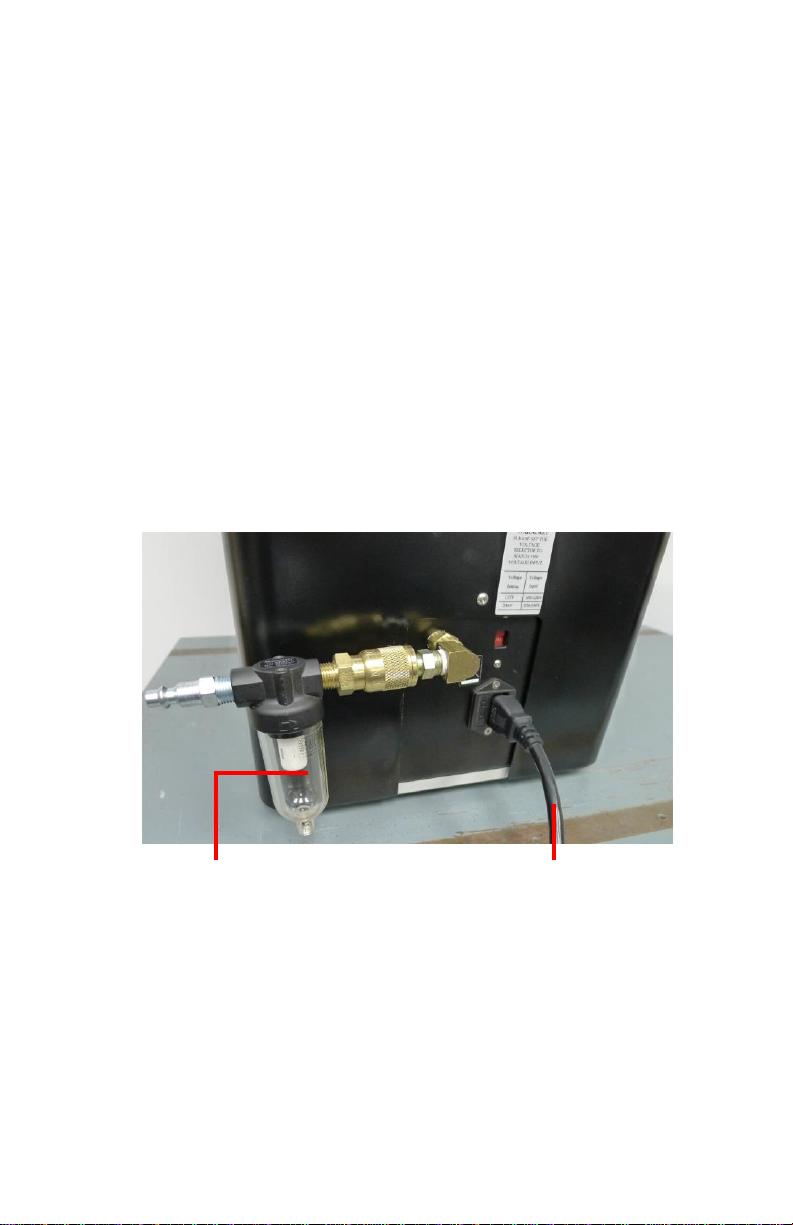
8.4 Turn On the Unit
Caution: Make sure the correct fuse has been installed and the correct
voltage has been set. Refer to section 8.1 for instructions.
1. Insert the power cord to the power socket (Fig. 3, 20).
2. Connect the air filter assembly to the air inlet (Fig. 3, 21).
3. Connect the air hose to the air filter assembly .
Caution: The air filter assembly (7091-9080), supplied with the unit, must be
installed to ensure proper air filtration.
4. Set the air Pressure to 80 psi (5.5 bar) minimum.
•Rotate the air pressure regulator knob (Fig. 2, 9) clockwise to increase the
air pressure.
•Rotate the air pressure regulator knob counterclockwise to decrease the air
pressure.
AIR FILTER
POWER CORD

14
5. The desired air pressure will be displayed on the screen.
6. Turn on the unit by pressing the power button (Fig. 4). The cartridge holder
should move up to home position. If it does not move up, please check
pressure connection.
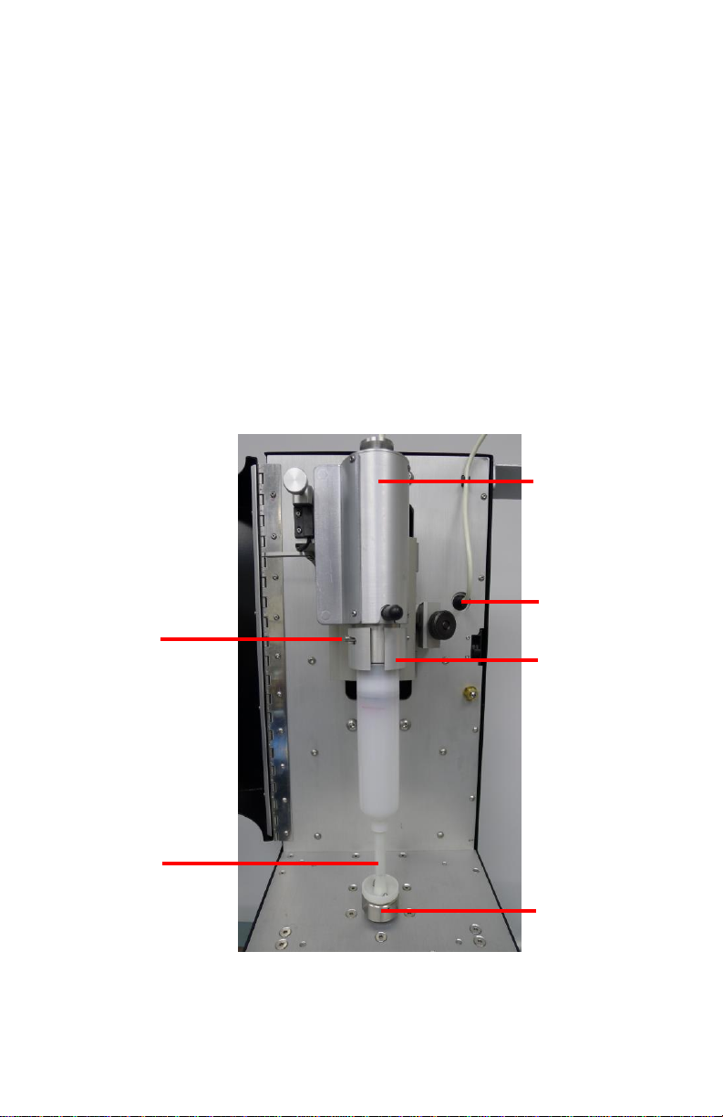
8.5 Cartridge Kit Preparation
Injection Kit:
The TS6500 Mixer has an automatic injection device that will inject the hardener
into the catalyst before the mixing cycle starts. However, the valve in the mix rod
needs to be opened before placing the kit in the machine. Follow the below
instructions to open the valve.
1. Insert the ram rod into the mix rod.
2. Push the ram rod to force the valve open.
3. Follow the instructions in section 8.7 to mix the injection kit.
Barrier Kit
1. Remove barrier tape from the kit.
2. Pull the mix rod down to the fullest extend to remove the foil from the
dasher.
3. Follow instructions in section 8.7 to mix the barrier kit
Figure 10.0 Injection Kit
Figure 11.0 Barrier Kit
MIX ROD
VALVE
MIX ROD
BARRIER TAPE
FOIL
DASHER
15
8.6 Loading the Cartridge Kit
Note: The unit is setup to mix cartridge kit with 8'' (203mm) mix rod. To
mix cartridge kit with 6'' (152mm) mix rod, the spindle extension needs to
be installed. Refer to section 8.3 for instructions.
1. Open the safety cover (Fig. 2.0, 12).
2. Load the cartridge kit into the cartridge holder (Fig. 2.0, 2).
3. Pull the mix rod to the fullest extend then align the two through holes of the
rod to the drive spindle (Fig. 2.0, 6).
4. Turn the cartridge kit lightly in clockwise direction to lock it to the spindle.
5. Insert the plunger assembly (Fig. 2.0,16) into the cartridge holder with the
plunger correctly seated inside the cartridge.
6. Align the dowel pins of the plunger assembly with the bayonet slots in the
cartridge holder and turn counterclockwise until it locked in.
7. Connect the air hose into the plunger air inlet (Fig. 2.0, 4).
8. Close the safety cover.
Figure 12.0 Loading the Cartridge Kit
LOCKING DOWEL
PINS
MIX ROD
PLUNGER
ASSEMBLY
PLUNGER
AIR INLET
CARTRIDGE
HOLDER
DRIVE
SPINDLE

16
8.7 Mix Cycle Program Setup
Refer to Fig. 4.0.
1. Press the Mode button to select Auto mode.
2. Press and hold the Setup button for 3 seconds to enter setup screen.
3. Press the Setup button to move the cursor to the “CYCLE’‘ indicator.
4. Press the (+) and (-) button to set number of mix cycles required.
5. If a delay time is required, press the Setup button to move the cursor to the
“DELAY’‘ indicator then press the (+) and (-) button to adjust delay time,
for up stroke and down stroke. (Fig. 5.0 D: Down / U: Up)
6. Press and hold the Setup button for 3 seconds to save data. The unit is now
ready to run.
8.8 Start The Unit
1. Ensure the unit is in the Automatic Mode and the desired profile has been
selected.
2. Press and release the Start buttons (Green) (Fig 2.0, 7) simultaneously.
3. The unit will run the selected profile. The cycle count and elapsed time will
be displayed on the LED screen.
8.9 Unloading The Cartridge Kit
1. The machine will automatically stop once the mixing cycles are completed.
2. Open the protective cover (Fig. 2.0, 12).
3. Remove the retaining collar plunger assembly (Fig. 2.0, 16) by turning it
clockwise.
4. Place the retaining collar plunger assembly on the side bracket (Fig. 2.0, 1).
5. Turn the cartridge kit clockwise to remove it from the drive spindle.
6. Pull the cartridge kit out of the cartridge holder.
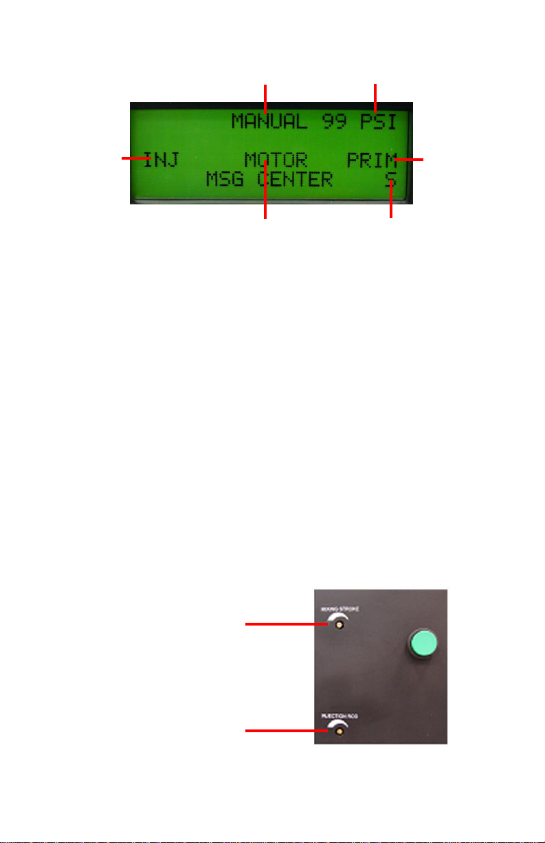
8.10 Manual Mode
While in the manual mode, the injection rod, main cylinder and drive spindle
motor may be controlled independently. Note: while in manual mode any errors
will not halt the operation of the motors. Refer to Fig. 13.0.
1. Press and hold the Mode button for 3 seconds to select Manual mode
2. Press the Power (-) button to activate the injection rod (the injection rod
will move up).
3. Press the Mode button (+) to activate the motor (the drive spindle will
rotate).
4. Press the Setup button () to activate the main cylinder (the cartridge
holder will move up and down).
17
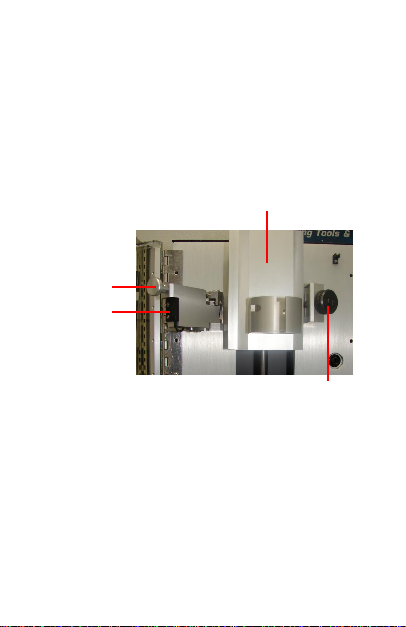
9. SPEED CONTROL
9.1 For main cylinder
The main air cylinder drives cartridge kit up and down. The stroke speed of
the main air cylinder can be adjusted by rotating the flow control screw
(Fig. 14.0) counter clockwise to increase the speed and clockwise to
decrease the speed.
9.2 For injection rod
The injection rod air cylinder drives the injection rod up and down. The
injection speed can be adjusted by rotating the flow control screw (Fig.
14.0) counterclockwise to increase the speed and clockwise to decrease the
speed.
Note: For TS6500CIM-SMR-6 and TS6500CIM-SMR-20 models, the
injection rod flow control is shut-off from the factory. To re-activate
the injection rod, slowly turn the flow control screw counter-clockwise
until the desired speed is achieved.
Figure 13.0 Manual Mode Screen
ACTIVATE
INJECTION
MODE
PRESSURE
ACTIVATE
MIX CYCLE
SAFE TO RUN
ACTIVATE
MOTOR
MAIN AIR CYLINDER
FLOW CONTROL
INJECTION ROD FLOW
CONTROL
Figure 14.0 Flow Control

18
10. TROUBLESHOOTING
PROBLEM
POSSIBLE CAUSE
CORRECTION
Unit fails to start
•No power input
•Emergency button is
pressed
•Safety door is not
fully closed
•Check power
connections
•Release Emergency stop
button
•Close safety door
LCD does not light
•No power input
•Check power
connections
•Check Fuse
•Turn on power
Air Cylinder does not
move
•Insufficient air
pressure
•Air hoses not
plugged in
•Regulator defective
•Increase air pressure to
80 psi (5.5 bar)
•Check air connection
•Replace regulator
The hardener is not
completely injected
•Air cylinder is
damaged
•Replace air cylinder
The injection rod does
not retract
•Injection rod is dirty
•Injection rod is bent
•Clean rod
•Replace rod
Material is not
completely mixed
•Not enough mixing
cycle
•Insufficient air
pressure
•Increase number of
cycles
•Increase air pressure to
80 psi
Cartridge holder is not
in “Home’‘ position
•Insufficient air
pressure
•Air hoses not
plugged in
•Increase supply pressure
to 80 psi (5.5 bar)
•Check air connection
Mixing rod does not
reach spindle
•Extension spindle is
not installed for 6''
rod
•Mixing rod in not
fully extended
•Install extension spindle
for 6'' rod
•Extend mixing rod
No pressure on plunger
•Plunger air hose is
not connected
•Connect plunger air hose
Plunger disk does not
fit inside cartridge
•Wrong plunger disk
size
•Use correct plunger disk
size
Cartridge holder
remains in the down
position during mixing
cycle
•Sensor and magnet is
not aligned
•Turn off unit and adjust
sensor / magnet
alignment
Motor is not running
•No power to motor
•Motor burned out
•Check motor connection
•Replace motor
19
11. PROGRAM SELECTION
Up to 10 programs can be stored in the the TS6500 Mixer.
1. Press the Set button (Fig. 4.0) to highlight the program number selection.
2. Press the (+) or (-) buttons to select desired program.
3. Press the Set button to exit.
12. CYCLE COUNTER RESET
The cycle counter can record up to 99999 mix cycles. To reset the cycle counter
follow the below instructions:
1. Press and hold Setup button for 3 seconds to enter setup mode.
2. Once the setup mode is displayed, press and hold Setup button again until
the cycle counter resets to “00000”.
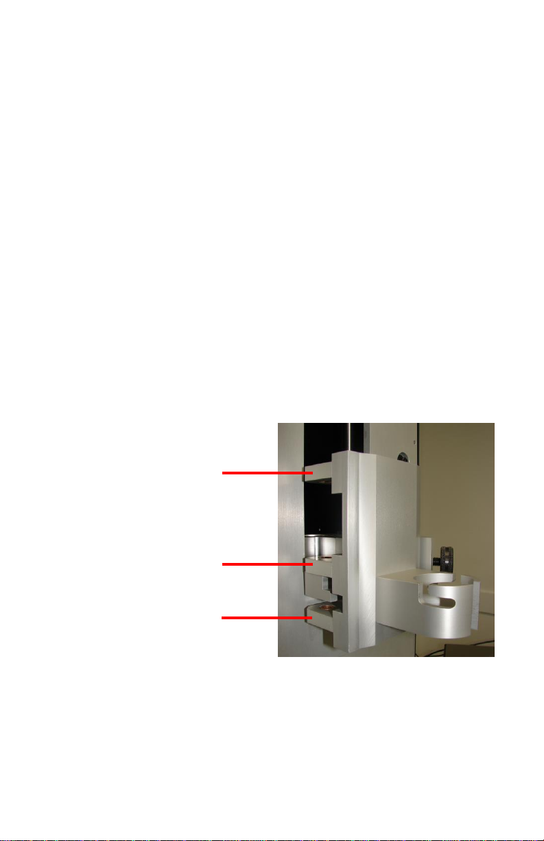
13. CARTRIDGE HOLDER INSTALLATION
Refer to Fig. 15.0 and 16.0
The TS6500CIM-6 is setup to mix the 6.0oz. (160ml) kit. To mix the 2.5oz (60ml)
or 8.0oz. (220ml) kit the cartridge holder needs to be re-installed at the correct
mounting locations as shown in Fig. 15.
Figure 15.0 Mounting Location
MOUNTING LOCATION
2.5oz (60ml) KIT
MOUNTING LOCATION
6.0oz (160ml) KIT
MOUNTING LOCATION
8.0oz (220ml) KIT
20
The cartridge holder can be installed in a few simple steps:
1. Pull the release knob and push the fluid level sensor assembly to the left.
2. Loosen the locking screw by turning it counter clockwise.
3. Rotate the cartridge holder outward and pull it up to remove from the
machine.
4. Install new cartridge holder in the reverse order.
5. Pull release knob to rotate fluid level sensor assembly back into position.
Figure 16.0 Cartridge Holder
RELEASE KNOB
FLUID LEVEL
SENSOR
CARTRIDGE HOLDER
LOCKING SCREW
Table of contents
Languages:
Other TECHCON SYSTEMS Medical Equipment manuals


Popular Medical Equipment manuals by other brands

Basic American
Basic American Slide-W-I-D-E ZZ98674 Supplemental service manual

Medelco
Medelco OmniPlinth user manual

SPIRIVA
SPIRIVA Respimat re-usable Instructions for use

Instramed
Instramed EazyPro quick start guide

Enraf Nonius
Enraf Nonius TENSMED S82 Instructions for use

ConvaTec USA
ConvaTec USA Natura Ostomy System How to use

Blackrock Microsystems
Blackrock Microsystems Cerebus NeuroPort Instructions for use

React Health
React Health BMC Luna II CPAP user manual

BROWNMED
BROWNMED Intellinetix Vibrating Knee/Elbow Wrap manual

Invacare
Invacare Platinum IRC5LXAW user manual

Sirona
Sirona CEREC AC BLUECAM operating instructions

Satelec
Satelec ACteon i-Surge+ user manual


