Blackrock Microsystems Cerebus NeuroPort User manual
Manufacturer
630 Komas Drive | Suite 200
Salt Lake City | UT 84108 | USA
P +1 (801) 582-5533 | F +1 (801) 582-1509
www.blackrockmicro.com
Revision 16.00 / LB-0028 – Cerebus IFU – 2021/06
© 2021 Blackrock Microsystems, LLC
Cerebus
Instructions for Use

Revision 16.00 / LB-0028 – Cerebus IFU
© 2021 Blackrock Microsystems, LLC
2
Table of Contents
What this Manual Covers ...................................................... 4
Packing Contents ............................................................................. 4
Host PC Requirements .................................................................... 4
Setup Overview ............................................................................... 5
Intended Use and Indications for Use ................................... 5
Contraindications, Warnings, and Precautions ..................... 6
Warnings .......................................................................................... 6
Precautions ...................................................................................... 6
Symbols ............................................................................... 7
Specifications ................................................................... 10
Neural Signal Processor ................................................................ 10
Digital Hub ..................................................................................... 11
Cerebus System Hardware ................................................. 12
Digital Hub 128 .............................................................................. 13
Status LEDs ................................................................................ 13
Power .......................................................................................... 14
Fast Settle ................................................................................... 14
Digital Inputs ............................................................................... 14
Patient Ground ............................................................................ 14
Fiber Optic Link ........................................................................... 14
CerePlexTM Digital Headstages ..................................................... 14
Neural Signal Processor (NSP) .......................................... 15
NSP Front Panel ............................................................................ 16
NSP Back Panel ............................................................................ 17
Quick Setup Guide .............................................................. 19
Setting up the Digital Cerebus System .......................................... 19
Setting up the Ethernet Link .......................................................... 19

Revision 16.00 / LB-0028 – Cerebus IFU
© 2021 Blackrock Microsystems, LLC
3
Troubleshooting ............................................................................. 21
The NSP is stuck in the initializing step. ..................................... 21
How can I update the Cerebus firmware on the NSP to the latest
version? ....................................................................................... 21
To install Central Windows Suite: ............................................... 21
The fiber optic LED indicator is illuminating yellow or red. .......... 22
The source status LED on Digital Hub is illuminating yellow or red.
.................................................................................................... 23
The Central application fails to start. ........................................... 23
Return Merchandise Authorization ...................................... 24
Warranty ............................................................................. 25
Support ............................................................................... 25
Complaints ..................................................................................... 25

Revision 16.00 / LB-0028 – Cerebus IFU
© 2021 Blackrock Microsystems, LLC
4
What this Manual Covers
The Blackrock Cerebus Neural Processing System supports recording, processing and
displaying bio-potential signals from various types of electrodes. Bio-potential signals
may include Electrocorticography (ECoG), electroencephalography (EEG),
electromyography (EMG), electrocardiography (ECG), electrooculography (EOC), action
potentials (AP), and evoked potentials (EP).
The Cerebus System records and processes neural signals from up to 256 surface or
penetrating electrodes in addition to auxiliary analog signals and digital experimental
events. Multiple systems can be synchronized to achieve higher input channel counts.
The system can perform real-time signal processing algorithms including noise
cancellation, digital filtering, simultaneous extraction of spike and field potentials, manual
and automatic online spike sorting. Functionality can be further increased with custom
user-defined scripts.
The Cerebus System includes a Digital Hub. The Digital Hub allows the Cerebus System
to be used with CerePlex™ digital headstages which digitize and multiplex neural
signals to reduce lead wire size and noise acquisition.
Packing Contents
The Cerebus System is shipped with components listed below. The exact type
and quantity of the components can vary depending on the Cerebus model, line
voltage (110v or 220v), and total input channel count.
• Neural Signal Processor (NSP) and rubber feet
• Rack mounting ears and screws
• Digital Hub 128 and isolated power supply
• Alligator clip to touch proof ground cable
• Power cables and connectors
• Crossover Ethernet cable
• Cerebus user’s manual & Central Suite software installation CD
Host PC Requirements
The recommended specifications for a Cerebus System host PC are mentioned
below.
• Microsoft Windows 10 professional
• Intel Core i-series processor
• 8 GB RAM
• 250 GB SSD for operating system
• Separate SSD for data storage
• Discrete video/graphics card
• 2 gigabit Ethernet Ports
A Host PC that is configured and tested by our engineers is available. Please
contact [email protected] for more information.

Revision 16.00 / LB-0028 – Cerebus IFU
© 2021 Blackrock Microsystems, LLC
5
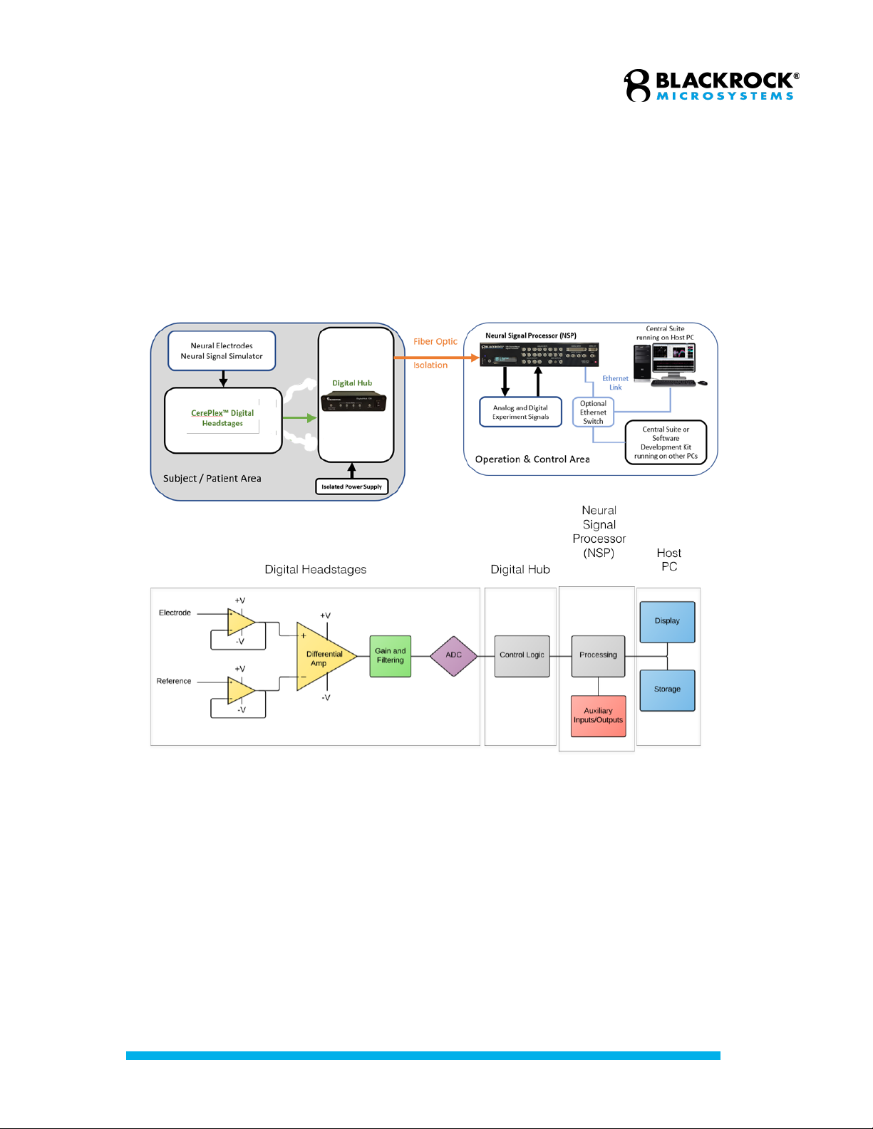
Setup Overview
The following diagrams depict overall views of how the Cerebus is integrated
within a typical laboratory environment. The experiment subject area is both
electrically and optically isolated from the experiment operation and control area.
The neural signals are digitized by the CerePlex digital headstages before they
enter the Digital Hub. The Digital Hub is responsible for converting the digitized
signals into fiber optic data and transferring them to the processor via a fiber
optic link.
The figure below (lower panel) also depicts a simplified flowchart to describe the
signal processing stages that take place inside the Cerebus system. The signals
on both the electrode and reference wire are initially buffered using unity gain
amplifiers. The buffered signals then enter a differential amplifier which subtracts
the neural signal from the reference to suppress common noise and achieve a
bipolar recording. The resultant signal then goes through the gain and filtering
stage. The amplified signal is then digitized, converted to fiber optic signal, and
transferred to the processor for further analysis, display or storage.
Intended Use and Indications for Use
The Blackrock Cerebus Neural Processing System supports recording, processing and
displaying bio-potential signals from various types of electrodes. Bio-potential signals
may include Electrocorticography (ECoG), electroencephalography (EEG),
electromyography (EMG), electrocardiography (ECG), electrooculography (EOC), action
potentials (AP), and evoked potentials (EP).

Revision 16.00 / LB-0028 – Cerebus IFU
© 2021 Blackrock Microsystems, LLC
6
Contraindications, Warnings, and
Precautions
Warnings
• Read this entire manual prior to using the device.
• A thorough understanding of the technical principles and risks associated
with electrophysiological recording is necessary before using this product.
• Always operate the Cerebus System in a clean environment.
• Only connect Cerebus System components to properly tested, grounded
and dedicated AC outlets using only the Blackrock provided power cable
to reduce the risk of electrical shock or malfunction of product. Do not use
an adapter for ungrounded wall outlets.
• Do not connect the Cerebus System to an outlet controlled by a wall
switch, multiple socket-outlet or extension cord to avoid fires or other
electrical hazards.
• Do not use the Cerebus System in the presence of flammable anesthetic
agents.
• Do not use the Cerebus System for any use other than its listed intended
use.
• Avoid strong static discharges from sources like televisions or computer
monitors because it can damage the electrical components of the system.
• Keep the Cerebus System away from liquids. Contact with water, shower
spray, or wet surfaces can lead to the patient receiving an electrical
shock.
• Connection of external instruments may compromise electrical safety
compliance with IEC 60601-1.
• The Cerebus System should be disconnected from any electrodes during
cardiac defibrillation.
• The conductive parts of electrodes and their connectors, including neural
electrodes, should not contact other conductive parts including earth.
• Place the Cerebus system in a secure location.
• Avoid tripping on cords connected to the Cerebus system.
• Repair or maintenance is not allowed during equipment operation.
• Only plug in Blackrock approved equipment into the Cerebus system.
• Do not connect the computer hosting the Central software to the internet.
• Do not turn on the digital hub until connections have been made between
the patient and the hub.
Precautions
• Follow the restrictions of use for third party electrodes or arrays.
• Third party recording or control systems connecting to the Cerebus
System and components must be electrically isolated for subject safety.
• Note that the fiber-optic cable is very delicate. Do not bend it (bend radius
of 5.0 cm) or crush it.
Revision 16.00 / LB-0028 – Cerebus IFU
© 2021 Blackrock Microsystems, LLC
7
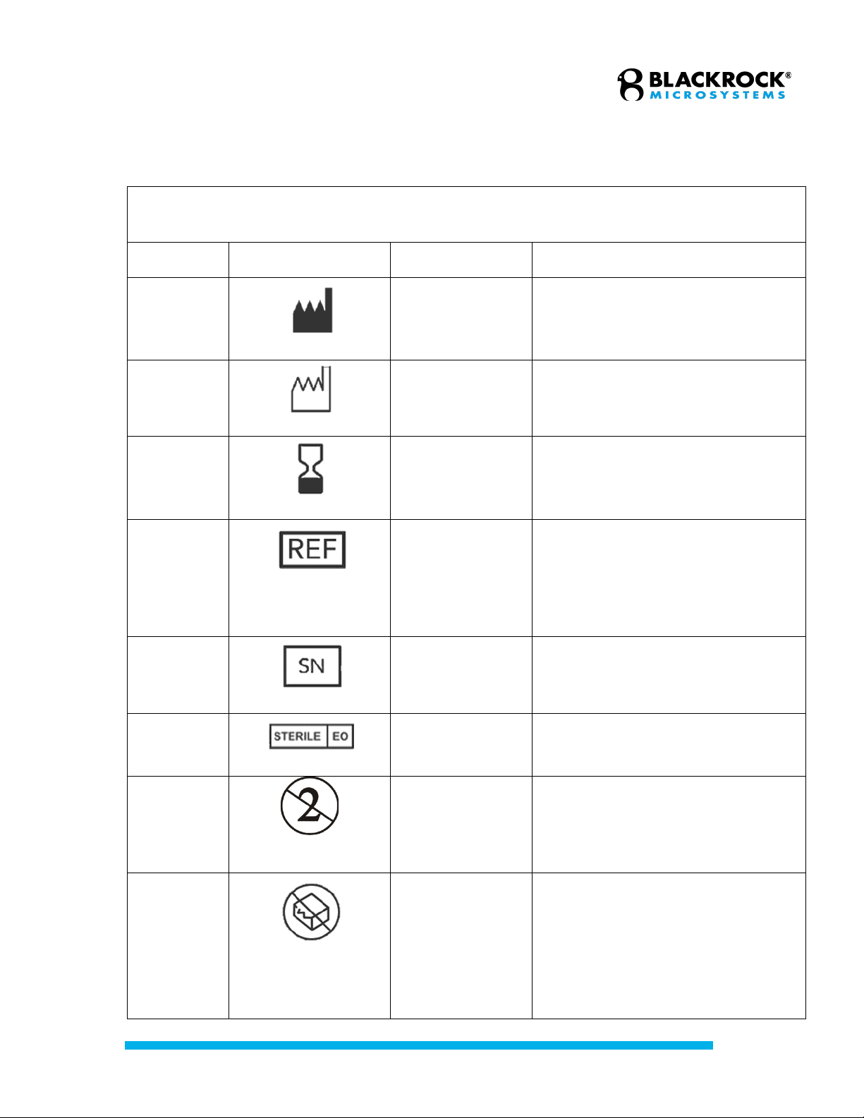
Symbols
ISO 15223-1:2016 Medical Devices – Symbols to Be Used with Medical Device Labels,
Labeling, and Information to Be Supplied
Reference
Symbol
Title
Meaning
5.1.1
Manufacturer
Indicates the medical device
manufacturer.
5.1.3
Date of
Manufacture
Indicates date of manufacture and is
accompanied by a date.
5.1.4
Use-by Date
Indicates the date after which the
medical device is not to be used.
5.1.6
Catalog Number
Indicates the manufacturer’s catalog
number so that the device may be
identified. For Blackrock
Microsystems it is called the Part
Number (PN).
5.1.7
Serial Number
Indicates the manufacturer’s serial
number so that a specific medical
device can be identified.
5.2.3
Sterilized Using
Ethylene Oxide
Indicates that the device has been
sterilized using ethylene oxide.
5.2.6
Do Not Reuse
Indicates a medical device that is
intended for one use, or for use on a
single patient during a single
procedure.
5.2.8
Do Not Use if
Package is
Damaged
Indicates that a medical device
should not be used if the package
has been damaged or opened.
Revision 16.00 / LB-0028 – Cerebus IFU
© 2021 Blackrock Microsystems, LLC
8
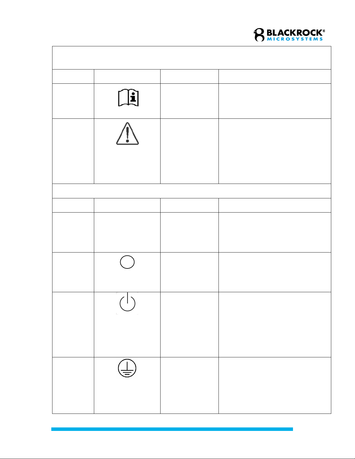
ISO 15223-1:2016 Medical Devices – Symbols to Be Used with Medical Device Labels,
Labeling, and Information to Be Supplied
Reference
Symbol
Title
Meaning
5.4.3
Consult
Instructions for
Use
Indicates the need for the user to
consult the instructions for use, which
you are currently reading.
5.4.4
Caution
Indicates the need for the user to
consult the instructions for use for
important cautionary information such
as warning and precautions that
cannot, for a variety of reasons, be
presented on the medical device
itself.
IEC 60417:2002 DB Graphical Symbols for Use on Equipment
Reference
Symbol
Title
Meaning
5007
|
On (Power)
To indicate connection to the mains,
at least for mains switches or their
positions, and all those cases where
safety is involved.
5008
Off (Power)
To indicate disconnection from the
mains, at least for mains switches or
their positions, and all those cases
where safety is involved.
5009
Standby (Power)
To identify the switch or switch
position by means of which part of
the equipment is switched on in order
to bring it into the stand-by condition,
and to identify the control to shift to or
to indicate the state of low power
consumption.
5019
Protective Earth
Ground
To identify any terminal which is
intended for connection to an
external conductor for protection
against electric shock in case of a
fault, or the terminal of a protective
earth (ground) electrode.

Revision 16.00 / LB-0028 – Cerebus IFU
© 2021 Blackrock Microsystems, LLC
9
IEC 60417:2002 DB Graphical Symbols for Use on Equipment
Reference
Symbol
Title
Meaning
5021
Equipotentiality
Connector
To identify the terminals which, when
connected together, bring the various
parts of an equipment or of a system
to the same potential, not necessarily
being the earth (ground) potential,
e.g. for local bonding.
5036
Dangerous
Voltage
To indicate hazards arising from
dangerous voltages.
5333
Type BF Applied
Part
To identify a type BF applied part
complying with IEC 60601-1.
IEC 60101-1:2012 Medical Electrical Equipment: Basic Safety and Essential Performance
Reference
Symbol
Title
Meaning
0102
Danger of
Electrostatic
Discharge
Danger of Electrostatic Discharge

Revision 16.00 / LB-0028 – Cerebus IFU
© 2021 Blackrock Microsystems, LLC
10
Specifications
Neural Signal Processor
Model Name
NeuroPort Neural Signal Processor
Neural Signal Inputs
Up to 256
Sampling Rate
30,000 Hz
Analog Inputs
Sixteen ±5 V, 16-bit inputs for experiment or neural signal processing
Digital IO
One 16-bit input port (DB-37) with Word and Packet Strobe control lines.
One RS232 I/O port (DB-9) with
115k baud input and output.
Four single-bit digital outputs (BNC) with programmable monitoring functions.
One TTL output (BNC) sampling synchronization output port.
Analog Outputs
Four ±5 V, 600 ohm, 16-bit outputs
Audio Outputs
Two ±1.5 V line-level outputs
PC Interface
1 Gbps Ethernet
Power Requirements
110 VAC 60 Hz 6.0 A / 240 VAC 50 Hz 3.0 A
Line Noise Serviceable Fuses
5 x 20mm, 250V, 1.6A, Slow Blow
Compliance Standards
IEC 60601-1, IEC 60601-1-2, IEC 60601-2-26, CSA listed
Type of Protection Against Electric
Shock
Class I
Degree of Protection
Type BF Applied Part
Mode of Operation
Continuous
Ingress Protection
Ordinary Equipment, not fluid resistant, IPX0
Operating Environment
10˚C to 35˚C, 5 to 85% R.H. (non-condensing)
Storage Environment
-20˚C to 50˚C, 5 to 95% R.H. (non-condensing)

Revision 16.00 / LB-0028 – Cerebus IFU
© 2021 Blackrock Microsystems, LLC
11
Digital Hub
Model Name
Digital Hub
Power Requirements
100-240V 50/60 Hz, 1.5 A
Sampling Frequency
48 MHz or 66 MHz
Mode of Operation
Continuous
Input Protocol
Low-voltage differential signaling
Ingress Protection
Ordinary Equipment, not fluid resistant, IP20
Operating Environment
10˚C to 40˚C, 5 to 95% R.H. (non-condensing)
Storage Environment
-20˚C to 50˚C, 5 to 100% R.H. (non-condensing)
Revision 16.00 / LB-0028 – Cerebus IFU
© 2021 Blackrock Microsystems, LLC
12
Cerebus System Hardware
The Digital Cerebus System is compatible with the whole family of the Blackrock
CerePlex digital headstages. Blackrock digital headstages enable low noise
transmission in a minimally invasive package. The output of the CerePlex digital
headstages are multiplexed, meaning that only a reduced set of wires are needed to
transmit the already digitized data from all the input channels. The following block
diagram depicts the different components and their roles within a Digital Cerebus
System.
Simplified block diagram showing different components of the Digital Cerebus and their
intended function within the system.
Revision 16.00 / LB-0028 – Cerebus IFU
© 2021 Blackrock Microsystems, LLC
13
Digital Hub 128
The Blackrock Digital Hub provides an interface between the NSP and CerePlex
digital headstages. The Digital Hub converts digital signal to an optic-digital
format which is sent directly to the NSP. This dramatically reduces the noise
introduced to the signal during transmission. The Digital Hub can handle many
possible configurations when it is connected to multiple CerePlex digital
headstages provided that the total number of channels does not exceed
maximum 128 channels.
The Blackrock Digital Hub has several possible configurations which arise from
its ability to transmit 128 channels of data. For instance, the Digital Hub can be
used with:
• Four 32-channel CerePlex M headstages
• Two 64-channel CerePlex M headstages
• One 32-channel and one 96-channel CerePlex M headstage
• One CerePlex E
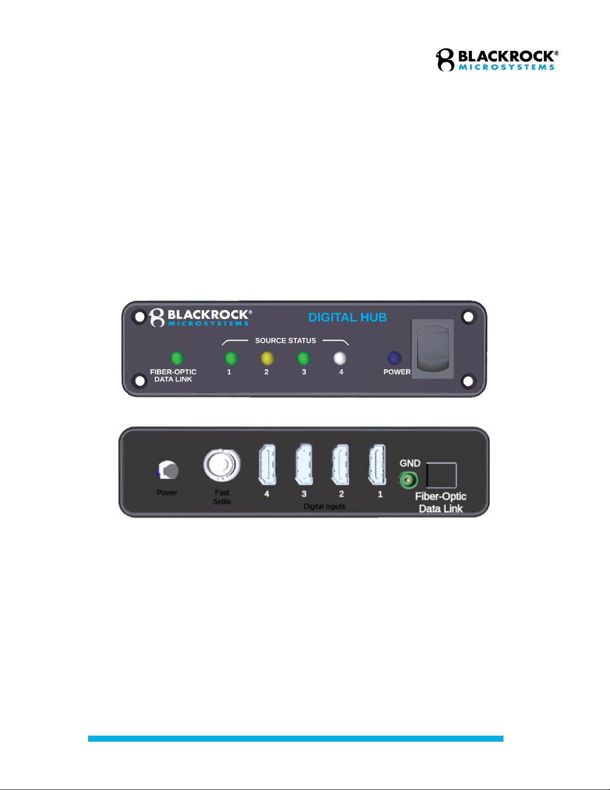
Status LEDs
There are six LED’s on the Digital Hub which can give the user
information about the device status. If the Digital Hub is powered
(plugged in) the “Power” LED will be blue as in Fig 3-1. If the fiber-optic
connection between the NSP and the Digital Hub is present, the “Fiber
Optic Data Link” LED will be green (otherwise yellow). Finally, LED’s 1-4
show the source status of the incoming data streams. If the LED is green
for an input (such as inputs 1 & 3 in Fig 3-1) the Digital Hub is receiving
data from a CerePlex correctly. If the LED is yellow (such as show in
input 2 in Fig 3-2) data is not being transmitted to the Digital Hub
correctly. If the input LED is not lit (such as shown in input 4 Fig 3-1)
there is either no data being received or the HDMI cable is not plugged
into the input slot.
Status LEDs
Front (top) and Back (bottom) of the Digital Hub

Revision 16.00 / LB-0028 – Cerebus IFU
© 2021 Blackrock Microsystems, LLC
14
Power
The Digital Hub is powered by a medical grade power supply that is
included as part of the Digital Hub packaging. The blue LED labeled
“Power” will light up when the external power supply is connected to the
unit and turned on. Note that the hub should not be turned on until after
connections to the headstage and subject are made.
Fast Settle
The fast settle input connector is located on the back panel of the Digital
Hub. This connector is tied to each of the four HDMI inputs. The signal
fed into the BNC connector is passed through the system to pin 14 on the
HDMI connector, providing a fast settle signal to the attached digital
headstage(s).
Digital Inputs
The Digital Hub is designed so that input one has the highest priority,
then input two, and so forth. This means that if two 96 channel CerePlex
M’s are connected, in inputs two and three respectively, input two will
send the entire 96 channels to the Neural Signal Processor (NSP) but
input three will send only the first 32 channels to the NSP. The Digital
Hub will always send the first 128 channels to the NSP in this way, unless
there are less than 128 channels in which case it will send all channels.
The HDMI connector pin-out is shown in Figure 3-2 below.
Patient Ground
This connector is located on the back panel of the Digital Hub and is
labeled as “GND.” This is the patient ground connector if needed for a
reference ground.
Fiber Optic Link
This connector is located on the back panel of the Digital Hub and
provides a connection to the Blackrock Neural Signal Processor via a
fiber optic cable.
CerePlexTM Digital Headstages
Blackrock Microsystems manufactures a range of different models of CerePlex
digital headstages which are characterized by their low noise, light weight and
small physical profile. These headstages are all compatible with the Digital Hub
128. For more detailed information on each type of the headstage please refer to
www.blackrockmicro.com.
Revision 16.00 / LB-0028 – Cerebus IFU
© 2021 Blackrock Microsystems, LLC
15
Neural Signal Processor (NSP)
The NSP is a real-time processor of the Cerebus System which performs all the digital
processing, including filtering, spike extraction, spike sorting, and so on. The NSP is
built upon a real-time Linux system capable of onboard closed loop processing and rapid
data transmission to the Host PC through Ethernet UDP protocol. The NSP has multiple
auxiliary analog and digital inputs and outputs that can be programmed through the
Cerebus Central Software Suite or one of the supplied Software Development Kits
(SDKs). The NSP can also perform real-time closed loop analysis via the Extension
Code user-developed applications and communicate the results via the auxiliary ports to
third-party equipment or via the Ethernet link to the host PC. Multiple NSPs may also be
synchronized for recording signals from more electrodes.
The hardware and architecture inside the NSP are both periodically optimized to improve
the overall performance and reliability of the system. Blackrock Microsystems has so far
released four different versions of the NSP mentioned below:
• NSP 1.0 (Part number 4176)
• NSP 1.5 (Part number 7530)
• NSP 1.75 (Part number 9650)
• NSP 2.0 (Part number 10411)
NSP 1.0 architecture was based on an Intel® Pentium 4 processor. The processor in the
NSP 1.5 was upgraded to multi-core Intel® i7 technology. The mentioned upgrade
provides users with the NSP versions 1.5 and above an option to directly upload their
custom-built software into the NSP for real-time execution via the Blackrock’s Extension
Software package. For detailed information about Extension software and example
application notes, please refer to www.blackrockmicro.com .
NSP 2.0 is equipped with an additional fiber optic input link therefore it can receive and
process 256 channels of neural data simultaneously. All previous versions of the NSP
can handle maximum 128 channels via a single fiber optic link.
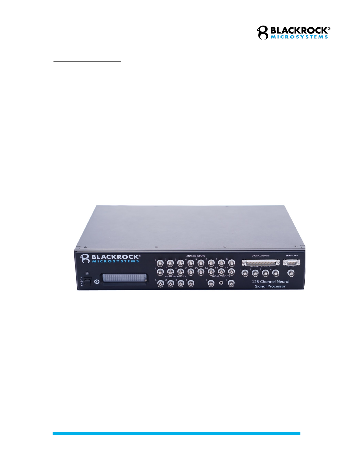
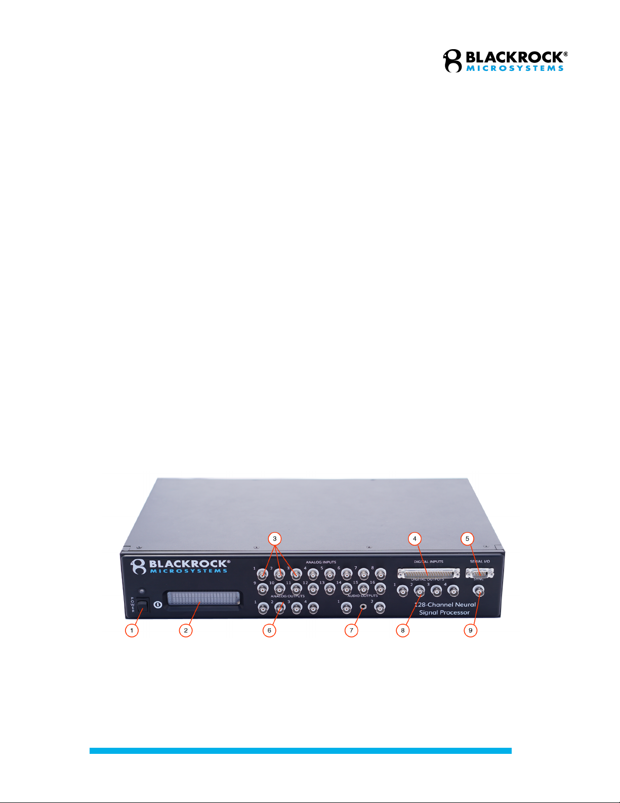
Front side of the NSP 1.75 showing the power switch (1), LCD display (2), analog inputs (3), digital
inputs (4), serial I/O (5), analog outputs (6), audio outputs (7), digital outputs (8), and sync port (9).
Note: The fiber optic link input connector has been relocated to the back panel in NSP versions
1.75 and above. The location of this port was previously under the sync port on the front panel.
Revision 16.00 / LB-0028 – Cerebus IFU
© 2021 Blackrock Microsystems, LLC
16
The available input and output connection ports on the NSP are detailed in the following
sections.
NSP Front Panel
The front panel of the NSP (see picture above) consists of the following input and
output ports:
1. Power switch:
The power switch turns the NSP on and off. The LED above the switch
will illuminate when the unit is on.
2. LCD Display:
The LCD displays the current operating status of the unit. The statuses
include “Initializing”, “NSP Startup”, “NSP Running”, “NSP Standby”, and
“Synchronized”.
3. Analog Inputs:
Auxiliary analog signals can be recorded through 16 BNC ports. The
analog source may range ±5.0 V and should come from a source
impedance of less than 100 Ω. The coupling of each input channel can
be manually selected in the software. By default, channels 1-8 are AC-
coupled and channels 9-16 are DC-coupled.
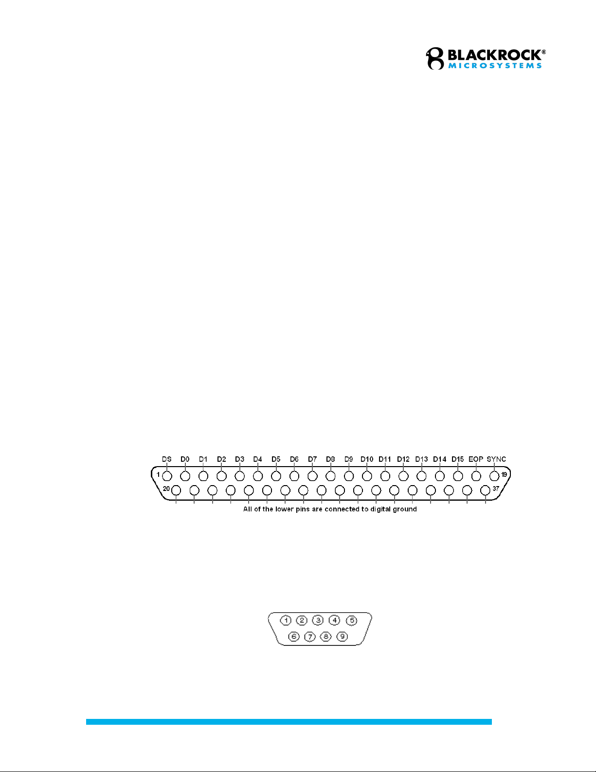
4. Digital Input:
Digital events can be recorded through the 16-bit DB37 input port. The
pinout is shown below. DS is a digital strobe pin. D0-15 are data pins.
EOP is reserved. SYNC is an output pin and can be used with external
equipment to indicate when the port is scanned. Input range is 0V-5V TTL
levels. The port is polled every 1/30000 of a second. Strobed data is
buffered up to 10 strobes per 1/30000 of a second and is latched on the
rising edge of the DS pin.
5. Serial I/O:
The port is an RS232 DB9 digital input/output port. The pin diagram is
shown below. Currently, the NSP firmware software only supports this
port as an input.
Pin 2 is “Receive Data”, pin 3 is “Transmit Data”, and pin 5 is “Ground”.
The configuration of the port is: Baud rate: 115200, Data bits: 8, Parity:
none, Stop bits: 1, Flow control: disabled.
Digital input pin diagram.
Serial I/O pin diagram.

Revision 16.00 / LB-0028 – Cerebus IFU
© 2021 Blackrock Microsystems, LLC
17
6. Analog Outputs:
Four ±5.0 V analog output BNC connectors can be used to send
monitoring signals or stimulus waveforms to other connectors.
7. Audio Output:
The system sends a ±1.5 V line-level audio signal of the selected data
channel to two BNC ports and one 3.5mm female stereo audio connector
simultaneously.
8. Digital Outputs:
Four single-bit digital BNC outputs can be programmed for monitoring or
timing functions. These ports can be setup to send a TTL signal if spike
activity is detected on any channel. They can also be configured to output
a digital pulse train at a user-defined frequency and duty cycle. Digital
Output 1 can also be used for syncing external equipment by sending a
unique pulse every 14 seconds. The entire sync pattern will repeat every
hour. See the Central Software Suite User Manual for more details.
9. Sync Port:
A synchronization pulse can be set as an optional line to inform external
equipment when the NSP neural signal inputs and front panel ports are
scanned. It is active on the rising edge of the signal.
NSP Back Panel
The back panel of the NSP includes the following ports and connectors:
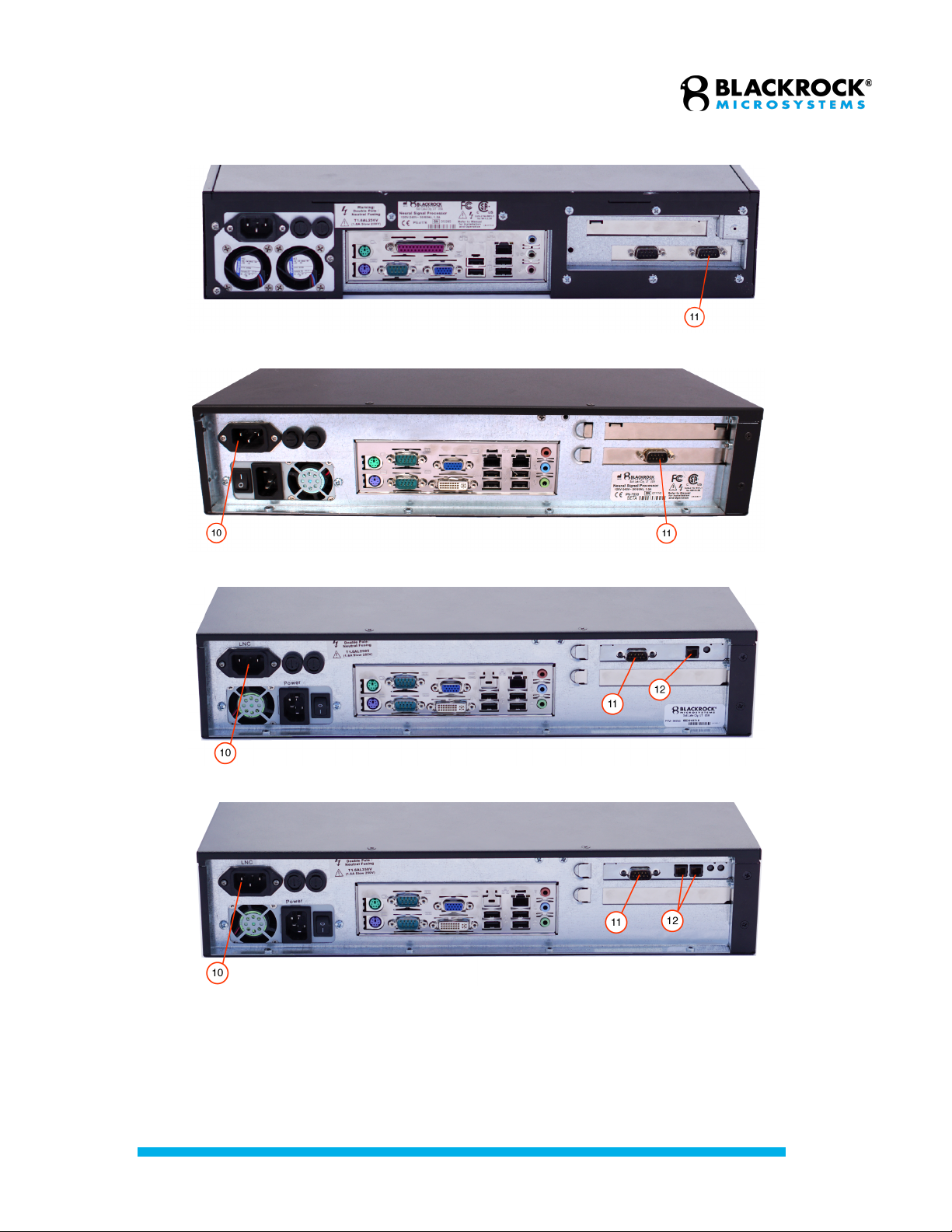
1. Line Noise Cancellation Port:
On NSP 1.5 and higher versions, the adaptive line noise cancellation port
is separated from the NSP’s main power input connector. To use the
adaptive line noise cancellation, plug a standard power cable into this port
and enable the feature in software as described in the Central Software
Suite User Manual which is available for download from the Blackrock
Microsystems website.
2. Synchronization Port:
This DB9 port is located on the back of the NSP and it is used to
synchronize two or more NSPs. Once the sync cable (Blackrock PN
5584) is properly connected between NSPs, they will automatically
synchronize. Some older NSP models may not have this port. To add
synchronization capability to your NSP, please contact Blackrock
Microsystems at sales@blackrockmicro.com.
3. Fiber Optic Link:
This port connects to the Digital Hub using a fiber optic cable. A LED to
the right of the connector turns green when an optical link is established
and, in the newest model of the Neural Signal Processor (NSP 2.0 and
above) turns yellow when the link is broken. Older models of the device
have a red LED when the link is broken. The Fiber Optic connector is
located on the front side in NSP models 1.5 and 1.0. The NSP 2.0 is
equipped with an additional fiber optic input connector which enables the
NSP 2.0 to communicate with more than one Digital Hub.
Revision 16.00 / LB-0028 – Cerebus IFU
© 2021 Blackrock Microsystems, LLC
18
NSP 1.0
NSP 1.5
NSP 1.75
NSP 2.0
Back panel view of different versions of NSP showing the adaptive Line Noise Cancellation plug
(10), Synchronization Port (11), and the Fiber Optic input connector(s) (12).

Revision 16.00 / LB-0028 – Cerebus IFU
© 2021 Blackrock Microsystems, LLC
19
Quick Setup Guide
Setting up the Digital Cerebus System
1. Remove the NSP, Digital Hub and Digital Hub’s power supply from the
shipping boxes.
2. Attach the NSP rack-mount brackets to install it in an equipment rack, or
rubber feet to place it on a table.
3. Plug in the NSP and the Hub power supply to electrical outlets.
4. Connect the power supply to the Digital Hub.
5. Connect one end of the fiber-optic cable to the NSP and the other end to
the Digital Hub.
6. Turn on the NSP, then the Digital Hub.
7. If available, connect a CerePlex headstage to the Digital Hub via an
appropriate HDMI cable.
8. The LEDs on the Hub and the NSP should turn green if everything is
connected properly.
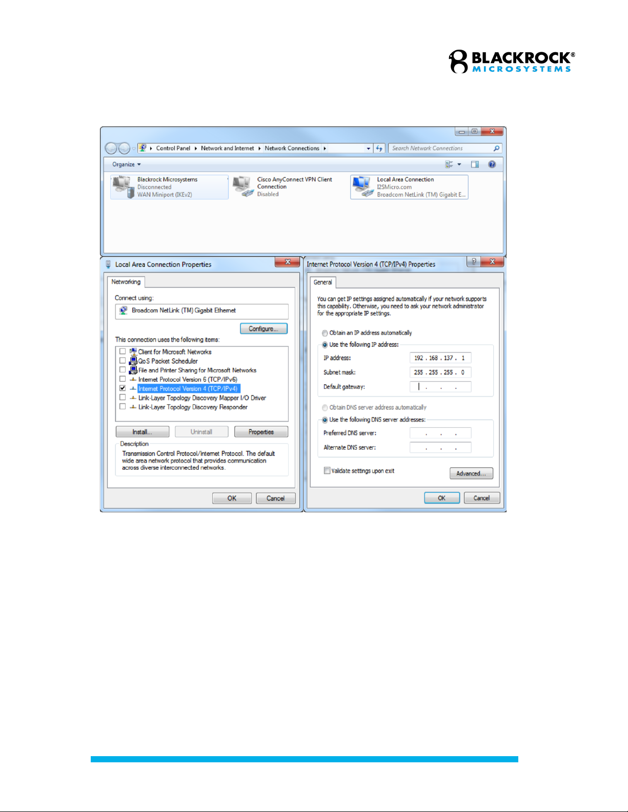
Setting up the Ethernet Link
The network interface card on the Host PC needs to be configured as follows for
connecting the Host PC to the NSP:
1. In Windows click on Start and search for “View Network Connections”.
2. Right click on the correct Ethernet Adaptor (usually, Local Area
Connection) and click on Properties.
3. Uncheck all services except for Internet Protocol (TCP/IP) or Internet
Protocol Version 4 (TCP/IPv4).
4. Click on Internet Protocol (TCP/IP) and click on Properties
5. For IP Address enter 192.168.137.1, for Subnet Mask enter
255.255.255.0 and leave the rest blank.
6. Click on OK to save changes.
Up to 16 PCs can be connected to the same NSP using a business class 1-Gbps
network switch. For other PCs connected using a network switch, IP addresses
should increment, such as 192.168.137.2, 192.168.137.3, etc. The NSP’s IP
address is currently fixed at 192.168.137.128.
Revision 16.00 / LB-0028 – Cerebus IFU
© 2021 Blackrock Microsystems, LLC
20
Setting the network properties on the Host PC.
Table of contents
Other Blackrock Microsystems Medical Equipment manuals


