manuals.online logo
Brands
  1. Home
  2. •
  3. Brands
  4. •
  5. Technics
  6. •
  7. Cassette Player
  8. •
  9. Technics RS-B965 User manual

Technics RS-B965 User manual

Other manuals for RS-B965

1

Other Technics Cassette Player manuals

Technics RS-BR465 User manual

Technics

Technics RS-BR465 User manual

Technics RS-TR575 User manual

Technics

Technics RS-TR575 User manual

Technics RS-BX747 User manual

Technics

Technics RS-BX747 User manual

Technics RS-B755 User manual

Technics

Technics RS-B755 User manual

Technics RS-676US User manual

Technics

Technics RS-676US User manual

Technics RS-TR474 User manual

Technics

Technics RS-TR474 User manual

Technics RS-BX828 User manual

Technics

Technics RS-BX828 User manual

Technics RS-M250 User manual

Technics

Technics RS-M250 User manual

Technics RS-TR575 User manual

Technics

Technics RS-TR575 User manual

Technics RS-TR474 User manual

Technics

Technics RS-TR474 User manual

Technics RS-M205 - SERVICE User manual

Technics

Technics RS-M205 - SERVICE User manual

Technics RSTR272 - DUAL CASS. RECORDER User manual

Technics

Technics RSTR272 - DUAL CASS. RECORDER User manual

Technics RS-B465 User manual

Technics

Technics RS-B465 User manual

Technics RS-M228X User manual

Technics

Technics RS-M228X User manual

Technics RS-BX606 User manual

Technics

Technics RS-BX606 User manual

Technics RS-M7 User manual

Technics

Technics RS-M7 User manual

Technics RS-AZ6 User manual

Technics

Technics RS-AZ6 User manual

Technics RS-TR575 User manual

Technics

Technics RS-TR575 User manual

Technics RS-AZ7 User manual

Technics

Technics RS-AZ7 User manual

Technics RS-TR165 User manual

Technics

Technics RS-TR165 User manual

Technics RS-B605 User manual

Technics

Technics RS-B605 User manual

Technics RS-M04 User manual

Technics

Technics RS-M04 User manual

Technics RS-M235X User manual

Technics

Technics RS-M235X User manual

Technics RS-D200 User manual

Technics

Technics RS-D200 User manual

Popular Cassette Player manuals by other brands

Ahuja CPA-360 Operation manual

Ahuja

Ahuja CPA-360 Operation manual

Sony Pressman TCS-60DV Specifications

Sony

Sony Pressman TCS-60DV Specifications

Philips AQ6485/14 Product information

Philips

Philips AQ6485/14 Product information

Sony TCM-200DV - Cassette Recorder operating instructions

Sony

Sony TCM-200DV - Cassette Recorder operating instructions

Nakamichi BX-300 Service manual

Nakamichi

Nakamichi BX-300 Service manual

Panasonic RQ-E25V operating instructions

Panasonic

Panasonic RQ-E25V operating instructions

Aiwa TP-VS535 operating instructions

Aiwa

Aiwa TP-VS535 operating instructions

Yamaha MT8X Operation manual

Yamaha

Yamaha MT8X Operation manual

Sherwood Newcastle D-480 operating instructions

Sherwood

Sherwood Newcastle D-480 operating instructions

Manta MA408 user manual

Manta

Manta MA408 user manual

GPO W0162B user guide

GPO

GPO W0162B user guide

Marantz CP230 Service manual

Marantz

Marantz CP230 Service manual

Sony HST-471 Service manual

Sony

Sony HST-471 Service manual

Sharp JC-AV1 Operation manual

Sharp

Sharp JC-AV1 Operation manual

Pioneer CT-W103 Service manual

Pioneer

Pioneer CT-W103 Service manual

Sony CFS-B15 - Am/fm Stereo Cassette Recorder operating instructions

Sony

Sony CFS-B15 - Am/fm Stereo Cassette Recorder operating instructions

Sony WMFS220 - Portable Sports AM/FM Cassette... operating instructions

Sony

Sony WMFS220 - Portable Sports AM/FM Cassette... operating instructions

Aiwa HS-TA21 operating instructions

Aiwa

Aiwa HS-TA21 operating instructions

manuals.online logo
manuals.online logoBrands
  • About & Mission
  • Contact us
  • Privacy Policy
  • Terms and Conditions

Copyright 2025 Manuals.Online. All Rights Reserved.

ORDER
NO.
AD9002237C8
Service
Manual
Cassette
Deck
Dolby
NR-Equipped
Stereo
Cassette
Deck
DC
(Batey
5-c
wa
Hx
PRO]
*
HX
Pro
headroom
extension
originated
by
Bang
Olufsen
and
manufactured
under
license
from
Dolby
Laboratories
Licensing
Corporation.
“DOLBY”,
the
double-D
symbol,
and
‘HX
PRO”
are
trademarks
of
Dolby
Laboratories
Licensing
Corporation.
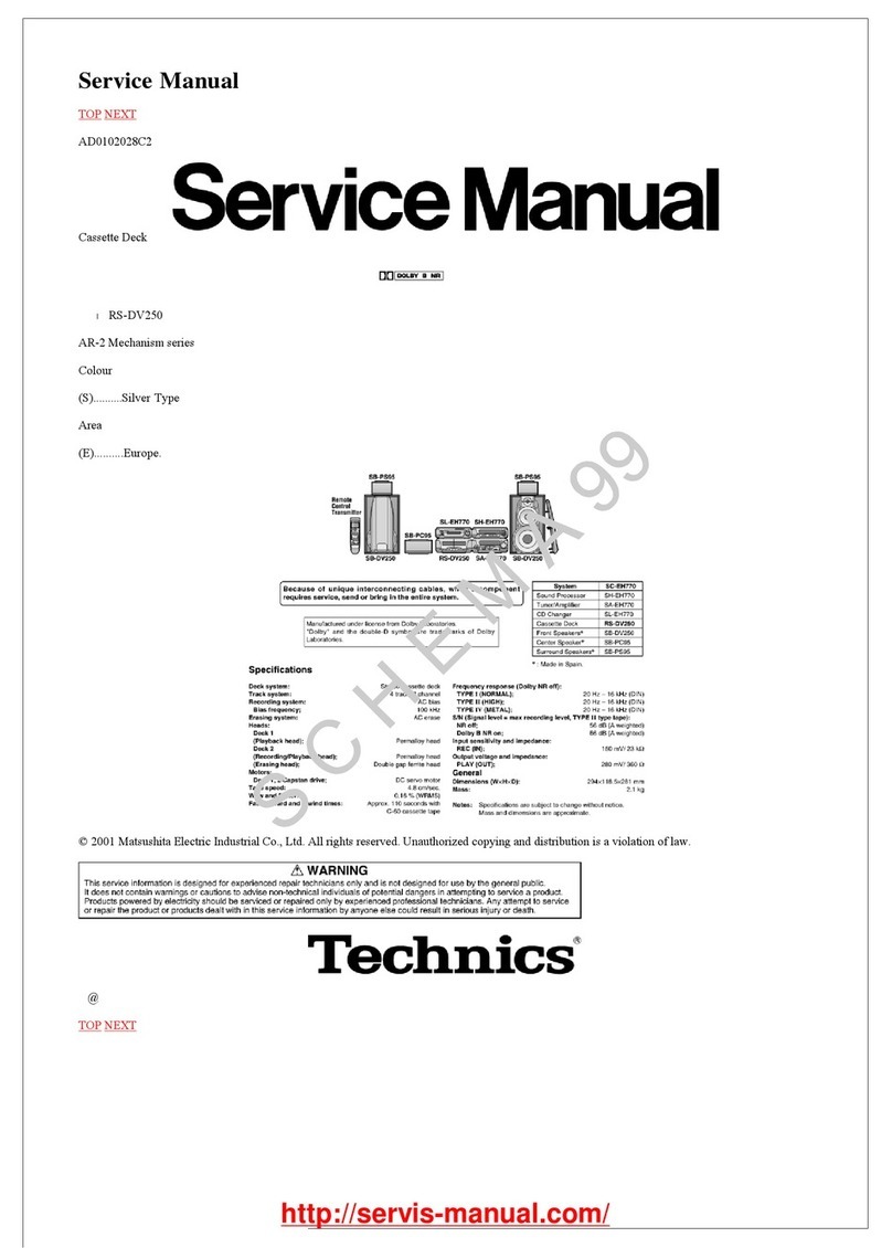
RS-B755
MECHANISM
SERIES
(AR350)
Mi
SPECIFICATIONS
m
CASSETTE
DECK
SECTION
Deck
system
Stereo
cassette
deck
Track
system
4-track,
2-channel
Heads
Record
Permalloy
(Combination)
Playback
Permalloy
(Combination)
Erasure
Double-gap
ferrite
Motors
Capstan
drive
Quartz
DD
motor
Reel
table
drive
DC
motor
Cassette
hoider
open/close
DC
motor
Recording
system
AC
bias
Bias
frequency
80
kHz
Erasing
system
AC
erase
Tape
speed
Frequency
response
4.8cm/sec.
NORMAL
20
Hz~19
kHz
20
Hz~18
kHz
(DIN)
Cro:
20
Hz~20
kHz
20
Hz~19
kHz
(DIN)
METAL
20
Hz~21
kHz
20
Hz~20
kHz
(DIN)
S/N
(signal
level=max
recording
level,
CrOz
type
tape)
Dolby
C
NR
on
74
dB
(CCIR)
Dolby
B
NR
on
66
dB
(CCIR)
Dolby
NR
oft
57
dB
(A
weighted)
Technics
RS-B965
Color
(K)...
Black
Type
Area
Continental
Europe.
(EG)
F.
|
F.R.
Germany
and
Italy.
|
|
F.R.
Germany
and
Italy.
|
and
Italy.
Asia,
Latin
America,
(GC)
Near
East,
and
Africa.
(K)
Wow
and
flutter
0.05%
(WRMS)
+0.14%
(DIN)
Fast
forward
and
rewind
times
Approx.
90
seconds
with
C-60
cassette
tape
input
sensitivity
and
impedance
LINE
“60
mV/47
kQ
Output
voltage
and
impedance
LINE
400
mV/800Q
HEADPHONES
125
mV/8Q
(8Q~6000)
@
GENERAL
Power
consumption
21W
Power
supply
For
Continentai
Europe,
F.R.
Germany
and
Italy
AC
50
Hz/60
Hz,
220
V
For
Great
Britain
and
Oceania
AC
50
Hz/60
Hz,
240
V
For
others
AC
50
Hz/60
Hz,
110
V/127-V/220
V/240
V
Dimensions
(W
x
H
x
D)
430
x
135
x
290
mm
Weight
6.4
kg
Note:
Specifications
are
subject
to
change
without
notice.
Weight
and
dimensions
are
approximate.
Matsushita
Electric
Industrial
Co.,
Ltd.
Central
P.O.
Box
288,
Osaka
530-91,
Japan
Mi
CONTENTS
Page
MAINTENANCE
(5
:5<soscsccsseocesbsndsocs
sacacoesesdecsaavecestatacesntstestevcees
2
ACCESSORIES
cis
nesccsacsasssctavscssascuscaseececueacscvscossescacacasseaneabectense
2
CONNECTIONS
ivsssssncisccessncsscssnnsseseoncossnasivasenccidashoceaiovesenesennzsass
3
FRONT
PANEL
CONTROLS
AND
FUNCTIONS...
ae
4,5
RECORDING
WITH
HIGH
TONE
QUALITY
..............:c000-
6~9
DISASSEMBLY
INSTRUCTIONG..............csccssccsssscesereees
10~15
MEASUREMENT
AND
ADJUSTMENT
METHODES....
16~21
TERMINAL
FUNCTION
OF
IC’S..........cccccscsssssscsssecceenenes
22,
23
BLOCK
DIAGRAM
Mi
MAINTENANCE
Head
care
a
To
assure
good
sound
quality
for
recording
and
playback,
be
sure
to
clean
the
heads
after
approximately
every
10
hours
of
use.
1)
Press
the
open/close
button.
2)
Press
the
power
“standby
(!)/on”
switch
to
turn
the
unit
off.
3)
Clean
the
heads,
pinch
roller
and
the
capstan
shaft
with
a
cotton
swab
(or
with
a
soft,
lint-free
cloth)
slightly
moistened
with
alcohol.
Do
not
use
any
solution
other
than
alcohol
for
head
cleaning.
Capst
Pee
Cotton
Swab
Pinch
Roller
Erase
Head
Pinch
Roller
Capstan
Record/Play
Head
Mi
ACCESSORIES
¢
Stereo
connection
cable
.........
0...
c
eee
cee
eee
(SUP2249-3)
@
AC
plug
adaptor...
6...
cece
nee
(SJP9215)
For
(GC)
area
only.
Page
TERMINAL
GUIDE
OF
IC’s,
TRANSISTORS
AND
DIODES........c.eseccssscssssssesssserseacorees
39
INTERNAL
CONNECTION
OF
FL......
w-
40
WIRING
CONNECTION
DIAGRAM
uu.
ccccescceseccsccscesceccoees
41
PRINTED
CIRCUIT
BOARDG............
..
42~46
REPLACEMENT
PARTS
LIST.............sccscssscssssessessserseses
47~50
EXPLODED
VIEWS.
.........ssccsscesssssssseeccsssetsssesecsssnranecessses
51~54
REPLACEMENT
PARTS
LIST...
wee
55,
56
PACKING
si
cen
cccenccciecetrecenencensennceucsiasesacsnndcssieas
nsatevceteaecveineadstdes
56
RESISTORS
&
CAPACITORG..............
--
57~60
XX
TECHNICAL
INFORMATION
XX
This
technical
information
is
located
on
pp
45-51
of
the
RS-B555
Service
Manual
(Order
No.
AD8907231C5).
Therefore,
refer
to
that
Service
Manual.
Head
demagnetization
In
order
to
maintain
good
sound
quality
during
recording
and
playback,
it
is
recommended
that
the
heads
should
be
demagne-
tized
if
distortion
or
poor
sound
quality
persist
after
cleaning
the
heads.
If
the
heads
become
magnetized,
they
could
create
noise
in
recordings,
loss
of
high-frequency
response,
or
erasure
of
valuable
recordings.
Several
types
of
head
demagnetizers
are
available
and
may
be
purchased
at
local
electronics
supply
stores.
Follow
the
instructions
that
are
supplied
with
the
device.
®Do
not
bring
any
type
of
metal
objects
or
tools
such
as
magnetic
screwdrivers
in
contact
with
the
head
assembly.
Maintenance
of
external
surfaces
To
clean
this
unit,
use
a
soft,
dry
cloth.
:
For
very
dirty
surfaces,
dip
a
soft
cloth
in
a
weak
soap-and-water
solution
and
wring
well.
After
cleaning,
wipe
with
a
Soft,
dry
cloth.
:
Never
use
alcohol,
paint
thinner,
benzine,
or
a
chemically
treated
cloth
to
clean
this
unit.
Such
chemicals
may
damage
the
unit's
finish.
*
AC
power
supply
Cord
.....
20...
1
RJA0004
(GC)
SFDACO5E03
(E,
EG)
SJA173-1
(GN)
SJA193-1
(EB)
Mi
CONNECTIONS
|
Follow
the
figures
below
to
connect
the
unit
with
other
units.
Make
sure
that
the
power
has
been
turned
off
to
the
units
while
they
are
being
connected.
Regular
connections
Amplifier
(XR)
(RX
(not
included)
=|
Stereo
connection
cables
(included)
AC
power
supply
cord
(included)
CD
player
(not
included)
=
s
Household
AC
outlet
This
unit
—
Direct
recording
from
CD
player
TAPE
REC
PLAY
OUT
BACK
QOQO0n
Cabalealtes)
cd
OOOOO
©OODODOOQDOOT
(LXR)
(RXL)
1
DC
direct
input
terminals
Note:
Return
to
the
regular
connections
upon
completion
of
the
record-
ing.
——
3
—
[2]
When
there
are
2
sets
of
CD
player
output
terminals
Amplifier
with
digital
input
terminals
(not
included)
Optical
fiber
cable
CD
player
with
digital
output
terminals
(not
included)
Note:
This
connection
diagram
applies
for
a
CD
player
equipped
with
digital
output
terminals.
If
the
CD
player
is
provided
with
2
sets
of
analog
output
terminals,
connect
one
set
to
the
CD
analog
input
terminals
on
the
amplifier.
These
connections
obviate
the
need
to
change
any
of
the
connections
for
CD
direct
recording.
CD
direct
recording
Direct
connection
between
the
CD
player
and
CD
direct
input
terminals
on
the
stereo
cassette
deck
enables
the
line
output
signals
from
the
CD
player
to
be
connected
by
the
shortest
possibie
route
without
passing
them
through
the
amplifier.
As
a
result,
the
high-range
loss
and
cross
talk
can
be
improved.
In
addition,
the
signal-to-noise
ratio
can
also
be
enhanced
since
the
input
sensitivity
of
the
CD
direct
input
terminals
is
set
in
accordance
with
the
output
level
of
the
CD
player
and
is
lower
than
the
line
input
terminals.
Note:
The
configuration
of
the
AC
outlet
and
AC
power
supply
cord
differs
according
to
area.
For
United
Kingdom
Household
AC
outlet
rm
~~
Fit
a
suitable
plug
to
the
AC
power
supply
cord.
_Control
sectionI
@
Power
“standby
(4
/on”
switch
(power/E
standby
(!)
=
on)
This
switch
switches
ON
and
OFF
the
secondary
circuit
power
only.
The
unit
is
in
the
“standby”
condition
when
this
switch
is
set
to
the
standby
('
position.
Regardless
of
the
switch
setting,
the
primary
circuit
is
always
“live”
as
long
as
the
power
cord
is
connected
to
an
electrical
outlet.
eo
Open/close
button
(4
open/close)
This
button
can
be
used
to
open
or
close
the
cassette
holder.
©
Cassette
holder
©
Dispiay
section
©
CD
direct
button
(CD
direct)
This
button
enables
direct
input
for
the
signals
from
the
CD
player
connected
to
this
unit.
@
Monitor
switch
(monitor)
In
order
to
monitor
the
tape
(check
the
recording
condition),
the
sound
on
the
tape
(immediately
after
recording)
and
the
sound
of
the
sound
source
(the
original
sound,
before
recording)
can
be
alternately
selected
by
pressing
this
button.
(The
corresponding
indicator
will
illuminate.)
7)
Calibration
selector
(rec
cal.)
This
selector
can
switch
the
input
level
display
between
the
level
adjustment
indicator
and
bias
adjustment
indicator.
©
APRS
button
(APRS)
This
button
can
be
used
to
hold
the
peak
level
while
Monitoring
the
input
sound.
(Refer
to
page
6.)
che
tietae
tt
tt
Sn
etn
oe
umes
aa
ae
e
me
—
NEES
eae
-
-
sa
to
sa
james
788.38
|
mre
EPS
looms
|
OT
9)
Recording-level
control
(rec
level)
This
control
can
be
used
to
regulate
the
recording
level
and
the
peak
level.
@
Recording-balance
control
(balance)
This
control
can
be
used
to
balance
the
left
and
right
sound
levels
during
recording.
®
Calibration-level
control
(rec
cal.
level)
The
sensitivity
differences
(high
or
low
recording
levels)
for
each
tape
type
can
be
corrected
by
using
these
controls.
@
Calibration-bias
control
(rec
cal.
bias)
The
frequency
response
for
each
tape
type
can
be
equalized
by
using
this
control.
®
Operation
section
@
Headphones
jack
(phones)
®
Headphones
volume
control
(phones
level)
RS-B965
noise
reduction
—
counter
|
{—_memory——
|
Seater
B—Doilby
NR—-C
reset
mode
,|
repeat
stop
pause
auto
rec
mute
rec
Control section
I
@
Timer
switch
(&
timer)
This
switch
is
used
to
automatically
begin
a
tape
recording
or
tape
playback
at
a
certain
time,
selected
by
a
timer
(not
included).
@
Counter
buttons
(counter
reset/mode)
reset:
This
button
can
be
used
to
reset
the
taperlinear
counter
indication
to
“000.”/“00.00”.
mode:
This
button
can
be
used
to
select
the
tape/linear
counter
indication.
®
Memory-mode
buttons
(memory
repeat/stop)
repeat:
This
button
can
be
used
to
set
this
unit
to
the
“A-B
repeat”
mode.
stop:
This
button
can
be
used
to
rewind
the
tape
to
the
preset
“0000”
point
when
the
rewind
(<44)
button
is
pressed.
®
Meter-range
selector
(meter
range)
This
selector
can
be
used
to
select
the
meter-range
display
of
the
input
level
meter.
@
Multiplex
filter
switch
(MPX
filter)
This
switch
prevents
the
Dolby
circuit
from
operating
in
error
when
FM
stereo
broadcasts
are
recorded
using
the
noise
reduction
function.
@®
Noise-reduction
buttons
(noise
reduction)
These
buttons
can
be
used
to
reduce
the
hiss
noise
that
is
characteristic
of
tape.
This
unit
is
provided
with
both
the
Dolby
B
NR-type
and
C
NR-type,
and
dbx
noise-reduction
systems.
@
Record
button
and
indicator
(rec/®@)
@)
Automatic-record-muting
button
(auto
rec
mute/()
This
button
can
be
used
to
make
a
silent
interval
on
the
tape
being
recorded
on
tape
deck.
@®
Pause
button
(pause/#
1)
®
Rewind/fast-forward/search
buttons
(rew/<4<4,
ff/>P>)
These
buttons
can
be
used
to
fast
forward
or
rewind
the
tape,
or
to
easily
search
for
the
tune’s
beginning
of
the
tape
quickly.
@
Playback
button
and
indicator
(play/>)
This
button
can
be
used
to
start
the
playback
or
recording
d
the
cassette.
(The
tape
will
then
begin
moving
in
the
left-to-right
direction.)
When
this
indicator
illuminates
steadily,
it
indicates
that
this
tape
deck
is
in
the
playback
mode
or
the
recording
mode.
When
it
flashes
continually,
this
is
an
indication
that
this
tape
deck
is
in
the
pause
mode
or
the
recording
stand-by
mode.
@®
Stop
button
(stop/ll)
Mi
RECORDING
WITH
HIGH
TONE
QUALITY
Input
level
meter
APRS
function
Because
the
dynamic
range
of
cassette
tape
is
narrower
than
the
dynamic
range
of
a
digital
source,
the
recording
will
be
too
noisy
if
the
recording
level
setting
is
too
low,
and,
conversely,
the
recorded
sound
will
be
distorted
if
the
setting
is
too
high.
It
was
for
this
reason
that
it
has
always
been
recommended
that
the
signals
to
be
recorded
be
first
(before
recording)
input
to
the
cassette
deck
and
the
recording
level
then
be
set
while
watching
the
level
meter,
but,
for
former
conventional
level
meter
equipped
with
the
peak-hold
function,
it
was
necessary
to
re-adjust
and
input
the
signals
again
if
the
level
setting
was
too
high
or
too
low.
This
unit,
however,
is
equipped
with
the
APRS:
Advanced
Precise
Recording-level
System,
which
holds
and
displays
the
maximum
peak
of
the
input
signal
level,
so
that
once
the
peak
level
of
the
source
is
held,
there
is
no
necessity
to
re-input
the
source
signals,
and
the
optimum
recording
level
can
be
set.
eThe
APRS
function
can
be
used
only
during
the
recording-
standby
mode.
1
Prepare
for
recording
as
described
in
steps
1
to
6.
1
switch
the
amplifier
ON,
and
select
the
input
source.
2
Switch
OFF
the
timer
switch.
3
Switch
ON
the
power
“standby
©
/on”’
switch.
4
Press
the
open/close
button
to
open
the
cassette
holder,
and
then
insert
the
cassette
to
be
used
for
recording.
(The
part
of
the
cassette
where
the
tape
is
exposed
should
face
down-
ward.)
Press
the
open/ciose
button
again
to
close
the
cassette
hoider.
5
Press
the
button
corresponding
to
the
noise-reduction
system
to
be
used.
(The
noise-reduction
indicator
will
illuminate.)
If
no
noise-reduction
system
is
to
be
used,
press
the
noise-reduction
button
corresponding
to
the
noise-reduction
indicator
that
is
illuminated.
(The
indicator
will
then
switch
OFF.)
6
The
sound
source
to
be
recorded
should
be
played
before
the
recording
is
started
in
order
to
adjust
the
recording
level.
2
Press
the
record
button.
(The
recording
indicator
will
illuminate
and
the
playback
indicator
will
flash
continuously;
the
unit
will
be
in
the
recording
stand-by
mode.)
3
Set
the
recording-level
control
and
the
recording-balance
control
to
the
suitable
position
for
the
sound
source.
4
Press
the
APRS
button.
(The
APRS
indicator
will
illuminate.)
5
Play
the
sound
source
to
be
recorded,
from
beginning
to
end.
{The
peak
level
(the
highest
level
of
the
input
signal)
of
the
sound
source
will
be
displayed
and
held
on
the
input-level
meter.]
Input
level
meter
Peak
levei
Note:
The
range
within
which
the
peak
level
can
be
held
is
—8
dB
to
+16
dB.
Note
that
the
APRS
indicator
will
flash
continuously
if
the
peak
level
of
the
sound
source
is
input
at
a
level
that
exceeds
the
maximum
recording
level
(+16°
dB).
if
that
happens,
press
the
APRS
button
to
cancel
the
APRS
function,
and
then
reset
the
recording
level
and
set
the
APRS
once
again.
6
Using
the
recording-level
control,
adjust
the
peak
level
to
the
desired
setting.
The
peak
level
will
move
to
the
right
when
the
recording-level
control
is
turned
to
the
right,
and
will
move
to
the
left
when
the
recording-level
control
is
turned
to
the
left.
®The
recording-balance
control
cannot
be
used
to
adjust
the
peak
level.
v4
Begin
playing
the
sound
source
from
the
beginning
once
again.
8
Press
the
playback
button.
(The
playback
indicator
will
illuminate
steadily,
and
the
recording
will
begin.)
The
APRS
indicator
will
switch
OFF,
and
the
indication
of
the
input-level
meter
will
return
to
the
ordinary
peak-hold
rode.
Input
level
meter
Q
4e11
2-108
RS-B965
1
ge"
507
3
6
ls
(erereycollare
mer-iiieleclicela)
Depending
on
the
type
of
tape
and
the
brand
used,
cassette
tapes
are
characterized
by
individual
variations
in
sensitivity
differences
(high
and
low
recording
levels)
and
frequency
responses
(particu-
larly
in
the
high
range).
In
addition,
the
recording
and
playback
levels
differ
when
recording
is
done
using
a
noise
reduction
system
so
that
the
sound
quality
is
sometimes
impaired.
To
deal
with
these
problems,
this
unit
comes
with
a
calibration
function
which
takes
the
form
of
bias
adjustment
and
is
based
on
a
test
oscillator.
The
tape’s
performance
can
therefore
be
given
full
rein
by
setting
the
optimum
bias
value
and
compensating
for
the
sensitivity
in
accordance
with
the
recording
characteristics
of
the
tape
while
observing
the
input
level
display.
™
Before
proceeding
with
calibration
*Switch
to
the
CD
direct
mode
when
recording
directly
from
the
CD
player.
1
Press
the
button
corresponding
to
the
noise-reduction
system
to
be
used.
(The
noise-reduction
indicator
will
illuminate.)
If
no
noise-reduction
system
is
to
be
used,
press
the
noise-reduction
button
corresponding
to
the
noise-reduction
indicator
that
is
illuminated.
(The
indicator
will
then
switch
OFF.)
2
Press
the
record
button.
(The
recording
indicator
will
illuminate
and
the
playback
indicator
will
flash
continuously;
the
unit
will
be
in
the
recording
stand-by
mode.)
3
The
sound
source
to
be
recorded
should
be
played
before
the
recording
is
started
in
order
to
adjust
the
recording
level.
4
Press
the
playback
button.
(The
playback
indicator
will
illuminate
steadily,
and
the
recording
will
begin.)
M
Calibration
procedure
5
Press
the
calibration
selector.
[The
input
level
display
switches
to
the
level
adjustment
indicator.
(in
figure
©
on
next
page)}
6
Compensate
for
the
difference
in
the
record-
ing
levels
using
the
calibration-level
control.
Adjust
the
left
and
right
recording
levels
to
the
indicator
arrow
position.
(in
figure
@
on
next
page)
7
Press
the
calibration
selector
again.
The
level
adjustment
indicator
now
switches
to
the
bias
adjustment
indicator.
(in
figure
@
on
next
page)
8
Compensate
for
the
difference
in
the
high-
range
sound
quality
using
the
calibration-
bias
control.
{Adjust
the
high-range
recording
level
to
the
low-range
recording
level.
(in
figure
@
on
next
page)]
Nultipiex
filter
switch
Level
adjustment
indicator
left
sueuuennccusucusncenant
right
ONDURCRRERER0SE
A
LEVEL
CAL
Adjust
the
left
and
right
recording
levels
to
the
arrow
position.
y
jeft
«
PUUNOGEOROUEGROREE
right
VEUOROOROCUCUEOEED,
LEVEL
CAL
Bias
adjustment
indicator
y-
lett
DOUOGROURCUCHUSORORGORGE!
right
FOORDSUNEDSUEGCRNE
BIAS
CAL
4
Adjust
the
high-range
recording
level
to
the
low-range
recording
level.
rete
«
CUESUNCHGRRENESEE
right
SOURUCREDSEEGEGE
BIAS
CAL
4
frequencies;
the
“right”
side
indicates
the
recording
level
of
(
The
“left”
side
indicates
the
recording
level
of
the
high
the
low
frequencies.
B
Starting
the
recording
Q
Return
to
the
original
play
source,
and
press
the
rewind
button
to
rewind
the
tape.
10
Press
the
record
button.
(The
recording
indicator
will
illuminate
and
the
playback
indicator
will
flash
continuously;
the
unit
will
be
in
the
recording
stand-by
mode.)
11
Press
the
playback
button
to
start
the
re-
cording,
and
start
playing
the
source
which
is
to
be
recorded.
PMXPfilter
Because
the
pilot
signals*,
etc.
included
with
FM
stereo
broadcast
signals
are
subjected
to
Dolby
noise-reduction
processing
in
the
same
way
as
the
music
signals
when
an
FM
stereo
broadcast
is
being
recorded,
there
is
apt
to
be
deterioration
of
the
tone
quality,
and
the
noise-reduction
effect
is
reduced.
This
unit,
however,
is
provided
with
an
MPX
filter
that
filters
out
the
19
kHz
frequency,
which
is
the
frequency
of
the
pilot
signal.
Note
that
there
is
virtually
no
audible
effect
upon
the
tone
quality
as
a
result
of
the
use
of
the
MPX
filter.
This
switch
can
be
used
during
the
recording
of
an
FM
stereo
broadcast
that
employs
Dolby
noise
reduction
so
as
to
prevent
misoperation
of
the
Dolby
noise
reduction.
This
switch,
however,
should
be
switched
OFF
when
a
sound
source
other
than
the
FM
broadcast
is
being
recorded,
such
as
for
example,
a
sound
source
that
has
a
wide
frequency
range,
such
as
a
compact
disc,
etc.
“Pilot
signal
The
pilot
signal
is
a
signal
that
is
used
to
separate
FM
broadcast
signals
in
stereo
(left
and
right
channels);
this
signal
is
generated
on
a
frequency
that
is
very
close
to
the
19
kHz
music
band.
This
unit
is
of
3-head
type,
and
the
record
head
is
independent
of
the
playback
head.
Also,
the
sound
before
recording
can
be
compared
with
the
recorded
sound
by
use
of
the
monitor
switch,
therefore
the
state
of
recording
can
be
easily
checked.
PLAYBACK
HEAD
REC
AMP
PLAYBACK
MONITOR
SWITCH
“source”
“tape”
POSITION
POSITION
LINE
INPUT
LINE
OUTPUT
JACK
(REC)
JACK
(Playback)
RS-B965
The
recording-equalizer
amplifier
is
an
amplifier
for
supplying
(to
the
head)
the
current
necessary
for
recording.
Usually,
loads
such
as
the
recording
head
and
bias
trap
circuitry
(circuitry
for
control
of
the
bias
current)
would
be
applied
to
the
output
of
this
amplifier,
with
the
result
that
complex
changes
of
the
current
phase
occur,
causing
distortion
of
the
recording
signal.
The
recording-equalizer
amplifier
used
in
this
unit,
however,
is
a
linear
magne-field
class
AA
amplifier
that.is
a
combination
of
class
A
voltage-controi
amplifier
circuitry
and
current-drive
amplifier
circuitry.
(See
the
figure
below.)
As
a
result,
a
current
flow
that
is
equivalent
to
the
current
flowing
in
the
pure
resistance
of
the
current-drive
amplifier
can
be
supplied
to
the
recording
head.
Consequently,
a
magnetic
field
that
corresponds
to
the
input
signals
is
produced
at
the
head
and
is
recorded
on
the
tape,
which
means
that
recorded
sounds
are
faithful
to
the
original
sound
source,
without
fluctuations
of
the
current
phase.
CLASS
A
VOLTAGE
CURRENT
DRIVE
AMP
CONTROL
AMP
(V-I
CONV.)
INPUT
@
Pure
resistance
@
Current
flowing
through
the
current-drive
amplifier's
pure
resistance
and
current
flowing
through
the
recording
head
become
equivaient.
“ATTENTION
SERVICER”
Some
chassis
components
may
have
sharp
edges.
Be
careful
when
disassembling
and
servicing.
Removal
of
the
cabinet
«Remove
the
6
screws
(O~6).
Procedure
1
Cabinet
1.
Remove
the
rec
amp
P.C.B.
in
the
direction
of
the
arrow.
2.
Remove
the
dbx/Dolby
NR
P.C.B.
in
the
direction
of
the
arrow.
Front
Panel
y
2.
Remove
the
2
connectors
(CP1,
CP2).
3.
Remove
the
4
flat
cables
(CN3,
CN4,
CN6,
CN10).
4.
Remove
the
front
panel
in
the
direction
of
the
1.
Remove
the
6
screws
(@~@).
arrow.