manuals.online logo
Brands
  1. Home
  2. •
  3. Brands
  4. •
  5. Technics
  6. •
  7. Cassette Player
  8. •
  9. Technics RS-M14 User manual

Technics RS-M14 User manual

Other Technics Cassette Player manuals
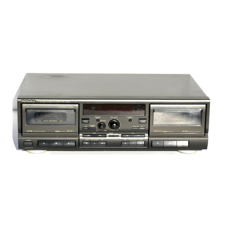
Technics RS-TR575M2 User manual

Technics

Technics RS-TR575M2 User manual

Technics RS-TR575 User manual

Technics

Technics RS-TR575 User manual
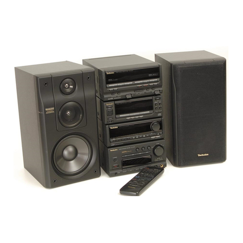
Technics RS-BX747 User manual

Technics

Technics RS-BX747 User manual

Technics RS-B605 User manual

Technics

Technics RS-B605 User manual

Technics RS-CH700 User manual

Technics

Technics RS-CH700 User manual
Technics RS-BX828 User manual

Technics

Technics RS-BX828 User manual

Technics RS-BX646 User manual

Technics

Technics RS-BX646 User manual

Technics RS-M235X User manual

Technics

Technics RS-M235X User manual

Technics RS-CA01 User manual

Technics

Technics RS-CA01 User manual

Technics RS-TR474 User manual

Technics

Technics RS-TR474 User manual

Technics RS-TR575 User manual

Technics

Technics RS-TR575 User manual

Technics RS-TR474 User manual

Technics

Technics RS-TR474 User manual

Technics RS-EH60 User manual

Technics

Technics RS-EH60 User manual

Technics RS-DC10 User manual

Technics

Technics RS-DC10 User manual

Technics RS-TR252 User manual

Technics

Technics RS-TR252 User manual

Technics RS-B965 User manual

Technics

Technics RS-B965 User manual

Technics RSTR272 - DUAL CASS. RECORDER User manual
Technics

Technics RSTR272 - DUAL CASS. RECORDER User manual

Technics RS-M215 User manual

Technics

Technics RS-M215 User manual

Technics RS-M225 User manual

Technics

Technics RS-M225 User manual

Technics RS-D200 User manual

Technics

Technics RS-D200 User manual

Technics RS-DV250 User manual

Technics

Technics RS-DV250 User manual

Technics RS-M226 User manual

Technics

Technics RS-M226 User manual

Technics RS-TR575 User manual

Technics

Technics RS-TR575 User manual
Technics RS-B555 User manual

Technics

Technics RS-B555 User manual
Popular Cassette Player manuals by other brands

Ahuja CPA-360 Operation manual

Ahuja

Ahuja CPA-360 Operation manual

Sony Pressman TCS-60DV Specifications

Sony

Sony Pressman TCS-60DV Specifications

Philips AQ6485/14 Product information

Philips

Philips AQ6485/14 Product information

Sony TCM-200DV - Cassette Recorder operating instructions

Sony

Sony TCM-200DV - Cassette Recorder operating instructions

Nakamichi BX-300 Service manual

Nakamichi

Nakamichi BX-300 Service manual

Panasonic RQ-E25V operating instructions

Panasonic

Panasonic RQ-E25V operating instructions

Aiwa TP-VS535 operating instructions

Aiwa

Aiwa TP-VS535 operating instructions

Yamaha MT8X Operation manual

Yamaha

Yamaha MT8X Operation manual

Sherwood Newcastle D-480 operating instructions

Sherwood

Sherwood Newcastle D-480 operating instructions

Manta MA408 user manual

Manta

Manta MA408 user manual

GPO W0162B user guide

GPO

GPO W0162B user guide

Marantz CP230 Service manual

Marantz

Marantz CP230 Service manual

Sony HST-471 Service manual

Sony

Sony HST-471 Service manual

Sharp JC-AV1 Operation manual

Sharp

Sharp JC-AV1 Operation manual

Pioneer CT-W103 Service manual

Pioneer

Pioneer CT-W103 Service manual

Sony CFS-B15 - Am/fm Stereo Cassette Recorder operating instructions

Sony

Sony CFS-B15 - Am/fm Stereo Cassette Recorder operating instructions

Sony WMFS220 - Portable Sports AM/FM Cassette... operating instructions

Sony

Sony WMFS220 - Portable Sports AM/FM Cassette... operating instructions

Aiwa HS-TA21 operating instructions

Aiwa

Aiwa HS-TA21 operating instructions

manuals.online logo
manuals.online logoBrands
  • About & Mission
  • Contact us
  • Privacy Policy
  • Terms and Conditions

Copyright 2025 Manuals.Online. All Rights Reserved.

ORDER
NO.
ARD-8004036C
Service
Manual
Cassette
Deck
RS-M14
(
Silver
load
Black
Face
Metal
Tape
Compatible
Stereo
Cassette
Deck
with
Peak-Hold
FL
Meters,
Soft-Touch
Controls
and
Rewind
Auto-Play
Convenience
DO
[sacevavsrem)
This
is
the
Service
Manual
for
the
following
areas.
wees
For
all
European
areas
except
United
Kingdom.
s+
For
United
Kingdom.
cei
ass
For
Asia,
Latin
America,
Middle
East
and
Africa
areas.
Al
see
sires
For
Australia.
a
For
Asian
PX.
naib
ants
For
European
PX.
RS-M24
MECHANISM
SERIES
Specifications
Track
system:
4-track
2-channel
stereo
recording
and
playback
Outputs:
LINE;
output
level
420
mV,
output
impedance
Tape
speed:
4.8cm/s
1.5kQ
or
less,
load
impedance
22kQ
over
Wow
and
flutter:
0.05%
(WRMS),
+0.14%
(DIN)
oh
output
level
80mV,
load
imped-
;
2
ance
Prequeney
esponces
Metal
Tapes
oe
na
+
(DIN)
Rec/Pb
connection:
5P
DIN
type;
CrOo/Fe-Cr
tape:
20-18
000Hz
input
sensitivity
0.25
mV,
impedance
5.3kQ
:
pe;
3016
O00Hz
(DIN)
output
level
420
mV,
impedance
5.2kQ
Normal
tape:
20—17,000Hz
Bias
frequency:
80
kHz
30—15,000Hz
(DIN)
Motor:
Electrical
DC
governor
motor
Signal-to-noise
ratio:
Dolby
NR
in;
67
dB
(above
5kHz)
Heads
:
2-head
system;
1-MX
head
for
record/playback
Dolby
NR
out:
57
dB
(signal
level=max.
record-
i
disubiecera
tents
heatl
tov
amseults
ing
level,
Fe-Cr/CrOz
type
tape)
Fast
forward
and
Power
requirements:
AC;
110/125/220/240V,
50-60Hz
rewind
time:
Approx.
90
seconds
with
C-60
cassette
tape
Power
consumption:
15
W
(for
European
areas
and
Australia)
Inputs:
MIC;
sensitivity
0.25
mV,
input
impedance
25kQ
13
W
(for
Asia,
Latin
America,
Middle
East,
Africa
over
applicable
microphone
impedance
4002—
areas
and
PX.)
Dimensions:
43,0cm(W)
X
11.9cm(H)
x
24.6cm(D)
LINE;
sensitivity
60mV,
input
impedance
40kQ2
Weight:
4.3kg
Specifications
are
subject
to
change
without
notice.
*
‘Dolby’
and
the
double-D
symbol
are
trademarks
of
Dolby
Laboratories.
@
Panasonic
Tokyo
ec
|
2
1CS
Matsushita
Electric
Industrial
Co.,
Ltd.
Matsushita
Electric
Trading
Co.,
Ltd.
17-15,
6-chome,
Shinbashi,
Minato-ku,
Tokyo
105
Japan
P.O.
Box
288,
Central
Osaka
Japan
RS-M14
CONTENTS
ITEM
|
PAGE
LOCATION
OF
CONTROLS
AND
COMPONENTS
certsssttestresteteeteeteeteceestectecteetaeenseeseesenes
{
DISASSEMBLY
INSTRUCTIONS
ssses:sstionncasnicastansanenaesainenes
esiguaiuy
tant
mete
aeniawasrenecatanenens
aie
2
DISASSEMBLY
NOTES
(MECHANISM
UNIT)
ccccccssrsscreeteeeceeceeetseeccteceessesecceseeeenseresseeas
3
ASSEMBLY
INSTRUCTIONS:
se:
s2ssssee2sssais
coscsssnasgencmeseersanancs
sas
anos
cemncmemonscemaeananmaeacneas
4
ADJUSTMENT
PARTS
LOGATION:
st0:3sscncesscnsentnsnaansisaweiosnamemicnioninnleemadey
enahG
ules
weneamerelnor
5
MEASUREMENT
AND
ADJUSTMENT
METHODS
cevecccrccesteeteceeeteceeeeceeetecsesseeeeeeeeeeeseens
6
ELECTRICAL
PARTS
LOCATIONicecssisectivctieniges
suniecierseadmesdpenruien
saumemes
Nace
sarteeatsins
dwar
aumneta
nents
8
SCHEMATIC
DIAGRAM
i
aetiwnnesimnrewswansnaniaeieis
dafaites
son
teaismesines
sales
enmebebc@uarmsacdcos@hessunntunlnenes
9
WIRING
CONNECTION
DIAGRAM
AND
CIRCUIT
BOARDS
'::+erseccereeceeceeteecenteeeeeeeaeeneees
10
EXPLODED:
VIEWS
sitatiasiccotsssnssaadicaine
sesasn
anions
seam
agicuadatltianinemeiusnbpiinedanaetnaanmrameasnedensawen
11
MECHAMICAL
PARTS.
LGGATION.
ssseseswizssech
caasecaqnessetagatinns
dhep
ease
baieiaiescmeaninsesmenanaec
sanaes
11
CABINE
TH
PARTS
sssanesgccnaeasciscdt
a
Mn
wats
smote
cats
Turisiaenats
sol
aismutatn
dete
aieloaamobmnainainewinaeatian’
dels
13
LOCATION
OF
CONTROLS
AND
COMPONENTS
@
Power
switch
@
Cassette
holder
@®
_
Headphones
jack
@
Eject
button
®
Record
button
©
Rewind/review
button
@
Fast
forward/cue
button
Playback
button
@
Stop
button
Pause
button
@
Input
selector
@
Dolby
noise-reduction
switch
@)
Tape
selector
(tape
select-normal/Fe-Cr/CrO2/metal)
Record
muting
button
@®
Input
level
controls
Tape
counter
and
reset
button
@
Record
indication
lamp
FL
(fluorescent
level)
meter
Microphone
jacks
@
Line
output
jacks
@)
Record/playback
connection
socket
@
Line
input
jacks
@
Voltage
selector
RS-M14
DISASSEMBLY
INSTRUCTIONS
*
The
head
azimuth
can
be
adjusted
by
removing
the
(C)
cassette
lid.
To
remove
——
. :
|
Shown
in
fig.
——.
Case
cover
°
4
screws
3
—
Bottom
cover
°
3
screws
*
2
control
knobs
Front
panel
°
Cassette
lid
°
4
screws
WwW]
ks
&
ol
°
4
red
screws
°
Tape
select
knob
*
3
push
buttons
°
4
screws
Main
circuit
board
¢
Cassette
holder
°
2
black
screws
¢
4
screws
Chassis
cover
assembly
and
mechanism
unit
CO}INNNINNN®D
Operation
button
assembly
°
2
screws
RS-M14
DISASSEMBLY
NOTES
©
Precautions
for
removal
of
the
motor
When
removing
the
motor,
follow
the
procedure
given
below.
1.
Remove
screw
(A),
and
then
detach
flywheel
retainer
(M44)
by
pulling
it
in
the
direction
of
the
arrow
as
in
fig.
9.
2.
After
removing
screws
(B),
detach
takeup
belt
(M78)
and
capstan
belt
(M76),
and
then
sub
chassis
assembly
(M72)
can
be
rernoved.
(fig.
9,
10)
3.
When
screws
(C)
is
removed
after
detaching
fast
forward
belt
(M77),
motor
assembly
(M71)
can
be
removed.
(fig.
10)
Fast
Forward
Belt(M77)
Screw(C)
Sez"
2
|
iy
ee
Tews
Sub
Chassis
Assembly
(M72)
Fig.
10
©
Head
base
plate
(M57)
and
upper
base
plate
(M83)
removing
procedure
1.
With
screw
(D)
removed,
head
base
plate
pressure
spring
(M66)
can
be
detached.
In
this
case,
take
care
not
to
lose
steel
ball
(M65).
(fig.
11)
2.
With
head
release
spring
(M68)
removed,
head
base
plate
(M57)
can
be
detached.
(fig.
11,
12)
In
this
case,
take
care
not
to
lose
steel
ball
(M65)
and
roller
(M64).
3.
After
removing
pressure
roller
release
spring
(M25),
remove
pressure
roller
assembly
(M40).
(fig.
12)
4,
Remove
screw
(E),
and
then
upper
base
plate
(M83)
can
be
detached.
(fig.
12)
(MECHANISM
UNIT)
Sub
Chassis
Assembly
(M72)
Takeup
Belt
(M78)
Screw
(A)
Capstan
Belt
(M76)
/
Flywheel
Retainer(M44)
;
Flywheel
a
1
Retaimer
(m44)—
|
1
!
|
|
|
!
1
|
|
I
|
|
!
Head
Base
Plate
Pressure
Spring(M66)
Head
Base
Plate(M57)
|
Screw(D)
Steel
Ball(M65)
Head
Release
Spring(M68)
Fig.
11
Steel
Ball(M65)
Roller(M64)
Pressure
Roller
Release
Spring
(M25)
Upper
Base
Plate(M83)
Screw(E)
Pressure
Roller
Assembly
(M40)
Fig.
12
MECHANISM
SECTION
1.
For
repair,
measurement
or
adjustment
with
the
mechanism
removed
from
the
unit
be
sure
to
ground
the
lower
base
plate
of
the
mechanism.
2.
For
grounding,
connect
a
extension
cord
to
the
mechanism's
lower
base
plate
and
the
Lug
terminal
from
main
circuit
board.
3.
Without
grounding,
the
amplifier
does
not
operate
properly.
Fig.
13
ASSEMBLY
INSTRUCTIONS
;
Capstan
Belt
(M76)
e
Belt
mounting
Fast
Forward
Belt
(M77)
Takeup
Belt
(M78)
Check
that
each
belt
is
free
of
damage
or
grease
on
the
surface,
after
that,
set
the
belt
as
illustrated,
and
mount
it
on
the
lower
base
plate
(M84)
after
that,
set
the
takeup
belt
(M78)
on
the
fast
forward
connection
pulley
assembly
(M82).
é
Fig.
14
@
Positioning
the
takeup
reel
table
assembly
1
RS
dakodties
Detection
Lever
M50:
Takeup
Reel
When
installing
the
takeup
reel
table
assembly,
be
sure
to
Table
Assembly
mount
the
auto-stop
friction
hub
(shown
in
fig.
16),
as
illustrated
in
fig.
15.
If
the
takeup
reel
table
is
positioned
incorrectly
at
any
place
other
than
that
shown
in
fig.
15,
the
auto-stop
mechanism
remains
operative
at
all
times.
Auto-Stop
Auto-Sto
. .
i
Pp
Friction
Hub
Friction
Hub
Fig.
16
@
How
to
install
the
flywheel
retainer
PAS
WAS
REbAIRE
1.
Insert
the
thrust
retainer
into
the
hole
@)
of
the
flywheel
Hole
®
retainer
as
shown
in
fig.
17.
2.
Hold
the
thrust
retainer
with
the
thumb
as
shown
in
;
fig.
18.
GS
)
Thrust
Retainer
Flywheel
Hold
this
part
with
the
thumb
Fig.
17
Fig.
18
3.
Engage
the
parts
@)
and
©
of
the
flywheel
retainer
with
the
lower
base
plate
as
shown
in
fig.
19.
4.
Shift
down
the
flywheel
retainer,
supported
at
points
©,
in
the
direction
of
the
arrow
as
illustrated.
(fig.
20)
5.
Attach
the
screw
(A)
in
the
position
as
shown
in
fig.
9.
e
Mounting
the
operation
button
assembly
Before
mounting
the
operation
button
assembly
on
the
mechanism
body,
be
sure
to
lift
the
main
control
lever
in
the
direction
of
the
arrow
using
a
screwdriver,
as
shown
in
fig.
21,
until
it
locks
in
place.
M8:
Main
Control
Lever
Hub
of
the
Playback
Button
Assembly.
Screwdriver
If
it
is
not
mounted
in
this
manner,
the
hub
of
the
playback
—
button
assembly
during
playback
catches
on
the
main
control
lever,
making
it
impossible
to
release
playback
mode.
Spt
eOM
EET
ON
Meaty
Fig.
21
Tape
Speed
Adjustment
VR.
TP3
TP4
TP2 TP5 TP6
TP8~
TP7
VR7
VR8&
TPl
L2
L1
VR6
tp
ii.
%
i
\
R6
6)
/
ee
poe
ra
Ss
TP9
TP10
/
TP12
4
R62!
VR5
VR402
VR1
VR2
VR401
NY
F
5
Fig.
22
MEASUREMENT
AND
ADJUSTMENT
METHODS
NOTES:
Keep
good
condition,
set
lever
switches
and
controls
in
the
following
positions,
unless
otherwise
specified.
@
Make
sure
heads
are
clean.
@
Make
sure
capstan
and
pressure
roller
are
clean.
©
Judgeable
room
temperature:
20-£5°C
(68+9°F)
e
Dolby
NR
switch:
OUT
ITEM
MEASUREMENT
&
ADJUSTMENT
®
Head
position
adjustment
Condition:
*
Playback
and
pause
mode
®
Head
azimuth
adjustment
Condition:
*
Playback
mode
Equipment:
*VTVM
—
*
Oscilloscope
*
Test
tape
(azimuth)
---QZZCFM
*
Test
tape
(tape
path
viewer)
@
Tape
speed
Condition:
*
Playback
mode
Equipment:
*
Digital
electronic
counter
or
frequency
counter
*
Test
tape
---
QZZCWAT
“2.
Playback
this
tape.
®
Tape
selector:
Normal
position
@
Input
selector:
Line
in
@
Input
level
controls:
Maximum
Screw
(A)
—
Head
Adjusting
Plate
Capstan
)
(B)
4
Pressure
Roller
(The
head
adjusting
plate
is
provided
to
adjust
the
tape
touch
of
the
head
in
cue
or
review
mode.)
1.
Press
the
playback
button
and
pause
button.
2.
Measure
the
space
between
the
pinch
roller
and
the
capstan.
Standard
value:
0.5+0.3mm
Space
(adjustable)
3.
If
the
measured
value
is
not
within
the
standard
value,
untighten
screw
(A),
and
slide
the
head
adjusting
plate
in
the
direction
of
arrow
(B)
for
adjustment.
Record/playback
head
azimuth
adjustment
1.
Test
equipment
connection
is
shown
in
fig.
24.
2.
Playback
azimuth
tape
(QZZCFM
8
kHz).
3.
Adjust
record/playback
head
angle
adjustment
screw
(B)
LINE
OUT
Playback
mode
VTVM
Oscilloscope
in
fig.
25
so
that
output
level
at
LINE
OUT
becomes
“*™*
Fig.
24
maximum.
4.
Measure
both
channels,
and
adjust
levels
for
equal
output.
5.
After
adjustment
lock
head
adjustment
screw
with
lacquer.
Record/playback
mode
Erase
head
Erase
head
azimuth
adjustment
1.
Test
equipment
connection
is
the
same
above
but
use
the
tape
path
viewer
(QZZCRD)
instead
of
test
tape
(QZZCFM).
fh
fe
(B)
Fig.
25
Fig.
26
3.
Adjust
screw
(C)
shown
in
fig.
26
so
that
the
tape
may
not
get
curled
or
malformed
by
tape
guide
of
the
erase
head.
.
After
adjustment,
lock
head
adjust
screw
with
lacquer.
Tape
speed
accuracy
1.
Test
equipment
connection
is
shown
in
fig.
27.
2.
Playback
test
tape
(QZZCWAT
3,000Hz),
and
supply
playback
signal
to
frequency
counter.
3.
Measure
this
frequency.
4.
On
the
basis
of
3,000Hz,
determine
value
by
following
formula:
Test
tape
Playback
mode
Digital
electronic
counter
Fig.
27
f
—
3,000
3,000
.
Take
measurement
at
middle
section
of
tape.
Tape
speed
accuracy
=
x
100(%)
where,
f=
measured
value
Standard
value:
1.5%
Adjustment
method
1.
Playback
the
test
tape
(middle).
2.
Adjust
so
that
frequency
becomes
3,000
Hz.
3.
Tape
speed
adjustment
VR
shown
in
fig.
22.
ITEM
MEASUREMENT
&
ADJUSTMENT
®
Playback
frequency
response
Condition:
*
Playback
mode
*
Tape
selector
~
++»Normal
position
Equipment:
*VTVM
—
*
Oscilloscope
*
Test
tape---
QZZCFM
@
Playback
gain
Condition:
*
Playback
mode
*
Tape
selector
---
Normal
position
Equipment:
*VTVM
—
*
Oscilloscope
*
Test
tape---
QZZCFM
Tape
speed
fluctuation
Make
measurements
in
same
manner
as
above
(beginning,
middle
and
end
of
tape),
and
determine
the
difference
between
maximum
and
minimum
values
and
calculate
as
follows:
f=
F2_
5
100
(96)
—————
f1=maximum
value,
f2
=
minimum
value
3,000
Tape
speed
fluctuation
=
Standard
value:
Less
than
1%
Note:
Please
use
non
metal
type
screwdriver
when
you
adjust
tape
speed
accuracy
on
this
unit.
Pe
Playback
frequency
response
chart
12.5kHz
1.
Test
equipment
connection
is
shown
in
fig.
24.
2.
Place
UNIT
into
playback
mode.
3.
Playback
the
frequency
response
test
tape
(QZZCFM).
.
Measure
output
level
at
315Hz,
12.5kHz,
8kHz, 4kHz,
1kHz,
250Hz,
125Hz
and
63
Hz,
and
compare
each
output
level
with
the
standard
frequency
315
Hz,
at
LINE
OUT.
.
Make
measurement
for
both
channels.
.
Make
sure
that
the
measured
value
is
within
the
range
specified
in
the
frequency
response
chart.
63Hz
125Hz
200Hz
500Hz
1KHz
500Hz
1kHz
Fig.
28
63Hz125Hz
200
Hz
.
Test
equipment
connection
is
shown
in
fig.
24.
.
Playback
standard
recording
level
portion
on
test
tape
(QZZCFM
315Hz),
and
using
VT
VM
measure
the
output
level
at
LINE
OUT.
.
Make
measurement
for
both
channels.
|
Standard
value:
around
0.39V
Adjustment
1.
If
measured
value
is
not
within
standard,
adjust
VR1
(L-CH),
VR2
(R-CH)
(See
fig.
22
on
page
5).
2.
After
adjustment,
check
“Playback
frequency
response”
again.
@
Bias
leakage
Condition:
*
Record
mode
*
Input
level
controls
---
MAX
*
Tape
selector
--»
Metal
position
Equipment:
*VTVM
—
*
Oscilloscope
@
Erase
current
Condition:
*
Record
mode
*
Tape
selector
--»
Metal
position
Equipment:
*VTVM
—
*
Oscilloscope
1.
Test
equipment
connection
is
shown
in
fig.
29.
page
2.
Place
UNIT
into
record
mode.
3.
Adjust
trap
coil
L1
(L-CH),
L2
(R-CH)
so
that
measured
value
on
VTVM
becomes
minimum.
4.
Take
adjustment
for
both
channels.
TPS(L-CH)
Record
/playback
head
Record
mode
Fig.
29
Vtvm_
Oscilloscope
1.
Test
equipment
connection
is
shown
in
fig.
30.
2.
Press
the
record
and
pause
buttons.
3.
Set
the
tape
selector
to
metal
position.
4.
Read
voltage
on
VT
VM
and
calculate
erase
current
by
following
formula:
Erase
head
Voltage
across
both
ends
of
R301
1(Q)
Era
rrent
(A)
=
VIVM
Oscillos
se
curre
t
(
)
VTVM
Oscilloscope
Fig.
30
Standard
value:
155+15mA
(Metal
position)
|
5.
If
measured
value
is
not
within
standard,
adjust
as
follows.
Adjustment
1.
Open
the
point
(A)
and
short
the
point
(B)
on
the
main
circuit
board
in
the
wiring
connection
diagram
(See
page
10).
Ee
he
ae
ITEM
MEASUREMENT
&
ADJUSTMENT
2.
Make
measurement
for
erase
current.
3.
Make
sure
that
the
measured
value
is
within
the
erase
current
of
140mA
to
170
mA.
4.
lf
it
is
beyond
the
value,
carry
out
the
following
adjustments:
@®
Bias
current
Condition:
*
Record
mode
*
Tape
selector
--
Normal
position
--Fe-Cr
position
--CrOz
position
--
Metal
position
Equipment:
*VTVM
*
Oscilloscope
@
Overall
gain
Condition:
*
Record/playback
mode
*
Input
level
controls
---
MAX
*
Standard
input
level;
MIC
+++++++-
—72+4dB
LINE
IN---
—-2444dB
Equipment:
*VTVM
*
AF
oscillator
*
ATT
*
Oscilloscope
*
Resistor
(600
2)
*
Test
tape
(reference
blank
tape)
--QZZCRA
for
Normal
®
Overall
frequency
response
Condition:
*
Record/playback
mode
*
Tape
selector
--
Normal
position
--Fe-Cr
position
--CrO2
position
--
Metal
position
*
Input
level
controls
---
MAX
Equipment:
*VTVM
*
AF
oscillator
*
ATT
*
Oscilloscope
*
Resistor
(600
2)
*
Test
tape
(reference
blank
tape)
--QZZCRA
for
Normal
--QZZCRY
for
Fe-Cr
--QZZCRX
for
CrOz
--QZZCRZ
for
Metal
.
Test
equipment
connection
is
shown
in
fig.
31.
.
Place
UNIT
into
record
mode,
and
tape
selector
to
normal
.
Read
voltage
on
VT
VM
and
calculate
bias
current
by
4
3;
6
Note:
Before
measuring
and
adjusting,
make
sure
of
the
playback
frequency
response
(For
the
.
Place
UNIT
into
record
mode,
and
tape
selector
to
normal
p
°
If
the
erase
current
is
less
than
140
mA,
short
the
point
(A).
°
If
the
erase
current
is
more
than
170mA,
open
the
points
(A)
and
(B).
VR7
(L-CH)
VR8
(R-CH)
oa
Record/playback
head
position.
Record
mode
TP1(L-CH)
;
TP2IR-CH)
R1
(L-CH)
R2
(R-CH)
following
formula:
Value
read
on
VTVM
(V)
VTVM_
Oscilloscope
10
(Q)
Bias
current
(A)
=
Fig.
31
Standard
value:
around
410A
(Normal
position)
:
.
If
measured
value
is
not
within
standard,
adjust
VR7
(L-CH)
and
VR8
(R-CH)
(See
fig.
22
on
page
5).
Set
the
tape
selector
to
each
position.
.
Make
sure
that
the
measured
value
is
within
standard.
Standard
value:
around
440A
(Fe-Cr
position),
around
545A
(CrO2
position),
around
800A
(Metal
position)
est
equipment
connection
is
shown
in
fig.
32.
Kasnitiaiies
head
i
osition.
.
Supply
1kHz
signal
(—24dB)
from
AF
oscillator,
through
ATT
to
LINE
IN.
djust
ATT
until
monitor
level
at
LINE
OUT
becomes
Record/playback
39V.
head
Record
mode
Test
tape
AF
oscillator
A
0.
.
Using
test
tape,
make
recording.
.
Playback
recorded
tape,
and
make
sure
-
value
at
LINE
—7
dB).
.
If
measured
value
is
not
0.39
V,
adjust
VR5
(L-CH),
VR6
(R-CH)
(See
fig.
22
on
page
5).
.
Repeat
from
step
(2).
Playback
mode
yTVM
Oscilloscope
Fig.
32
OUT
on
VTVM
becomes
0.39
V
(
Test
tape
Overall
frequency
response
chart
(Normal)
10kHz
seit
100s
640
Hz
2kHz
4kHz
method
of
measurement,
please
refer
to
the
playback
frequency
response).
1.
2.
3.
.
Supply
1kHz
signal
from
AF
oscillator
.
Record
each
frequency
1
kHz,
50Hz,
Test
equipment
connection
is
shown
in
fig.
32.
Place
the
normal
test
tape
(QZZCRA)
in
the
cassette
holder.
Place
UNIT
into
record
mode,
and
tape
selector
to
normal
position.
:
100Hz
Fig,
Hz
2kHz
33
50Hz
Overall
ee
response
chart
(Fe-Cr,
CrO2,
Metal)
2kHz
12kHz
through
ATT
to
LINE
IN.
200
Hz
640
Hz
.
Adjust
ATT
so
that
input
level
is
—20dB
below
standard
recording
level
(standard
recording
level=0
VU).
.
At
this
time,
LINE
OUT
level
indicates
0.039V.
200
Hz.
640
Hz
200Hz,
4kHz,
8kHz
and
10kHz
(12kHz
Fig.
34
for
Fe-Cr,
CrOz
and
metal).
mee
50Hz
.
Playback
and
express
in
dB
the
difference
between
‘plavbaek
output
level
of
each
frequency
based
on
playback
output
level
of
1
kHz.
.
Make
sure
that
the
measured
value
is
within
the
range
specified
in
the
overall
frequency
response
chart
(Shown
in
fig.
33).
.
Change
test
tape
to
Fe-Cr
(QZZCRY),
CrO2
(QZZCRX)
and
metal
(QZZCRZ).
.
Set
the
tape
selector
to
each
position.
.
Measure
in
the
same
manner
from
step
(3)
to
step
(8).
.
Make
sure
that
the
measured
value
is
within
the
range
specified
in
the
overall
frequency
response
chart
for
Fe-Cr,
CrO2
and
metal
tape
(Shown
in
fig.
34).
Adjustment
—
Using
bias
current
1.
When
the
frequency
response
between
the
middle
and
high
frequency
range
becomes
higher
than
the
standard
value,
as
*
shown
by
the
solid
line
in
fig.
35’
increase,
refer
to
bias
current
adjustment.
.
When
it
becomes
lower,
as
shown
by
dotted
line,
refer
to
bias
current
adjustment.
Note:
For
the
method
of
bias
current
measurement,
refer
to
“Bias
current
adjustment”
on
page
8.
1kHz
=
2kHz
;
8kHz
12kHz
@
Fluorescent
meter
.
Test
equipment
connection
is
shown
in
fig.
32.
Condition:
.
As
shown
in‘tig.
36,
connecting
the
base
of
Q402
and
*
Record
mode
ground
stops
the
oscillation
of
the
astable
multivibrator
*
Input
level
controls
---
MAX
comprising
Q402
and
Q403.
*
Tape
selector
.
Supply
1kHz
signal
(—24
dB)
to
the
LINE
IN
then
press
.--
Normal
position
the
record
button.
.
Adjust
the
ATT
so
that
the
output
level
at
LINE
OUT
becomes
0.39V
(The
input
level
at
this
condition
is
termed
the
standard
input
level).
.
Adjustment
at
“—20
dB”:
A.
Adjust
the
ATT
so
that
the
input
level
is
—20dB
below
standard
recording
level.
ao
B.
Adjust
VR401
so
that
the
—20dB
segment
at
ights
up
in
the
~200.8dB
range
(L-CH
—.
SU/IIIMIUIIIIIIIIIIIIIIIIIIIIIIUIIUI1111111111HIHI1
only)
(See
fig.
37).
ray
.
Adjustment
at
“OdB”:
2
6+
4°25
0
2
00
+66
A.
Adjust
the
ATT
so
that
the
output
level
at
Fig.
37
LINE
OUT
becomes
0.39
V.
ei
scence
(The
input
level
at
this
condition
is
termed
MYTYTETTYYT
TTY
=
(+108)
the
standard
input
level.)
STMT
UU
MT
.
Adjust
VR402
so
that
the
+1dB
segment
a;
el
a
oe
ak
an
lights
up
in
the
O+0.2dB
range
of
the
pan
lhe
abated
standard
input
level
(See
fig.
38).
":
.
Repeat
twice
between
steps
(5)
and
(6)
above.
Mmm
ccc
cece
.
Adjust
ATT
and
check
that
all
segments
lights
shaven
asuaaaviasiauiatas
Sarasa
up
when
an
input
signal
level
is
increased
to
STILT
ATLA
UU
10
dB
higher
than
the
standard
input
level
(See
20
PEAK)
6
*
42+
20
2
(«6
8»
(1048)
Equipment:
*VTVM
—
*
AF
oscillator
*
ATT
*
Resistor
(600Q)
@
Dolby
NR
circuit
.
Test
equipment
connection
is
shown
in
fig.
40.
Condition:
.
Place
UNIT
into
record
mode,
set
the
Dolby
NR
switch
*
Record
mode
to
OUT
position
and
supply
to
LINE
IN
to
obtain
*
Dolby
NR
switch
---
IN/OUT
—34.5dB
at
TP11
(L-CH),
TP12
(R-CH)
(frequency
cron
TPL
CH)
*
Input
level
controls
---
MAX
5kHz).
ae
ea
.
Confirm
that
the
value
at
IN
position
is
8(+2.5)dB
LINE
IN
[X
(ieee
Equipment:
se
Q
fee
aa
ter
than
the
value
at
OUT
position
of
Dolby
NR
1
*VTVM
+
AF
oscillator
a.
P
y
SOL
OOOO
OQ.
*
ATT
*
Oscilloscope
:
AF
oscillator
ATT
Record
mode
©
VTVM
*
Resistor
(600
Q)
Fig.
40