manuals.online logo
Brands
  1. Home
  2. •
  3. Brands
  4. •
  5. Technics
  6. •
  7. Computer Hardware
  8. •
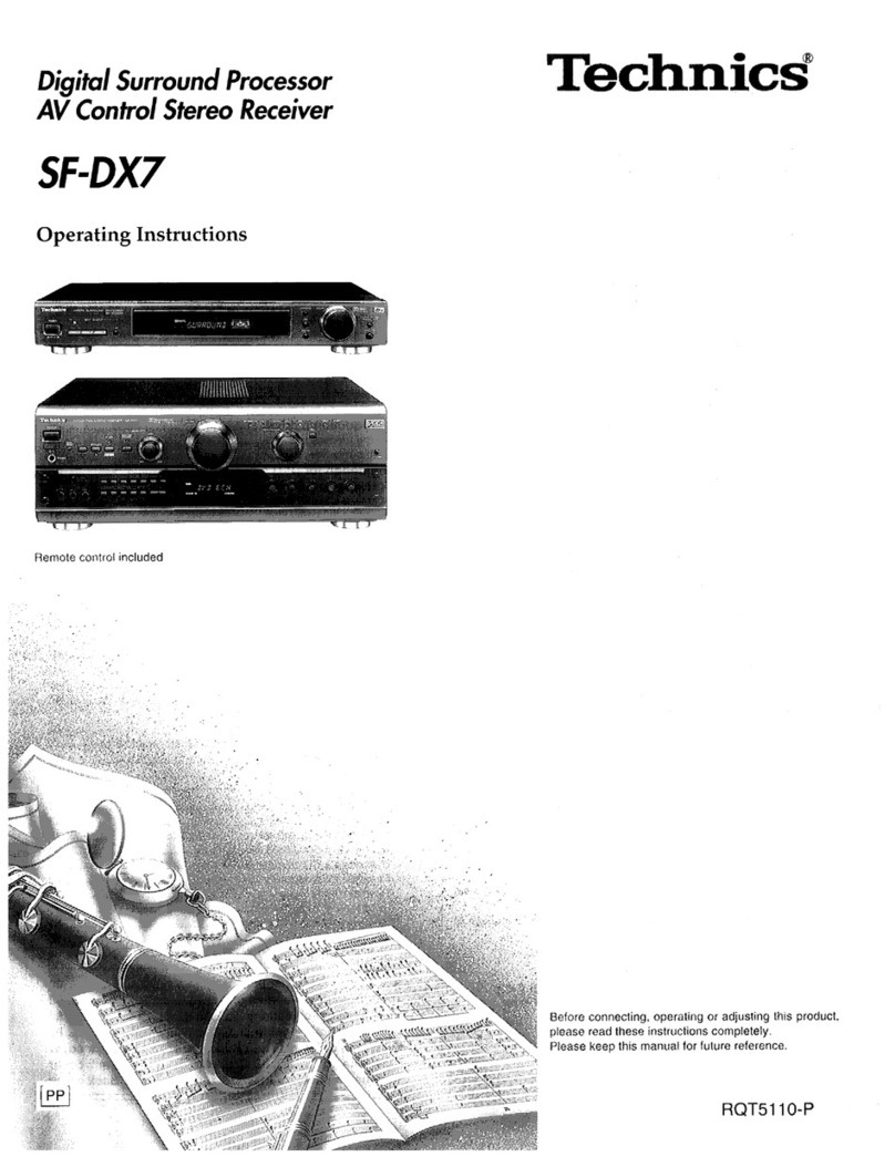
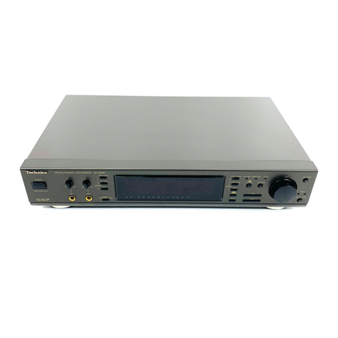
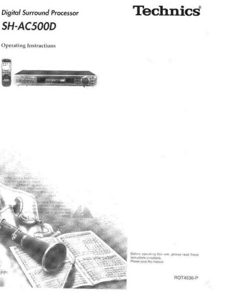
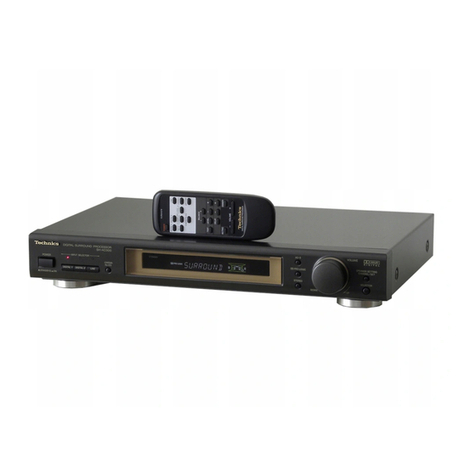
  9. Technics SH-AC500D User manual

Technics SH-AC500D User manual

ORDER
NO.
MD9905090C2
Service
Manual
Digital
Surround
Processor
Processor
DIGITAL
D[ecsvsunouns]
DUfor]
Prey
H-AC500D
Colour
(WK)
aacan
Black
Type
Area
Guten)
wea
|
cour
Manufactured
under
license
from
Dolby
Laboratories.
“DOLBY”,
“Pro
Logic”
and
the
double-D
symbol
are
trademarks
of
Dolby
Laboratories.
Confidential
Unpublished
Works.
©
1992-1997
Dolby
Laboratories,
Inc.
All
rights
reserved.
DTS
Inc.
USP
No.
5,
451,
942.
Specifications
AUDIO
Total
harmonic
distortion
Frequency
response
FRONT
L/R
(1
kHz,
0
dB,
PCM)
0.007%
FRONT
L/R,
CENTER,
SURROUND
L/R
(LARGE)
Dynamic
range
96
dB
20
Hz-20
kHz,+1dB
S/N
(IHF-A)
100
dB
Outlet
voltage/Impedance
2
V
(at0
dB)/1
kQ
~~
Load
impedance
More
than
10
kQ
Input
impedance
LINE
22kQ
H
GENERAL
COAXIAL
75
kQ
Power
supply
AC
230
-
240
V,
50
Hz
Delay
time
Power
consumption
18W
DOLBY
DIGITAL
Dimensions
(W
X H X
D)
430
X
69.4
X
301.4
mm
CENTER
O0-5ms_
Weight
2.6
kg
SURROUND
L/R
0-15
ms
DOLBY
PRO
LOGIC
Notes
:
SURROUND
L/R
15-30ms
_
Specifications
are
subject
to
change
without
notice.
Weight
and
dimensions
are
approximate.
A,
WARNING
This
service
information
is
designed
for
experienced
repair
technicians
only
and
is
not
designed
for
use
by
the
general
public.
It
does
not
contain
warnings
or
cautions
to
advise
non-technical
individuals
of
potential
dangers
in
attempting
to
service
a
product.
Products
powered
by
electricity
should
be
serviced
or
repaired
only
by
experienced
professional
technicians.
Any
attempt
to
service
or
repair
the
product
or
producis
dealt
with
in
this
service
information
by
anyone
else
could
result
in
serious
injury
or
death.
©
1999
Matsushita
Electronics
(S)
Pte.
Lid.
=
go
All
rights
reserved.
Unauthorized
copying
ec
nics
and
distribution
is
a
violation
of
law.
SH-AC500D
|
i
Contents
PAGE
©,
ACCESSORIES
vicsicciwecetiinesesshastecdeaadear
tact
stieenaetenaee
2
e
CAUTIONS
FOR
AC
MAINS
LEAD...........
eee
3
e
FRONT
PANEL
CONTROLS
............cccccceeeecccceeeeeeeeeees
4
©
CONNECTIONS
uuu...
eceececeeecceccecceceececeeseecaaeseeeecesenee
5~7
«
(SPEAKER
SET
TIN
Giwtecrseeccesthexxted
oc
ecrtsaciesnedis
aveets
8
e
SPEAKER
OUTPUT
ADJUSTMENTS
...........c
eee
9~10
e
DELAY
TIME
ADJUSTMENTS
.............cccccceeeseeeseeeeeeee
1
e
ENJOYING
SOUND
IN
A
VARIETY
OF
REPRODUCTION
MODES.
.........ccccceeceeeeeeseeeeeeeeeeeeaeee
12~13
©
OTHER
FUNCTIONS
2.00.0...
cece
csseseececcnseseeseseeneeneeeee
14
e
REMOTE
CONTROL
QUICK
REFERENCE
..............
15
©
OPERATION
CHECKS
.........ccccccceeceneeseccssecensesereenseenee
16~17
Mi
Accessories
e
TERMINAL
FUNCTION
OF
IC’S
e
TYPE
ILLUSTRATION
OF
IC’S,
TRANSISTORS
AND
DIODES
e
BLOCK
DIAGRAM
e
SCHEMATIC
DIAGRAM
e
PRINTED
CIRCUIT
BOARD
e
CABINET
PARTS
LOCATION
e
REPLACEMENT
PARTS
LIST
e
RESISTORS
&
CAPACITORS
e
PACKING
MATERIALS
&
ACCESSORIES.
................
©
PACKAGING
uu...
eee
AC
power
supply
cord
for
United
Kingdom
Optical-fiber
cable
;
(eal.
ties
==
ES
=)
AC
power
supply
cord
for
Others
Remote
control
unit
Monaural
connection
cables
Batteries
Stereo
connection
cables
@
Caution
for
AC
Mains
Lead
(For
“EB”
area
code
model
only.)
For
your
safety,
please
read
the
following
text
carefully.
This
appliance
is
supplied
with
a
moulded
three
pin
mains
plug
for
your
safety
and
convenience.
A
5-ampere
fuse
is
fitted
in
this
plug.
Should
the
fuse
need
to
be
replaced
please
ensure
that
the
replacement
fuse
has
a
rating
of
5-ampere
and
that
itis
approved
by
ASTA
or
BSI
to
BS1362.
Check
for
the
ASTA
mark
<>
or
the
BSI
mark
@
on
the
body
of
the
fuse.
If
the
plug
contains
a
removable
fuse
cover
you
must
ensure
that
it
is
refitted
when
the
fuse
is
replaced.
If
you
lose
the
fuse
cover,
the
plug
must
not
be
used
until
a
replacement
cover
is
obtained.
A
replacement
fuse
cover
can
be
purchased
from
your
local
dealer.
CAUTION
!
IF
THE
FITTED
MOULDED
PLUG
IS
UNSUITABLE
FOR
THE
SOCKET
OUTLET
IN
YOUR
HOME
THEN
THE
FUSE
SHOULD
BE
REMOVED
AND
THE
PLUG
CUT
OFF
AND
DISPOSED
OFF
SAFELY.
THERE
IS
A
DANGER
OF
SEVERE
ELECTRICAL
SHOCK
IF
THE
CUT
OFF
PLUG
IS
INSERTED
INTO
ANY
13-AMPERE
SOCKET.
If
a
new
plug
is
to
be
fitted,
please
observe
the
wiring
code
as
shown
below.
If
in
any
doubt
please
consult
a
qualified
electrician.
IMPORTANT
The
wires
in
this
mains
lead
are
coloured
in
accordance
with
the
following
code:
Blue:
Neutral
Brown:
Live
As
these
colours
may
not
correspond
with
the
coloured
markings
identifying
the
terminals
in
your
plug,
proceed
as
follows:
The
wire
which
is
coloured
Blue
must
be
connected
to
the
terminal
which
is
marked
with
the
letter
N
or
coloured
Black
or
Blue.
The
wire
which
is
coloured
Brown
must
be
connected
to
the
terminal
which
is
marked
with
the
letter
L
or
coloured
Brown
or
Red.
WARNING:
DO
NOT
CONNECT
EITHER
WIRE
TO
THE
EARTH
TERMINAL
WHICH
IS
MARKED
WITH
THE
LETTER
E,
BY
THE
EARTH
SYMBOL
—
OR
COLOURED
GREEN
OR
GREEN/YELLOW.
THIS
PLUG
IS
NOT
WATERPROOF—KEEP
DRY.
SH-AC500D
Before
use
Remove
the
connector
cover.
How
to
replace
the
fuse
The
location
of
the
fuse
differ
according
to
the
type
of
AC
mains
plug
(figures
A
and
B).
Confirm
the
AC
mains
plug
fitted
and
follow
the
instructions
below.
Illustrations
may
differ
from
actual
AC
mains
plug.
1.
Open
the
fuse
cover
with
a
screwdriver.
Figure
A
7
Figure
B
2.
Replace
the
fuse
and
close
or
attach
the
fuse
cover.
Figure
A
Fuse
(5
ampere)
OS
Figure
B
Fuse
(5
ampere)
SH-AC5O0D
|
i
Front
panel
controls
ers
eegate
vere
ni
BEN
cematinee
er
Bee
ester
eceerntmana
econ
sence
on:
g
A
RRA
ELLIO
ORME
eG
RERUN
etal)
nt
Naar
nn
i
Yr
NERENE
DHRR
HECHT
Ee
SR
RARER
Aiea
mieten
pet
anR
eRe
AOS
NEEIAD
oieitaL
CO
#29
Loic,
Sb
POS
PEO
DE
AOE
TRAVIAN
SYNE
PRL
NMA
SRI
2
PSSA
AS
SRNR
ILO
UUO
MTN ERA
HORII
Control
section
Zl
@
Unit
on/off
button(
a
©
=
cbf)
and
remote
standby
indicator
(¢/))
,
Use
this
button
to
turn
the
unit
on
and
off.
BZ
(off):
The
unit
is
in
standby
mode.
-=.
(on):
The
unit
is
on.
The
unit
can
be
turned
on
and
off
with
the
remote
control.
When
the
unit
is
turned
off
with
the
remote
control
it
is
in
remote
standby
and
the
indicator
lights.
The
unit
is
still
using
a
smali
amount
of
power
in
the
standby
and
remote
standby
conditions.
Standby
uses
less
power.
When
the
unit
is
connected
to
the
AC
mains
lead,
this
indicator
lights
up
in
standby
mode
and
goes
out
when
the
unit
is
turned
on.
@
Input
select
buttons/indicators
(DIGITAL
1,
DIGITAL
2,
DIGITAL
3,
LINE)
@
Surround
mode
button
(SURROUND)
@
Digital
Theater
Systems
mode
button
(DTS)
©
Stereo
mode
button
(STEREO)
©
Volume
control
(VOLUME)
Main
unit
oni
@
Speaker
setting
buttons
(CHANNEL/SET,
SELECTOR)
@®
Dynamic
range
compression
button
(DR
COMP)
@
Balance
control
(L,
R)
(©
Output
level
setting
buttons
(TEST,
LEVEL,
-,
+)
@
Delay
time
setting
buttons
(DELAY,
-,
+)
(2
Dimmer
button
(DIMMER)
(3
Muting
button
(MUTING)
|
Display
section
E]
(@
Surround
format
indicators
(OU
DIGITAL,
E233,
OO
PRO
LOGIC)
@
Display
(®
Dynamic
range
compression
indicator
(DR
COMP)
@
Speaker
indicators
Light
in
accordance
with
the
speaker
setting,
and
each
of
the
indicators
corresponding
with
the
speaker
concerned
flashes
when;
e
the
type
or
presence
of
that
speaker
is
set,
e
the
test
signal
is
output
from
that
speaker,
e
the
output
level
or
delay
time
of
that
speaker
is
adjusted.
18
Signal
format
indicators
(LS,
C,
RS,
L,
R,
S,
LFE)
These
indicators
light
up
to
indicate
the
Dolby
Digital
or
DTS
input
signal
format.
LS:
Surround
speaker
(left)
C:
Center
speaker
RS:
Surround
speaker
(right)
L:
Front
speaker
(left)
R:
Front
speaker
(right)
“S"
represents
the
mono
surround
and
“LFE”
(Low
Frequency
Effect)
is
a
channel
for
the
deep-bass
effect
in
the
low
frequency
range.
SH-AC500D
Hi
Connections
Before
proceeding
with
the
connections,
ensure
that
the
power
to
S
:
bi
all
the
units
has
been
turned
off.
tereo
connection
cable
Connect
the
AC
power
supply
cord
only
after
all
other
cables
and
aU
is
=
>on.
cords
are
connected.
Red
(R)
Connection
to
a
receiver
or
amplifier
Connection
to
a
receiver
(or
amplifier}
with
6
channel
discrete
input
terminals
|
Sa
efs00)9)
DIGITAL(O0
DIGITAL/DTS/PCM)
D©
©,O}
[li
©
(o
©)
POO
DIGITAL
1
OIGITAL2
=
DIGITAL
3.
FRONT
SUBWOOFER
SURROUND
Stereo
connection
cables
(included)
os
Monaural
connection
cables
(included)
Receiver
or
amplifier
(This
illustration
is
an
example
of
connection
from
this
unit
to
a
model
SA-AX720
receiver.)
DV
pee
DVD/6CH
=
SUBWOOFER
SURROUND
R
foo)
(oO)
0
©
eal
(XO)
10)
10)
10)
©00
SEQ
Oo
SEQ
Oo
For
your
reference:
The
position
and
labeling
of
terminals
differs
with
the
receiver
(or
amplifier).
The
“DVD/DVD
6
CH”
terminal
in
the
above
illustration,
for
example,
is
often
labeled
as
“FRONT
(L,
R).”
SH-ACSOOD
|
|
Connections
for
outputting
the
6
channel
signals
through
3
power
amplifiers
]
This
illustration
is
an
example
of
connection
from
this
unit
to
a
stereo
control
amplifier
of
model
SU-C1000
and
three
stereo
power
amplifiers
of
model
SE-A1000.
SH-ACS00D
DIGITAL(Q9
DIGITAL/DTS/PCM)
JO
Dg
©
DIGITA,
QIGITAL2
—
DIGITAL
|LBWOOFER
LINE
‘SURROUND
IN
Stereo
connection
cable
(not
inculuded)
Stereo
connection
cables
(inculuded)
Control
amplifier
(not
included)
PREOUT
oaao
oooo0.0
0
0
O
o
00
Fj
00
Co
er
Monaural
connection
cables
(included)
For
your
reference:
If
three
integrated
amplifiers
are
connected
instead
of
the
power
amplifiers,
it
is
not
necessary
to
connect
a
stereo
control
amplifier.
Connect
the
output
terminals
of
this
Stereo
power
Stereo
power
unit
to
the
See
input
terminals
of
the
amplifier
for
aia.
ai
integrated
amplifiers.
center
speaker
:
INPUT
INPUT
(got
included
INPUT
speakers
or
LINE
IN
or
LINE
IN
)
or
LINEIN
|
(not
included)
Stereo
power
amplifier
for
front
(L,
R)
speakers
(not
included)
WW
1777
WA
1472
1
000
ome)
——
WW
1777
WW
1477
WA
17747
WW
1777
CI
600
one)
jm
oxon@)
[ome)
CS
___
a
Se
Front
speaker
(not
included)
INPUT
or
LINE
IN
Front
speaker
(not
included)
Subwoofer
built-in
Center
speaker
amplifier
(not
included)
(not
included)
Surround
speaker
(ny,
(not
included)
Surround
speaker
(not
included)
|
SH-AC500D
Connections
to
audio-visual
equipment
and
the
AC
power
cord
Sak
Nesayols)
Pata
mDaTALDTEFCM
1G)
6)
CENT
PO©
20
FRONT
SUBWOOFER
SURROUND
j}
FRONT
“6|O*_.©
Oa
©
Oa
SUBWOOFER
SURROUND
Optical-fiber
Optical-fiber
cable
cable
(not
included)
(included)
Coaxial
cable
(not
included)
DIGITAL
OUT
DVD
player,
etc.
(not
included)
Connection
for
optical-fiber
cable
Dust-protection
cap
©
Do
not
bend
the
optical-fiber
cable
at
a
sharp
angle.
@
If
the
digital
optical
connector
is
not
going
to
be
used,
be
sure
to
attach
the
dust-protection
cap
to
prevent
exposure
to
dust.
“DIGITAL
1”
terminals
8
Disconnect
the
coaxial
cable
from
the
DIGITAL
1
terminal
when
using
an
optical
fiber
cable.
Only
the
coaxial
cable
is
recognized
if
both
types
are
connected.
Coaxial
cable
(not
included)
DIGITAL
OUT
AC
power
supply
cord
(included)
4)
Household
AC
outlet
:
(AC
120
V/60
Hz)
DIGITAL
OUT
Other
digital
playback
sources
(laser
disc
players,
etc.)
“LINE
IN”
terminals
(Only
if
a
control
amplitier
has
not
been
connected.)
You
can
connect
a
set-top
box
tuner
for
digital
television
or
similar
decoder.
If
“LINE”
is
selected
with
the
input
selector
on
this
unit,
the
signals
received
through
these
terminals
are
output
as
they
are
without
passing
through
any
sound
control
circuits
(i.e.
no
volume
or
other
sound
adjustments
can
be
made
with
this
unit.)
@
Dolby
Digital
RF
(radio
frequency)
signals
cannot
be
decoded
with
this
unit
even
if
a
unit
that
has
Dolby
Digital
RF
output
terminals
is
connected
to
this
unit.
Turn
off
the
power
to
this
unit
if
unusual
hissing
or
beat
sounds
are
heard
while
listening
to
FM,
AM,
or
television
broadcasts.
SH-AC500D
li
Speaker
setting
Set
the
types
and
presence
of
the
speakers
before
enjoying
the
sound
by
reproducing
the
input
source.
Before
proceeding:
Check
the
frequency
range
of
each
speaker
to
be
used.
Consider
speakers
capable
of
playing
back
low
frequency
sounds
(below
around
100
Hz)
as
LARGE.
Consider
speakers
not
capable
of
playing
back
low
frequency
sounds
as
SMALL.
Press
POWER.
owaon
Press
CHANNEL/SET,
and
select
the
channel
for
which
the
speaker
is
to
be
set.
becoescucccavceconvesoen
wepececococvevecerossgsn0e
Keene
Bevecseosvocensceace
Each
time
the
button
is
pressed,
the
channel
display
is
SPEAKER
SETTING
switched
in
the
listed
order.
CHANNEUSET
FRONT:
Front
speakers
CENTER:
Center
speaker
SURROUND:
Surround
speaker
SUB-WFR:
Subwoofer
COMPLETE:
Select
this
when
you
have
completed
the
settings.
The
selected
channel
is
shown
on
the
display
for
approx.
2
seconds.
The
current
setting
for
that
channel
is
then
shown
as
a
flashing
display.
The
indicator
corresponding
to
the
selected
speaker
also
continues
to
flash.
Press
SELECTOR,
and
set
the
type
(LARGE,
SMALL)
and
presence
(YES,
NO
or
NONE)
of
the
speaker.
Each
time
the
button
is
pressed,
the
display
is
switched
in
the
listed
order.
LARGE:
select
if
the
speaker
can
produce
low
frequency
sounds,
SMALL:
select
if
the
speaker
cannot
produce
low
frequency
sounds,
NONE:
select
if
you
are
not
using
a
center
speaker
or
surround
speakers,
YES:
select
if
you
are
using
a
subwoofer,
NO:
select
if
you
are
not
using
a
subwoofer.
The
sound
for
speaker
channels
that
are
set
to
“NONE”
or
“NO”
are
output
from
the
front
speakers.
DTS
format
software,
however,
depends
upon
all
channels
being
operable,
and
so
the
sound
for
speakers
not
connected
is
not
heard
at
all,
no
matter
what
settings
are
made.
SELECTOR
Repeat
steps
2
and
3
to
complete
the
settings
\
for
all
the
channels.
Press
CHANNEL/SET
to
select
“COMPLETE”.
(FRONT)|
LARGE
SMALL
The
settings
are
now
entered
into
the
unit’s
memory.
The
display
goes
out
after
about
2
seconds
and
the
previous
(CENTER)
|
LARGE
NONE
display
reappears.
The
speaker
indicators
light
up
unless
“NONE”
or
“NO”
has
been
selected
for
the
corresponding
channel.
(SURROUND)
[LARGE
|—-[SMALL}—-[
NONE
]}
[Ee
If
no
buttons
are
pressed
for
approx.
10
seconds
during
the
setting
process,
ail
previous
settings
are
canceled,
the
setting
mode
is
SUB-WER
released,
and
the
original
display
is
restored.
(
)
YES
NO
Begin
the
setting
process
again
if
this
occurs.
For
your
reference:
The
setting
remains
as
it
is
until
changed
by
the
above
procedure,
even
after
the
power
has
been
turned
off.
SH-AC500D
li
Speaker
output
adjustments
Set
the
initial
output
level
first,
then
proceed
to
adjust
the
output
level
for
each
speaker
channel.
|
Setting
the
initial
volume
level
When
this
unit
is
connected
to
a
receiver
(or
amplifier)
that
has
6
channel!
discrete
input
terminals:
Set
the
volume
level
to
0
dB
using
this
unit’s
VOLUME
control.
Set
the
volume
control
of
the
receiver
(or
amplifier)
to
the
position
normally
used
for
yf
.
#4
enjoying
the
source.
If
the
test
signal,
described
below
in
“Speaker
output
adjustment”,
is
too
soft,
adjust
the
volume
on
the
receiver
(or
amplifier).
If
the
input
level
to
the
receiver
(or
amplifier)
is
too
loud,
lower
the
volume
level
using
this
unit’s
VOLUME
control.
When
this unit
is
connected
to
three
standard
stereo
amplifiers:
Set
the
volume
level
to
around
-48
dB
using
this
unit’s
VOLUME
control.
Ej
(If
this
unit
is
connected
to
three
integrated
amplifiers:)
owen
Set
the
volume
control
of
the
integrated
amplifiers
to
the
position
normally
used
for
enjoying
the
source.
If
the
test
signal,
described
below
in
“Speaker
output
adjustment’,
is
too
soft
or
too
loud,
adjust
the
volume
on
this
unit.
Adjust
the
output
level
of
each
speaker
G@intatkecntmlmen
Use
the
test
signal
to
adjust
the
output
level
of
the
center
speaker,
surround
speakers
and
subwoofer.
MUTING
CO)
VOLUME
CO
Note]
ae
|
ae
If
the
output
from
the
front
speakers
is
unbalanced,
make
balance
adjustments
on
the
receiver
or
amplifier
before
continuing
with
the
following.
(Refer
to
the
instruction
manual
of
the
component.)
If
the
receiver
or
amplifier
cannot
be
used
to
make
balance
adjustments,
they
can
be
made
on
this
unit.
Press
SURROUND
to
select
the
surround
mode.
“SURROUND?”
appears
on
the
display.
(Continued
on
next
page)
SURROUND
‘
SH-AC500D
BALANCE
DIGITAL? DIGITAL2
DIGITA3
LINE
=
VOLUME
+
Center
position
Press
TEST
to
output
the
test
signal.
“TEST”
appears
on
the
display,
and
the
speaker
indicator
corresponding
to
the
speaker
whose
outputting
sound
flashes.
The
test
signal
is
automatically
output
from
each
speaker
for
2
seconds
in
the
following
sequence:
c
c>R->
Boba
ey
L:
Front
speaker
(left)
C:
Center
speaker
R:
Front
speaker
(right)
RS:
Surround
speaker
(right)
LS:
Surround
speaker
(left)
SW:
Subwoofer
(Speakers
for
which
NONE
or
NO
has
been
set
are
skipped.)
lf
the
left
and
right
front
speaker
balance
is
poor,
do
not
proceed
with
the
next
step
until
balance
has
been
improved
with
the
procedure
described
below
(4).
Press
LEVEL
to
select
the
speaker
channel
to
adjust.
The
output
level
appears
on
the
display,
and
the
speaker
indicator
for
the
selected
speaker
flashes.
Each
time
the
button
is
subsequently
pressed,
the
speaker
whose
level
is
to
be
set
is
selected
in
the
listed
sequence.
(Speakers
for
which
NONE
or
NO
has
been
set
are
skipped.)
6!
Press
LEVEL
[-]
or
[+]
to
adjust
the
output
level.
Channels
C,
RS,
LS,
and
SW
can
be
adjusted
between
-12
dB
and
+12
dB.
Set
them
so
that
the
output
from
each
channel
appears
to
be
the
same
as
that
from
the
front
speakers.
Repeat
steps
5
and
6
to
adjust
the
output
of
each
channel
to
approximately
the
same
apparent
level.
To
stop
the
test
signal
Press
TEST.
Using
this
unit
to
adjust
the
balance
of
the
left
and
right
front
speakers
ZI
Make
the
adjustments
while
listening
to
the
test
signa!
put’
out
in
step
4
above.
Press
BALANCE
[L]
or
[R]
on
the
remote
control
to
adjust
the
level
balance.
The
left/right
balance
appears
on
the
display.
Each
time
the
button
is
subsequently
pressed,
the
output
level
of
the
front
speaker
opposite
to
the
button
pressed
is
decreased.
(i.e.
when
the
L
button
is
pressed,
the
output
level
of
the
R
speaker
is
decreased.)
The
original
display
is
restored
if
a
button
isn’t
pressed
for
4
or
more
seconds.
The
balance
of
the
surround
speakers
cannot
be
adjusted
using
the
BALANCE
buttons.
==
10:
i
Delay
time
adjustments
DIGITAL?
LINE
S
rn
Cotto)
SURROUND
Center
speaker
Front
Front
speaker
5
speaker
Surround
speaker
Surround
speaker
=
44
—
SH-AC500D
By
adjusting
the
delay
time,
the
difference
in
the
distance
from
the
viewing
and
listening
position
to
the
front
speakers
and
the
distance
to
the
center
speaker
and
surround
speakers
can
be
offset
and
made
equal.
This
achieves
better
sound
localization
and
makes
a
more
life-like
reproduction
of
the
sound
field
possible.
Remote
control
only
Press
SURROUND
to
select
the
surround
mode.
“SURROUND?”
appears
on
the
display.
Press
DELAY
to
select
the
channel
to
be
adjusted.
Each
time
the
button
is
subsequently
pressed,
the
channel
whose
delay
time
is
to
be
set
is
selected
alternately:
C
(Center
speaker)
«—
S
(Surround
speakers)
For
each
channel,
the
delay
time
is
displayed,
and
the
speaker
indicator
for
the
corresponding
speaker
flashes.
The
display
is
restored
if
a
button
isn’t
pressed
for
4
or
more
seconds.
Speakers
for
which
NONE
has
been
set
are
skipped.
Press
[-]
or
[+]
to
set
the
delay
time.
When
the
button
is
pressed,
the
current
delay
time
is
displayed.
Each
time
the
button
is
pressed,
the
delay
time
will
change.
The
delay
time
increments
are
different
depending
on
the
speaker
as
follows.
Speaker
Available
delay
time
setting
(ms)
Center
0,
1,
2,
3,
4,5
Surround
0,5,
10,
15
Please
note
the
following
if
delay
time
is
adjusted
while
playing
back
a
source:
Adjustment
is
not
possible
if
the
source
is
DTS
format.
While
the
DM
PRO
LOGIC
indicator
is
alight,
the
center
channel
cannot
be
adjusted
and
15
ms
are
added
to
the
delay
times
listed
for
the
surround
channel
when
displayed.
To
calculate
the
delay
time
EN
D::
Distance
from
front
speaker
Dz:
Distance
from
surround
speaker
Ds:
Distance
from
center
speaker
Setting
the
center
channel
delay
time:
Set
to
0
ms
{f
Ds
less
than
Di
Increase
1
ms
for
every
30
cm
(1
feet)
of
difference
between
D:
and
Ds
Setting
the
surround
channel
delay
time:
If
D1
is
equal
to
or
Set
to
0
ms
tess
than
Dz
P
Start
at
0
ms
and
increase
by
5
ms
for
Mile
Steee
isan
every
1.5
m
(5
feet)
of
difference
between
D:
and
Dz
If
Di
is
equal
to
or
less
than
Ds
SH-AC500D
|
li
Enjoying
sound
in
a
variety
of
reproduction
modes
INPUT
SELECTOR
° ° °
DIGITAL
1]
DIGITAL
2}
DIGITAL
3
SURROUND
This
unit
enables
sound
to
be
enjoyed
in
three
reproduction
modes
-
SURROUND,
DTS
and
STEREO.
Press
POWER.
Turn
on
the
power
to
the
other
AV
components
as
well.
Press
one
of
the
input
select
buttons
to
select
the
input
source.
The
indicator
above
the
pressed
bution
now
lights.
DIGITAL
1:
Selects
the
source
connected
to
the
DIGITAL
1
terminal.
The
unit
automatically
recognizes
whether
the
source
is
connected
through
the
optical
fiber
cable
or
the
coaxial
cable.
lf
both
types
are
connected
at
the
same
time,
only
the
coaxial
cable
is
recognized.
Disconnect
the
coaxial
cable
if
the
external
unit
is
connected
with
the
optical
fiber
cable.
DIGITAL
2:
Selects
the
source
connected
to
this
terminal.
DIGITAL
3:
Selects
the
source
connected
to
this
terminal.
LINE:
Selects
the
source
connected
to
the
LINE
terminal.
If
a
control
amp
has
been
connected
to
the
LINE
terminal,
select
the
input
source
on
it
as
well.
When
DIGITAL
1,
2
or
3
has
been
selected:
The
reproduction
modes
in
step
3
can
be
selected.
When
LINE
has
been
selected:
The
analog
sound
signals
input
through
LINE
IN
terminals
are
directy
output
to
the
left
and
right
front
speakers
via
the
connected
component.
“THROUGH”
appears
on
the
display.
Only
the
POWER
button
and
select
buttons
function
when
LINE
has
been
selected.
Press
SURROUND,
DTS
or
STEREO
to
select
the
reproduction
mode.
The
selected
reproduction
mode
appears
on
the
display
(=
see
the
previous
page
for
descriptions
of
the
modes.)
(When
this
unit
is
connected
to
a
receiver
(or
amplifier)
that
6
channel
discrete
input
terminais:)
Set
the
receiver
(or
amplifier)
to
the
6
channel
discrete
input
mode.
If
this unit
is
connected
to
three
integrated
amplifiers,
set
the
input
selector
on
the
amplifiers
to
the
connected
input
terminal
such
as
the
“AUX”
terminals.
(Refer
to
the
instruction
manuals
of
the
components.)
(Continued
on
next
page)
ae,
SH-AC500D
Start
playing
the
sound
source.
The
surround
indicators
@)
DO
DIGITAL:
Lights
if
the
source
is
Dolby
Digital
Format.
©
GZS:
Lights
if
the
source
is
DTS
format.
©
OO
PROLOGIC:
Lights
when
Dolby
Surround
parts
of
Dolby
Digital
format
software
are
played
back,
or
when
playing
audio
CDs
in
the
SURROUND
mode.
eOnly
Dolby
Digital,
DTS
or
PCM
signals
>
can
be
(a)
[
oa
DIGITAL
S
‘
reproduced.
The
digital
input
signal
of
sampling
frequencies
96
kHz
and
other
signal
formats
such
as
MPEG
cannnot
be
reproduced
on
this
unit.
fats]
+
j
tei
eWhen
playback
is
started,
the
sound
may
be
cut
or
i
i
interrupted
before
the
input
source
is
confirmed
as
Dolby
Digital
or
DTS.
Gd
viata
*
PCM
signal:
This
refers
to
the
recording
format
of
signals
(44.1
kHz,
linear
16
bits)
used
for
audio
CDs
[PRO
Loic
6!
Adjust
the
volume.
Set
the
volume
on
the
receiver
(or
amplifier)
and
this unit
to
the
initial
level.
Any
subsequent
volume
adjustments
VOLUME
should
be
done
as
follows.
[A
(When
this
unit
is
connected
to
a
receiver
(or
amplifier)
that
has
6
channel
discrete
input
terminals:)
Adjust
the
volume
using
the
volume
\ y
DOWN
control
on
the
receiver
(or
amplifier).
If
input
to
the
receiver
(or
amplifier)
is
excessive,
reduce
the
volume
on
this
unit
slightly.
‘B|
(When
this
unit
is
connected
to
three
standard
stereo
amplifiers
or
three
integrated
amplifiers:)
Adjust
the
volume
using
this
unit’s
VOLUME
control.
To
adjust
the
volume
of
the
components
connected
to
the
stereo
control
amplifier,
use
the
volume
control
on
the
stereo
control
amplifier.
After
use
Reduce
the
volume
on
the
component
you
are
using
to
contro!
the
volume
(the
receiver,
amplifier
or
this
unit)
to
the
minimum
level,
then
turn
off
the
power
to
this
unit
and
the
other
components.
as
43
SH-AC500D
|
@
Other
functions
DIGITAL!
OIGITAL2 DIGITAL3
LINE
SURROUND
DTS.
STEREO
OR
COMP:
BALANCE
Oc
lS
SOO
DELAY
—
+
COCO
f=}
MUTING
Ca
=e
a
DR
COMP
Dynamic
range
compression
indicator
Gd
odiaitAaL
MUTING
DIMMER
Setting
the
midnight
mode
(dynamic
range
compression)
“Dynamic
range
compression”
(DR
COMP)
is
a
function
for
compressing
the
dynamic
range
(reproduction
level
range)
of
audio
signals.
It
is
used
for
viewing
movie
software
late
at
night
or
at
other
times
when
high
volume
levels
are
not
desirable.
This
function
only
works
with
DR
COMP
compatible
Dolby
Digital
format
software.
Remote
control
onl
Press
DR
COMP.
ZI
The
“DR
COMP?”
indicator
lights.
When
the
button
is
pressed
again,
the
function
is
released,
and
the
indicator
goes
off.
For
your
reference:
When
DR
COMP
is
on,
scenes
that
already
have
a
low
sound
level
will
be
heard
as
they
are.
When
scenes
that
are
loud
occur,
the
function
acts
to
reduce
the
peak
level.
The
sound
field
will
remain
intact
even
if
DR
COMP
is
functioning.
Muting
the
sound
temporarily
oS
Remote
control
onl
Press
MUTING.
&
During
muting,
the
message
“MUTING
ON
NOW”
scrolls
across
the
display.
When
the
button
is
pressed
again,
the
original
volume
level
is
restored.
When
the
unit’s
power
is
switched
off,
muting
is
canceled.
Selecting
the
display
panel
brightness
ee
Remote
control
only.
Press
DIMMER.
The
display
panel
is
dimmed.
When
the
button
is
pressed
again,
or
when
the
unit’s
power
is
switched
off,
the
original
brightness
is
restored.
=
fq
-
+
=
VOLUME
+
ee,
DIGITAL)
DIGITAL?
DIGITAL3
LINE
SURROUNC
DTS.
DELAY
=
=
-
VOLUME
=
+
a
li
Remote
control
quick
reference
SH-AC500D
Functions
which
are
also
available
from
the
main
unit
To
turn
the
unit
ON/OFF
Selecting
the
input
source
DIGITAL
1
DIGITAL2
DIGITAL3
LINE
oS
(ah
Ge
Gh
Selecting
the
SURROUND
reproduction
mode
SURROUND
-+———
Selecting
the
DTS
reproduction
mode
fee
Selecting
the
STEREO
reproduction
mode
Adjusting
the
volume
To
turn
on
the
midnight
mode
Adjusting
the
volume
balance
between
the
left
and
right
front
speakers
STEREO
Functions
which
are
only
available
from
the
remote
control
DR
COMP
BALANCE
L
R
JC)
Outputting
the
test
signal
to
adjust
the
output
level
of
each
speaker
Selecting
the
speaker
channel
and
adjusting
its
output
level
C9
Selecting
the
speaker
channel
and
adjusting
its
delay
time
DELAY
Muting
the
sound
temporarily
——
MUTING
Selecting
the
display
pane!
brightness
a
DIMMER
SH-ACS500D
|
li
Operation
Checks
"ATTENTION
SERVICER"
Some
chassis
components
may
have
sharp
edges.
Be
careful
when
disassembling
and
servicing.
1.
This
section
describes
procedures
for
checking
the
operation
of
the
major
printed
circuit
boards
and
replacing
the
main
components.
2.
For
reassembly
after
operation
checks
or
replacement,
reverse
the
respective
procedures.
Special
reassembly
procedures
are
described
only
when
required.
3.
Select
items
from
the
following
index
when
checks
or
replacement
are
required.
°
Contents
page
e
Checking
Procedure
For
Each
Major
P.C.B.
.....cssssccssssscsseeceeseesseeesseeeeesoeseneneesenseoesesssoueneuseneerssenesenesneeesnenereeas
16~17
@
Checking
Procedure
For
Each
Major
P.C.B.
1.
Checking
of
the
Control,
Display,
Volume
and
Power
Switch
P.C.B.
Remove
the
top
cabinet.
Display
P.C.B.
(Solder
Side)
Control
P.C.B.
Volume
P.C.B.
(Solder
Side)
(Solder
Side)
Claw
®
Power
Switch
P.C.B.
(Solder
Side)
Release
the
two
rear
claw
and
pull
out
the
back
panel
(3)
mm>
®
fim
b
[SNE2129-1]
[XTBS3+8JFZ1]
(Black)
(Black)
es
FG
SH-AC500D
2.
Checking
of
the
AC-3
Module
Unit,
Display,
Sub-Transformer,
;
ivvay)
[XTBS3+8JFZ1]
Digital
Input
and
Main
P.C.B.
Lb
(Black)
[XTB3+20JFZ]
(Farm
o
2
Sub-Transformer
P.C.B.
(Component
side)
Flip
over
the
Main
PC.B.
following
the
arrow
direction.
Main
P.C.B.
(Component
side)
Main
P.C.B.
(Solder
side)
Digital
Input
P.C.B.
(Solder
side)
AC-3
Module
Unit
P.C.B.
(Solder
side)
Sub-Transformer
P.C.B.
(Solder
side)
Remove
the
shield
from
AC-3
Module
Unit
P.C.B.
ry
ee
SH-AC500D
|
@
Terminal
Functions
Of
ICs
e
1C901
(M38B53M4057F)
System
Microprocessor
.
Mark
VO
Function
hs
Mark
vo
Function
1
XCS
O
|
Key
Input
1
~
2
41~56|
SEG1~SEG16
|
O
|
FL
digit
signal
output
2
SK
O
|
Thermal/Over
load
input
1
57
INIT
|
|
Diode
input
initial
settings
3
DI
O
|
Key
Input
4
58
-
|
|
Volume
control
output
(Down)
4
DO
|
|
Thermal/Over
load
input
2
59
PDN
O
|
Volume
control
output
(Up)
5~6
|
STB1~STB2
|
O
|
Stereo
signal
detect
terminal
60
OVLERR
|
|
REC
Mute
control
7~8
RA~RB
|
|
Wake
up
timer
LED
61
FRQO
|
|
Serial
data
signal
9
--
|_|
Control
of
RDS
IC
(ST)
stereo
signal
62
FRQ1
|
|
Power
limitter
control
output
10
RESET
|
|
Remote
control
terminal
63
AC3
|_|
Tuner
control
(CE)
chip
enable
signal
41
CK
O
|
Reset
detect
terminal
64
AUDIO
|_|
Selector/Tuner
(CK)
clock
signal
12
DATA
O
|
Control
of
RDS
IC
(Ck)
clock
signal
65
CCS
O
|
Selector/Tuner
(DT)
data
signal
13
vss
—
|
Control
of
RDS
IC
(DT)
data
signal
66
CCLK
O
|
Selector
control
terminal
14
XIN
--
|
GND
terminal
67
CDIN
O
|
MMD
control
terminal
15
XOUT
--
|
Crystal
oscillator
terminal
(
4
MHz
)
68
CDOUT
|_|
Surround
control
(CK)
clock
signal
16
VDD/VCC
--
|
Crystal
oscillator
terminal
(4
MHz
)
69
ss
O
|
Surround
control
(DT)
data
signal
17~18|
DIGITAL1~2
|
O
|
LED
driver
IC
(DT)
data
signal
70
SCK
O
|
Surround
control
(CE)
chip
enable
signal
19
LINE
O
|
SFC
mode
encoder
input
1
71
MOSI
O
|
GND
for
A-D
converter
20
STANDBY
|
O
|
SFC
mode
encoder
input
2
72
MISO
O
|
Reference
voltage
for
A-D
converter
21
|
POWERSW
| |
|
Selector
encoder
for
input
1
73
AVSS
—
|
SD
signal
detect
input
22
REMOTE
|
|
Blackout
detection
terminal
74
VREF
—
|
Encoder
of
surround
mode
selector
input1
23
HOLD
|
|
Selector
encoder
for
input
2
75
MRESET
O
|
Help
LED
control
output
24
POWER
O
|
VCR2
control
input
76
IFCD
|_|
Encoder
of
surround
mode
selector
input2
25~27|
A4053A~C
|
O
|
6ch
swcontrol
output
(ST)
77
TCS
O
|
Video
selector
control
output
A
28
VEE
--
|
Power
supply
for
FL
driver
78
TRST
O
|
Video
selector
control
output
B
29~30|
MUTEA/S
|
O
|
Speaker
B
control
output
79
KEY1
A/D|
Key
input
1
31~40|
DIG10~DIG1
|
O
|
Muting
control
output
80
KEY2
A/D|
Key
input
2
—
42
—
@
Type
Illustration
of
IC's,
Transistors
and
Diodes
SH-AC500D
a
=
is
—
M38B53M4057F
MX23C4000MC1
NJM4580DD
BR93LC46
TC9212P
TC9162AN
CS4926-CL
TC4052BP
CS4226-KQ
5
8
4
1
|
TC74VHC574FL
TC7SHU04F85L
NJM2060D
TC74VHC244FL
1
20
l
2SD1915FTA
2SD592AQSTA
2SA933SSTA
SLR325VCT31
RVD1SS133TA
LN846RPH
2SD1450RSTTA
2SA992FEPTA
2SC1740SSTA
2SB621AQSTA
RVTDTA114YST
RVTDTC114YST
é
Cathode
Anode
Anode
A
Cathode
Cathode
Ande
‘Os
‘
E
a
Cc
B
Bice
RL1N4003N02
MTZJ27DTA
MTZJ13BTA
ca
ca
MTZJ3R9ATA
cathese
Cathode
MTZJ4R7BTA
r
:
A
MTZJ6R2ATA
MTZJ6R2CTA
=
MEE
Anode
SH-ACS500D
|
I
Wiring
Connection
Diagram
[fe]
SuB-TRANSFORMER
P.C.B.
POWER
SWITCH
P.C.B.
D
F
pre
.
[eeneal
TRANSFORMER
COMPONENT
SIDE
[Pp]
CONTROL
P.c.B.
COMPONENT
SIDE
PT1
POWER
TRANSFORMER
ZY
main
P.c.s.
|
sunnouno
un
||
eden
Be
:
FRONT
L/R
“|
w901
JK402
SURROUND
L/R
[LINE
IN
|
IN
CENTER/
|
SUBWOOFER
ws04
JK401
1
CN902
CNg901
W301
|
FRONT
UR
COMPONENT
SIDE
COMPONENT
SIDE
FE}
DisPLay
p.c.B.
DIGITAL
INPUT
P.C.B.
ai
DIGITAL3
+
DIGITAL2
[LINE
IN]
IN
ee
|
oi
fe
dl
VOLUME
P.C.B.
CN1002
—-
CN1001
COMPONENT
SIDE
IF]
Ac-3
MODULE
UNIT
P.C.B.
COMPONENT
SIDE
sKoor|
|
COMPONENT
SIDE
—
20
—

Other manuals for SH-AC500D

3

Other Technics Computer Hardware manuals

Technics SH-AC500D User manual

Technics

Technics SH-AC500D User manual

Technics SH-9038 User manual

Technics

Technics SH-9038 User manual

Technics SH-AV22 User manual

Technics

Technics SH-AV22 User manual

Technics SH-AC300 User manual

Technics

Technics SH-AC300 User manual

Technics SY-EW03NX User manual

Technics

Technics SY-EW03NX User manual

Technics SF-DX7 User manual

Technics

Technics SF-DX7 User manual

Technics SY-EW04NX User manual

Technics

Technics SY-EW04NX User manual

Technics SH-GE90 User manual

Technics

Technics SH-GE90 User manual

Popular Computer Hardware manuals by other brands

Renesas GreenPAK SLG47115V quick start guide

Renesas

Renesas GreenPAK SLG47115V quick start guide

HP P Class 450/500/550/600/650/700/750 supplementary guide

HP

HP P Class 450/500/550/600/650/700/750 supplementary guide

HP MCS-200 user guide

HP

HP MCS-200 user guide

Victron energy VE.Bus BMS V2 product manual

Victron energy

Victron energy VE.Bus BMS V2 product manual

Precision Power PSC-221 owner's manual

Precision Power

Precision Power PSC-221 owner's manual

Renesas H8/3001 TFP-80C user manual

Renesas

Renesas H8/3001 TFP-80C user manual

OPTO 22 PCI-AC51 user guide

OPTO 22

OPTO 22 PCI-AC51 user guide

Sundrax DimGate DIN user manual

Sundrax

Sundrax DimGate DIN user manual

SeaLevel SIO-104 manual

SeaLevel

SeaLevel SIO-104 manual

Fujitsu Semiconductor Controller MB89950/950A Hardware manual

Fujitsu

Fujitsu Semiconductor Controller MB89950/950A Hardware manual

Supermicro AOC-SLG3-4X4P user guide

Supermicro

Supermicro AOC-SLG3-4X4P user guide

Intel SASMF8I - RAID Controller Hardware user's guide

Intel

Intel SASMF8I - RAID Controller Hardware user's guide

ORiNOCO PC Card Getting started guide

ORiNOCO

ORiNOCO PC Card Getting started guide

Nvidia GeForce2 Ti SP6600Ti manual

Nvidia

Nvidia GeForce2 Ti SP6600Ti manual

Cypress Semiconductor CY7C1302DV25 Specification sheet

Cypress Semiconductor

Cypress Semiconductor CY7C1302DV25 Specification sheet

Vecow PE-5000 Series user manual

Vecow

Vecow PE-5000 Series user manual

Omron 3G3AX-MX2-PRT-E user manual

Omron

Omron 3G3AX-MX2-PRT-E user manual

Anaheim Automation DPG10002-01 user guide

Anaheim Automation

Anaheim Automation DPG10002-01 user guide

manuals.online logo
manuals.online logoBrands
  • About & Mission
  • Contact us
  • Privacy Policy
  • Terms and Conditions

Copyright 2025 Manuals.Online. All Rights Reserved.