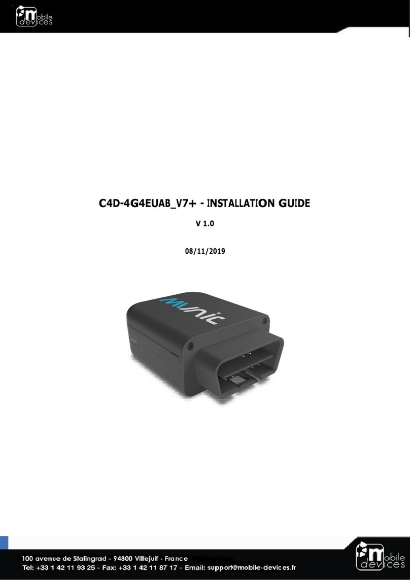
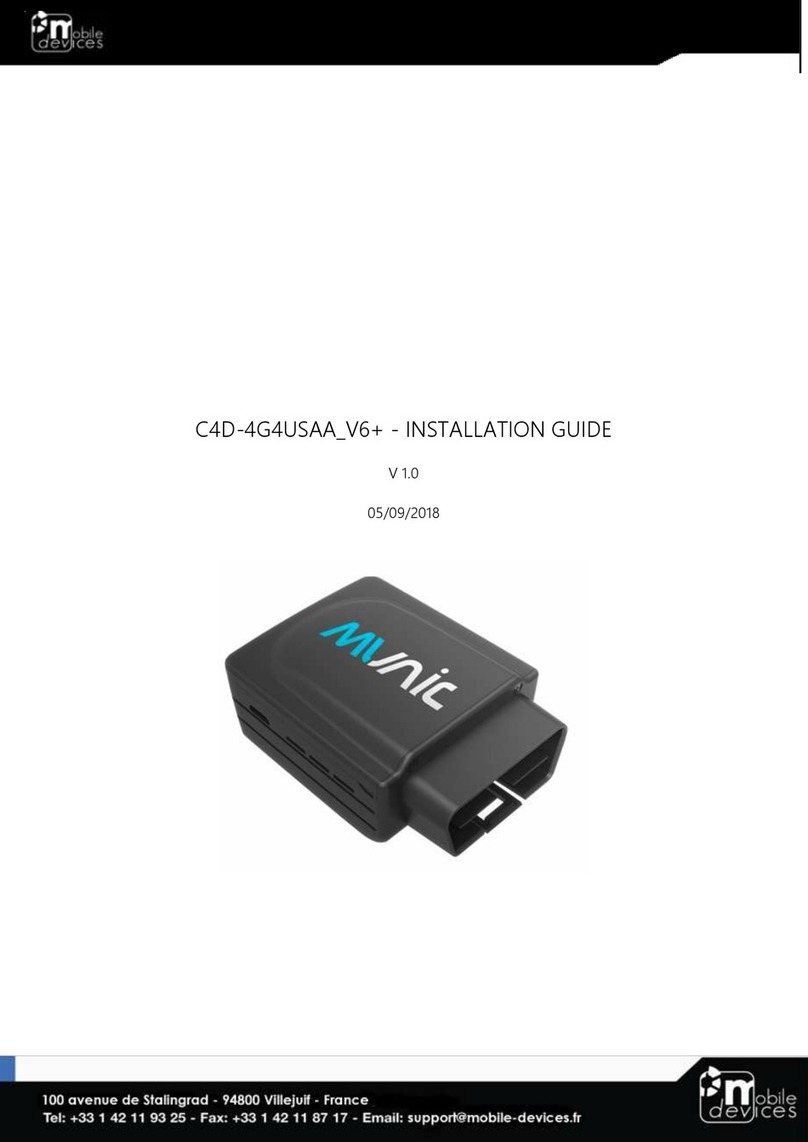
Mobile Devices C4D-2GEUAB V6 User manual

C4D-2GEUAB_V6
INSTALLATION GUIDE
05/10/2019

Table of contents
Preface.....................................................................................................................................3
Warnings and notices ..........................................................................................................3
1. Hardware features ...........................................................................................................4
2. Hardware description......................................................................................................5
2.1. External view...............................................................................................................5
2.2. Internal view................................................................................................................5
2.3. OBD connector pin out ...........................................................................................5
2.4 OBD adapter wires.....................................................................................................6
3. Preparing/installing the device ....................................................................................7
3.1. Open the device to insert a SIM card.................................................................7
3.2. Properly close the device.......................................................................................8
3.3. Install the OBD Dongle ...........................................................................................10
4. LED sequences ................................................................................................................10
5. Support ..............................................................................................................................10

Preface
The information contained in this installation guide is subject to changes in order to improve
the reliability, design or features without prior notice. Mobile Devices Ingénierie reserves the
right to make changes in the content without obligation to notify any person or organisation
of such changes or improvements. Mobile Devices Ingénierie can in no event be held liable
for technical or editorial errors or omissions herein, nor for incidental, special or consequential
damages from the furnishing, performance or use of this installation guide.
Please contact our technical support for current updates and supplemental information
concerning the use and operation of this or other Mobile Devices Ingénierie products.
Warnings and notices
The exclamation point within an equilateral triangle is intended to alert the user
to the presence of important operating and maintenance (servicing)
instructions in the literature accompanying the product.
Please read the installation guidelines, as well as the safety and operating instructions before
operating your device. Follow all instructions and heed all warnings in the installation guide.
There is a risk of explosion if the battery is replaced by a wrong battery type. Please discard
empty battery according to local regulations.
This Device meets the government's requirements for exposure to radio waves. The guidelines
are based on standards that were developed by independent scientific organizations
through periodic and thorough evaluation of scientific studies. The standards include a
substantial safety margin designed to assure the safety of all persons regardless of age or
health.
CE RF Exposure Information and Statement The SAR limit is 2.0 W/kg averaged over one gram
of tissue. The highest SAR value reported under this standard during product certification for
use close to human body is 1.18W/kg. This device was tested for typical body operations at
0.5cm from the body. The use of accessories that do not satisfy these requirements may not
comply with FCC RF exposure requirements, and should be avoided.
Body Operation
This device was tested for typical body support operations. To comply with RF exposure
requirements, a minimum separation distance of 0.5 cm must be maintained between the
user’s body and the device, including the antenna. Third-party belt-clips, holsters, and similar
accessories used by this device should not contain any metallic components. Body
accessories that do not meet these requirements may not comply with RF exposure
requirements and should be avoided. Use only the supplied or an approved antenna.

1. Hardware features
OBD Dongle
Performance
Processor
Atmel SAMA5 - 500MHz
RAM
128 Mbytes
NAND Flash
256 Mbytes
Power supply
External power supply 8-
18V
●
External voltage
measurement
●
Li-pol battery
450mA.h
Communication
Modem
2G QUAD Data module (u-blox
SARA-G450)
GSM antenna
Internal
Positioning
GPS receiver
u-blox UBX-M8030-KT-B3000A
GPS antenna
Internal
Interface & Telematics
features
Micro USB (2.0
Host/Device) (not
powered on internal
battery)
powered (limited to 500 mA on 5V)
when connected to external power
3D Accelerometer
±2g/±4g/±6g/±8g/±16g
LED
A two-coloured LED (controlled by
software)
OBD protocols
CAN, ISO 9141-2, J1850-PWM, J1850-
VPW
Additional CAN interface
Single Wire CAN
Environmental
Connectors
OBD connector
Micro USB
Operating temperature *
-25/+60°C (without battery)
-25/+55°C (with battery)
Dimensions
With OBD connector: 27x60,5x49,5
mm
Without OBD connector: 27x48x49,5
mm"
SIM card
Slot
RF Specification
GSM
GPS(Rx)
GSM900:33dBm
GSM1800:30dBm
* Please read warnings section at the beginning of the installation guide

2. Hardware description
2.1. External view
1. ODB connector
2. microUSB connector
3. LED
2.2. Internal view
4. GSM antenna
5. GPS antenna
6. SIM holder
7. Internal battery*
2.3. OBD connector pin out
Pin #
Comment
1
Single-Wire CAN (optional)
2
J1850+ (PWM/VPW)
3
CAN2 High (optional)
4
Chassis ground
5
Signal ground
6
CAN1 High
7
K line
8
CAN2 Low (Multiplexed
with pin 11) (optional)
10
J1850- (PWM)
11
CAN2 Low (Multiplexed
with pin 8) (optional)
14
CAN1 Low
15
L line
16
Battery voltage
* Please read warnings section at the beginning of the installation guide

2.4. OBD adapter wires
This adapter is only used to connect the OBD to a computer (laptop/desktop).
Pin #
Wire color
2
Yellow
4
Black
5
Grey
6
Green
7
Blue
10
Violet
14
Orange
15
White
16
Red

3. Preparing/installing the device
3.1. Open the device to insert a SIM card

3.2. Properly close the device
First, check that the hole of the electronic card is correctly inserted in the plastic part.
If it’s not inserted proceed as shown below.
Second, insert the GPS antenna as shown below.

Third, check that the micro USB port is correctly inserted on its place.
If it’s not inserted proceed as shown below.
Finally, insert the battery and place the screw.

3.3. Install the OBD Dongle
Connect the OBD Dongle on your vehicle OBD connector.
4. LED sequences
The Dongle has a two-coloured LED, green and red.
When both colours are brightened, you can see an orange light.
Red LED
Green LED
Sequence
Meaning
Sequence
Meaning
OFF
Dongle OFF
ON
Ext. Power/Run
3 times (50ms ON/100ms OFF)
3550ms OFF
No GPRS/No GPS
2 times (50ms ON/100ms OFF)
3700ms OFF
No GPRS/Fix GPS
1 time (50ms ON/100ms OFF)
3850ms OFF
GPRS OK/No GPS
2000ms ON
2000ms OFF
GPRS OK/Fix GPS
30ms ON / 1 s OFF
Shutdown
10ms ON / 2 s OFF
Idle/Sleep and
Shutdown
5. Support
For all questions not related in this installation guide, please contact the support team by
Table of contents
Other Mobile Devices Computer Hardware manuals
Popular Computer Hardware manuals by other brands

Alpha Data
Alpha Data ADM-VPX3-9Z5-RTM user manual

Panasonic
Panasonic 2SB0710A Specification sheet

ADLINK Technology
ADLINK Technology cPCI-3630 Series user manual

Clover Systems
Clover Systems DVX-4 operating manual

Rosewill
Rosewill RFHD-50BK/BL user manual

ekwb
ekwb EK-FB GA AMD KIT INSTALLATION AND MOUNTING MANUAL