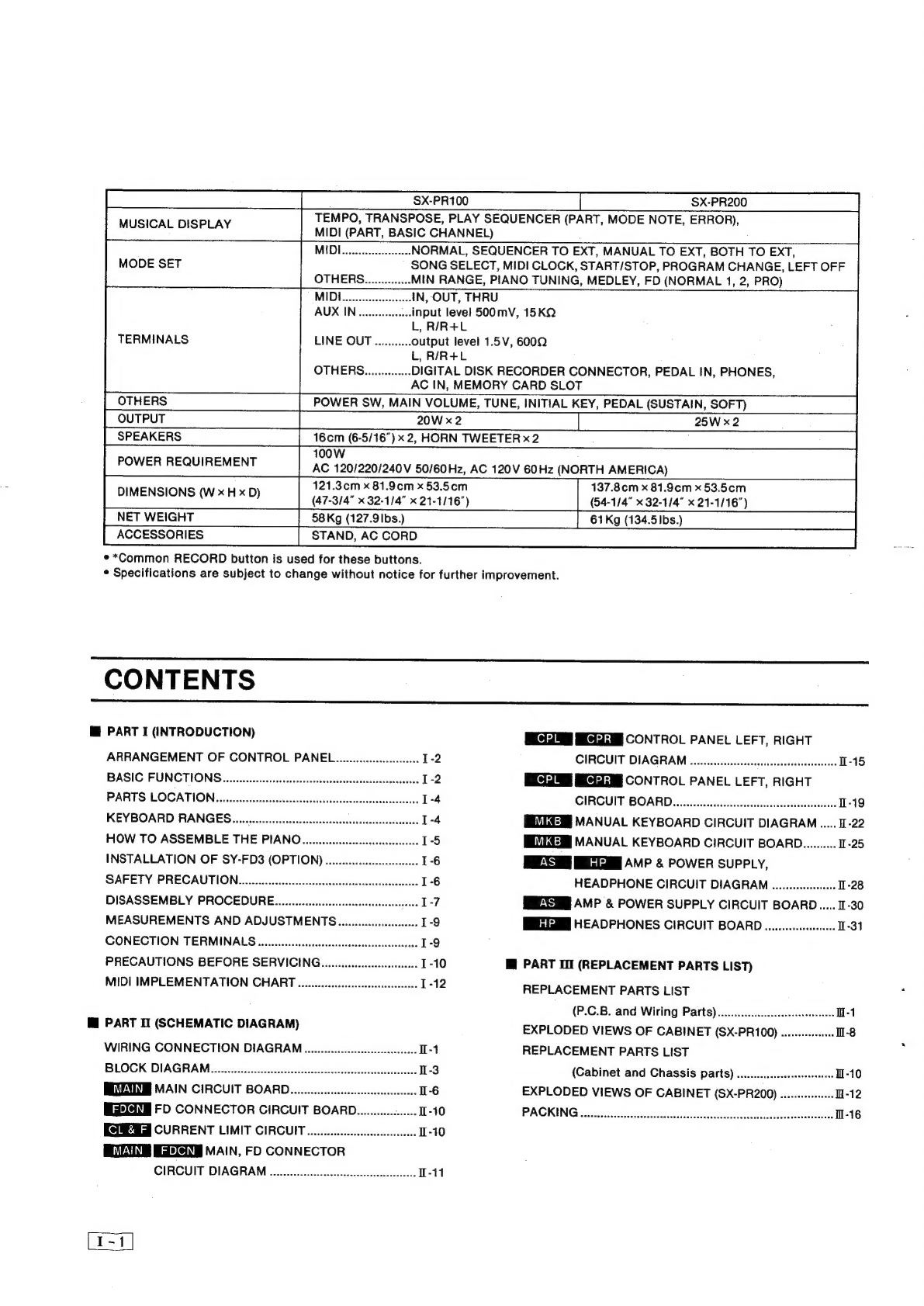
manuals.online logo
Brands
  1. Home
  2. •
  3. Brands
  4. •
  5. Technics
  6. •
  7. Musical Instrument
  8. •
  9. Technics SX-PR100 User manual

Technics SX-PR100 User manual

ORDER
NO.
EMID881229
A4
“Service
Manual
oX-PR100/PR200
(M),
(MC),
(EN),
(El),
(EH),
(EB),
(EF),
(EZ),
(EW),
(EP),
(EK),
(XT), (XL),
(XR),
(XS),
(XD),
(X)
U.S.A.
:
the
United
Kingdom
:
Canada
:
Taiwan
:
Norway,
Sweden,
:
New
Zealand
Denmark,
Finland
:
Australia
Italy
:
Malaysia,
Singapore,
:
Holland
South
Africa
:
Belgium
:
Saudi
Arabia
:
France,
Austria
:
the
Middle
East,
Indonessia,
:
Germany
Hong
Kong,
the
Philippines,
:
Switzerland
Thailand
:
Spain
Photo:
SX-PR200
Specifications
—
SXPRTOO
SXPR200
KEYBOARD
76
KEYS
(16
NOTES
POLYPHONIC)
88
KEYS
(16
NOTES
POLYPHONIC)
KEY
SPLIT
ONGC)
C2
ee
gg
ee
FULLBAND
SETTING
COMPUTER
FSC,
RECORD*
PLAY
SEQUENCER
BASS,
ACCOMP,
LEFT,
RIGHT,
RECORD*
PIANO
1,
2,
E.
PIANO
1,
2,
HARPSICHORD,
GUITAR,
JAZZ
GUITAR,
HARP,
VIBETONE,
PIPE
ORGAN,
JAZZ
ORGAN,
STRING
ENSEMBLE,
BRASS,
TRUMPET,
TENOR
SAX,
RIGHT/ACCOMP
TONE
CLARINET,
FLUTE
OCTAVE
SHIFT
(—2,
—1),
SUSTAIN
PEDAL,
BALANCE
(RIGHT,
ACCOMP)
PIANO
1,
2,
E.
PIANO,
HARPSICHORD,
CLAVI,
GUITAR,
JAZZ
GUITAR,
HARP,
JAZZ
ORGAN,
STRING
ENSEMBLE,
BRASS,
SYNTH
PERC,
ACOUSTIC
BASS,
ELECTRIC
BASS,
CHOPPER
BASS,
SYNTH
BASS
OCTAVE
SHIFT
(+2,
+1),
SUSTAIN
PEDAL
BALANCE
(LEFT,
BASS)
PEDAL
SELECT
SOFT,
SOSTENUTO,
FILL
IN
&
INTRO
.
EFFECT
POW
CRUG
Pee
te
eee
ee
ee
UP
(+C#,
+D,
+D¥,
+E,
+F,
+F#
TRANSPOSE
Souk
be
cnen
a
)
|
KEYBOARD
PERCUSSION
|
35KEYS
ss
C—“*S™COCOCOCOCSCSCté‘C
MARCHICOUNTRY,
WALTZ,
JAZZ
WALTZ,
SWING,
GHA-CHA,
RHUMBA,
TANGO,
SALSA,
RHYTHM
(SELECTORS)
BOSSA
NOVA,
SHUFFLE,
BALLAD,
8
BEAT,
16
BEAT,
DISCO
1,
2,
SWING
ROCK,
FUNK
ROK,
SAMBA
LEFT/BASS
TONE
(CONTROLES)
SYNCHRO
START,
START/STOP,
BALANCE
(DRUMS),
TEMPO,
BEAT
INDICATORS
FILL
IN
&
INTRO
METRONOME
ONE
TOUGH
PLAY
es
ee
ee
ee
Oe
ey
AUTO
PLAY
CHORD
ADVANCED,
BASIC,
BASS
&
ACCOMP
1,
2,
3,
4
PROGRAM
CHORD
PCC,
RECORD*,
CHORD
COMPOSER
(KEYBOARD)
'§-,
<
COMPUTER
DS,
—H,
Gyr
Matsushita
Electric
industrial
Co.,
Ltd.
Panasonic
Hawaii,
inc.
Panasonic
Sales
Company,
oe
Central
P.O.
Box
288,
Osaka
530-91,
Japan
99-859
Iwaiwa
Street
Division
of
Matsushita
Electric
ec
nics
P.O.
Box
774
of
Puerto
Rico,
Inc.
Matsushita
Services
Company
Honolulu,
Hawaii
96808-0774
Ave.
65
De
Infanteria,
KM
9,7
50
Meadowland
Parkway,
Victoria
Industrial
Park
Secaucus,
New
Jersey
07094
Carolina,
Puerto
Rico
00630
3S56
SX-PR100
SX-PR200
eee
TEMPO,
TRANSPOSE,
PLAY
SEQUENCER
(PART,
MODE
NOTE,
ERROR),
MIDI...
eseeeseeees
NORMAL,
SEQUENCER
TO
EXT,
MANUAL
TO
EXT,
BOTH
TO
EXT,
MODE
SET
SONG
SELECT,
MIDI
CLOCK,
START/STOP,
PROGRAM
CHANGE,
LEFT
OFF
re
MIN
RANGE,
PIANO
TUNING,
MEDLEY,
FD
(NORMAL
1,
2,
PRO)
MIDI...
eee
IN,
OUT,
THRU
AUX
IN
uu...
input
level
500mV,
15KQ
L,
R/R+L
TERMINALS
LINE
OUT
...........
output
level
1.5V,
600Q
L,
R/R4+L
OTHERG...........00
DIGITAL
DISK
RECORDER
CONNECTOR,
PEDAL
IN,
PHONES,
AC
IN,
MEMORY
CARD
SLOT
OTHERS
POWER
SW,
MAIN
VOLUME,
TUNE,
INITIAL
KEY,
PEDAL
(SUSTAIN,
SOFT)
OUTPUT
20W
x2
25W
x2
SPEAKERS
16cm
(6-5/16")
x
2,
HORN
TWEETER
x2
100W
POWER
REQUIREMENT
AG
120/220/240V
50/60Hz,
AC
120V
60Hz
(NORTH
AMERICA)
121.30m
x
81.9¢m
x
53.5cm
137.8cm
x
81.9¢6m
x
53.5cm
DIMENSIONS
(Wh)
(47-3/4"
x
32-114"
x
21-1116")
54-114"
x
32-1/4"
x21-1/16")
NET
WEIGHT
58Kg
(127.9|bs.)
61Kg
(134.5lbs.)
ACCESSORIES
STAND,
AC
CORD
**Common
RECORD
button
is
used
for
these
buttons.
*
Specifications
are
subject
to
change
without
notice
for
further
improvement.
CONTENTS
@
PART
I
(INTRODUCTION)
CONTROL
PANEL
LEFT,
RIGHT
ARRANGEMENT
OF
CONTROL
PANEL........csssssssscseeeees
12
CIRCUIT
DIAGRAM
.....ccsssesssssescssssssecesesesessssessees
1-15
BASIC
FUNCTIONS
.....ccccccccsssssssssssssssasssssssessecseceeseeseeeeneees
CONTROL
PANEL
LEFT,
RIGHT
PARTS
LOCATIONS
yiccni
iin
tkaceasiieneattea
cathe:
.
GIRCUIT
BOARD
i)
sisiiieiiosciscasttectsalcadatinacae
1-19
KEYBOARD
RANGES......
MEVIGEMI
MANUAL
KEYBOARD
CIRCUIT
DIAGRAM
.....
1-22
HOW
TO
ASSEMBLE
THE
PIANO.....ssssssssscsssssscssscceseesee
1-5
MANUAL
KEYBOARD
CIRCUIT
BOARD..........
1-25
INSTALLATION
OF
SY-FD3
(OPTION)
....ccssccssssssssssssseeees
1-6
SS
BE
AMP
&
POWER
SUPPLY,
SAFETY
PRECAUTION...csssssssssssssssssssssssscsssssescensnsssessssesess
1-6
HEADPHONE
CIRCUIT
DIAGRAM
......ssssssssssee
1-28
DISASSEMBLY
PROCEDURE......s.cssccssessssscssesssssscsesessenne
Le
MREXSH
AMP
&
POWER
SUPPLY
CIRCUIT
BOARD...
1-30
MEASUREMENTS
AND
ADJUSTMENTS
ct
HEADPHONES
CIRCUIT
BOARD
......scsssssessseees
1-31
CONECTION
TERMINALS
.occccsecscccccscsscccssseesssensssessssseseeee
1-9
PRECAUTIONS
BEFORE
SERVICING.
........cccsscccsssssssseee
1-10
M@
PART
II
(REPLACEMENT
PARTS
LIST)
MIDI
IMPLEMENTATION
CHART
oencccccccscscccsccceccececesecene
I-12
REPLACEMENT
PARTS
LIST
(P.C.B.
and
Wiring
Parts)
..........cccccsessseeseresees
H-1
Mi
PART
TI
(SCHEMATIC
DIAGRAM)
EXPLODED
VIEWS
OF
CABINET
(SX-PR100)
......--..00000
1-8
WIRING
CONNECTION
DIAGRAM
ooscseccsccscccscsscccccneceeeee
I-1
REPLACEMENT
PARTS
LIST
BLOCK
DIAGRAM
(Cabinet
and
Chassis
parts)
..............0
MAIN
CIRCUIT
BOARD.............cccccsccsesseesssseeees
1-6
EXPLODED
VIEWS
OF
CABINET
(SX-PR200)
FD
CONNECTOR
CIRCUIT
BOARD............
s+
0-10
PACKING
%
sci.
doco
cetasSha
tila
shcdisscdoatiad
ass
assctectacsban
deluasssvindts
CURRENT
LIMIT
CIRCUIT
MAIN,
FD
CONNECTOR
CIRCUIT
DIAGRAM
......
es
csceeceseessesesssesteeetsenee
I-11
ad
ARRANGEMENT
OF
CONTROL
PANEL
4
MEMORY
CARG
|
ml
[
|
|
|
@
|
8
|
@
®
||
|
3] 4)
@
5
@
|
|
ll
||
i
|
|
i
7 s
!
|
i
eoerh
CAN
ij
seis
|
$
oye
TONE
Pi
TRANSPOSE
PEDAL
(pg
ER
er
fe
ut
PEAY
pce]
|—
RHYTHM.
|
LEFT
vaass
TOME
RIGHT
accor
ae
LAY.
BOWER
i
cles
ia
oer
TeANE
ey
|
basal
a
|
[CHA-CHA)RMUMBA)
TANGO
|
SALSA
[enssAWDA|
oO
—~
Ek
MUSICAL
DispLAY
|
OCT
SHIFT
Der
Sule
SEQUENCER
|
|
|
|
|
T
Teo
ocd
rp
ee
=|
(eemey
ce
“Goa
clavicuitan
GUNAR
Hane
9
92
ieee
jE
PANS)
"Elona
cuitaa
sUNAR
WARP
viBeTONE
ent
:
eown
e
S
ACCOMP.
DRUMS.
LEFT.
RIGHT
ADVANCED:
BAS!
sie
BALL
EAT
|
CISCO
1]
BISCO
2
/swING
ROCKIFUNK
ROCK}
SAMBA
|
«Ee]
=)
1
2
PIANO
CI
LAN
AW
a
GUI
VIBETON
LEFT
RIGHT
a
}
ie
e
i
oS
Ae
NS
we
ja
‘QVANCED.
BASIC.
SHUFFLE]
BALLAD!
8.8€aT
|
16
SEAT.|
tsco
1!
o1SCO
2
swine
RocKlEUNK
ROCK!
SAMBA
Os
if
|
red
a)
7
4
g
3 S
6 O S
3
By
6
6
6
S
6 e
3
"a
&
Ooi
C
oe?
|
>
randy
ooo
im
|
©
o
6
ra}
ry
ry
ry ry r)
iy
1|
|
ol
F
Cy
ROO”
O-
= E
=
ae
s
—
ey
]
ie
{
{ ]
OFF
om
ON
Pa
3
ona
i
bel
eects
Cree
J
bo
cE
ca
Teed
ee
saan
|
\
a
pe
[
{
S|
©
SOSTENY
=
|
|
ASS
ceOMP—
{
oF
Shay
Marx
bees
JA,
STRING
SYNTH:
=
BASS
‘SUSTAIN
KEY.
PIPE
JAZZ
STRING
TEN
SUSTAIN
KEYBOARG
1
MAIN
VOLUME
boa
cual
afl
jal
afojaloyay
nase
a
|
ENOING
START"
START/STOP
FILL
IW
&
INTRO
ONE
TOUCH
PLAY
METRONOME
0.0
0
OBEAT
|
ORGAN
‘agouste
BRASS
PERC
ACOUSTIC.
ELECTRIC
CHOPPER
SYNTH
PEDAL
SPLIT
ORGAN ORGAN
ensemaie
BRASS
TRUMPET
SAX.
CLARINET
FLUTE
“PEDAL
PERCUSSION
|
CHORUS
BASS
ACCOM
MOV
cccsveaanatt
ueHe
MAX
I
° ° 3 ° °
°
° °
LOW
TEMPO
FAST
|
8 ° °
° °
° ° ° ° °
°
° ° ° ° ° °
° ° 3 °
i
pias
;
—
Bn
==
(oy
Thal
Ed
ES
Eases
{
]
}
|
]
Ez
J
Beh
t
(=o
|
Lod
Eo)
fe]
Ee]
{
[
(e]
let
{
ea)
a
ara
esc
uannaarenerearc
omer
onecress
MIN
PIAND.
‘MEDLEY
NORMAL)
NORMAL?
PRO’
(wane
SE)
ia
TUNING
REREAD
UREN
RETR
ae
Be
[eae
a
°
° 2
|
v
'
INITIAL
yr
Hl
re
8
as
,
&
;
ss
Eee
5
>
4
CHORO
COMPOSER
QQ,
6
ge
Sg
Soe
S&
eS
42
8
or
8h
ge
Bw
Fok
ggr
Ly
A
nme
Ff
ae
8e
=
PS
_
Se
|
BASIC
FUNCTION
@
MUSICAL
DISPLAY
Display
shows
tempo
speed
and
remaining
strage
notes
capacity
which
can
be
stored
in
the
play
sequencer.
@
RIGHT/ACCOMP
TONE
This
section
is
used
to
set
the
voice
and
effects
for
the
right
part
of
a
split
keyboard.
Choose
from
717
voices
on
the
PR100/PR200.
Available
effects
are
sustain,
octave
shift
and
chorus.
©
LEFT/BASS
TONE
Select
a
voice
and
effects
for
the
left
part
of
a
split
keyboard,
or
for
the
whole
keyboard
when
the
split
function
is
not
used.
There
are
16
voices
for
the
PR100/PR200.
The
sustain
and
octave
shift
are
available
for
the
left
keyboard
also.
©
Split
function
The
keyboard
can
be
split
into
left
and
right
parts
for
which
different
voices
and
effects
can
be
assigned.
The
split
location
can
be
set
at
G2,
C3
or
C4.
©
CHORUS
A
CHORUS
effect
can
be
applied
to
give
the
sound
greater
depth.
—
SOFT
SUSTAIN
|
|
|
ed
@
TRANSPOSE
Raise
or
lower
the
key
of
the
entire
piano
with
the
UP
and
DOWN
buttons.
The
transposed
key
is
shown
on
the
MUSICAL
DISPLAY.
@
KEYBOARD
PERCUSSION
Turning
this
button
on
transforms
your
keyboard
into
a
whole
band
of
percussive
instruments
and
special
sounds.
The
keys
are
picture-coded
for
quick
and
easy
selection.
@
BALANCE
The
volumes
for
the
RIGHT,
LEFT,
DRUMS,
ACCOMP
and
BASS
parts
are
adjusted
with
their
respective
A
and
VW
buttons.
No
sound
is
produced
if
both
indicators
are
off.
©
RHYTHM
Select
a
preset
rhythm
from
the
9
x
2
matrix
and
start
it
instantly
with
the
START/STOP
button.
BEAT
in-
dicators,
SYNCHRO
START,
METRONOME,
TEMPO
adjust
and
volume
control
(DRUMS)
make
playing
easy.
And
regular
Technics
features
such
as
automatic
FILL
IN
&
INTRO,
ENDING
pattern
and
ONE
TOUCH
PLAY
add
spice
to
your
performance.
ie
[1-2]
|
jes
AUTO
PLAY
CHORD
@
®
®
This
feature
is
selected
when
the
ADVANCED
or
BASIC
button
is
turned
on.
The
bass
and
accom-
paniment
are
automatically
produced
when
you
play
a
key
on
the
left
part
of
the
keyboard.
Four
BASS
&
ACCOMP
buttons
provide
a
variety
of
rhythmic
and
melodic
patterns
matched
to
the
selected
rhythm.
PROGRAM
CHORD
COMPUTER
Store
the
chord
accompaniment,
rhythm
sequences,
fillins,
etc.
of
an
entire
song
in
the
piano,
then
have
it
played
back
automatically
while
you
play
the
melody.
With
the
keys
at
the
right
end
of
the
keyboard,
store
whole,
half-or
quarter-measure
chords,
specify
repeat
play,
and
more.
PLAY
SEQUENCER
With
this
feature
you
can
separately
play
and
store
the
right,
left,
accompaniment
and
bass
parts
for
an
entire
tune.
Then
have
the
whole
synchronized
sequence
played
back
automatically.
:
PEDALS
Control
the
sustain
and
quality
of
piano
tones
with
the
sustain
pedal
and
soft
pedal.
Or
you
can
choose
to
activate
the
automatic
rhythm
or
fill-in
with
the
soft
pedal
by
using
the
PEDAL
SELECT
button.
[1-3
®
Digital
Disk
Recorder
*SY-FD3
(Option)
|
ed
@
SUSTAIN
PEDAL
On
the
PR100/PR200,
the
sustain
pedal
is
a
four-
stage
pedal,
and
the
length
of
the
sustain
is
controlled
by
the
degree
to
which
the
pedal
is
depressed.
@
SOFT
PEDAL
The
soft
pedal
can
also
be
used
as
a
SOSTENUTO
pedal.
@®
MEMORY
CARD
Record
your
performances
or
just
the
registrations
on
optional
memory
cards.
Recall
and
reset
the
piano
registrations—or
have
a
whole
tune
performed
automatically—in
just
seconds!
@
DIGITAL
DISK
RECORDER
SY-FD3
(option)
The
Digital
Disk
Recorder
allows
virtual
unlimited
storage
and
playback
of
your
piano
performances.
A
long
tune,
or
up
to
ten
shorter
tunes,
can
be
stored
on
each
digital
memory
disk.
_PARTS
LOCATION
Amp_&
Power
Supply
P.C.B.
|
AS
—
ia
Control
Panel
Left
P.C.B.
Power
Transformer
——
WAV
Nie
Main
P.C.B.
Power
Switch
Conirol
Panei
Right
P.C.B.
Horn
Tweeter,
SP4
Horn
Tweeter,
Speaker
j
.
'
46cm
80
—
oe
Me
Seeaker
(Inside)
ue
HP
Headphone
P.C.B.
(Inside)
|
[Photo-1]
KEYBOARD
RANGES
C¥41
Fas
Atso;
D#55
Gteo
‘Ces
F#70
At
7s
{
{ 1
i
i i
i
1
'
'
1
u
i
T
1
'
t
yl
1
ed
1
i
Pay
:
‘
ee
Cae
1
'
i
i
iC#5;
F*io'A®ia)
;D#19
iG#2a,
iC#2o!
F
#34
1A®38!
|
D843
|G#ag!
(C%53'
F*%58!A*%621
'D%67
'G%72!
iC#77'
F%82
|A*es
8va
ze
Popes
ae
|
©
ie
q
SpE
a
:
aaa
a?
a
7
~
a
Ss
4
t
i '
4
7
Middle
C
‘
‘
}
i]
'
i
|
}
i]
'
' i
!
|
t
‘
H
i
1
o
=
u
n
a
e
a
Sel
as
eomeree
area
e
coms
=
H
a
=
=
—
2
eo
! ' :
a
'
i
!
1
;
1 '
Ld
i
C
4 1 i
i
‘
8
va
bassa
:
i
i
:
4
/
i
j
i
'
i
i
1 t
j
'
\
|
5;
i
i
i
'
i
\
|
i
;
:
! i
i
\A®2,
D#7.
G#i2
iC#i7
F#22
A*26!
D#31
G#as
!
i
i
D879
Gag
|
‘
'
t
1
1
1
:
t
1
1
1
:
i
'
t
'
‘
f~
At}
Ca!
Es
}Gi1
Bis
|
Dig!
Fat
|
A2s
|
Cae
|
Es2
1G36
|
Bag
|
Da2|
Fas
|
Aaa!
C52
'Ese
|
Gso
|
Bes
|
Des
|
Fea
|
A731
C76
|
Eso
|
Ges
|
Bar
|
Bs
De
Fo
Ais
Cie
E20
G23
B27
Dso
Fas
A37
Cao
Ess
G47
B51
Dsa
F57
Aci
Ces
Ess
G71
B75
D738
Fe:
Aas
Cas
is
for
PR200
only
[1]
Attach
the
side
panels
to
the
pedal
box
using
the
for
black
bolts.
Set
the
piano
unit
on
the
stand,
and
secure
it
to
the
stand
with
the
four
brown
bolts.
Side
panel
i
i
|
|
Side
panel
[Fig.
3]
Place
the
stand
upright,
and
fit
the
crossboard
onto
the
L
brackets
from
above.
Secure
it
with
the
four
black
bolts,
and
cover
the
bolt
heads
with
the
caps.
Sensaraits
by
Maco
sated
in
Bee
le
\
gs
|
|
|
|
|
|
if
INSTALLATION
OF
SY-FD3
(OPTION)
¢
Make
sure
that
the
power
to
the
Technics
piano
is
turned
off.
¢Remove
the
cover
from
the
connector
unit.
¢Completely
insert
the
right
and
left
guide
rails
into
the
grooves
of
the
connector
unit.
¢
Affix
the
guide
rails
to
the
underside
of
the
piano
with
the
four
bolts
®.
Insert
the
Digital
Disk
Recorder
(SY-FD3)
along
the
guide
rails,
and
push
it
in
firmly
and
completely.
*
Secure
the
Digital
Disk
Recorder
to
the
left
guide
rail
with
screw
©.
SA
F
ETY
P
R
EC
AUTIO
N
(This
“safety
precaution”
is
applied
only
in
U.S.A.)
¢
Safety
Precaution
.
Before
servicing,
unplug
the
power
cord
to
prevent
an
electric
shock.
.
When
replacing
parts,
use
only
manufacturer’s
recommended
components
for
safety.
.
Check
the
condition
of
the
power
cord.
Replace
if
wear
or
damage
is
evident.
:
.
After
servicing,
be
sure
to
restore
the
lead
dress,
insulation
barriers,
insulation
papers,
shields,
etc.
.
Before
returning
the
serviced
equipment
to
the
customer,.
be
sure
to
make’
the
following
insulation.
resistance
test
to
prevent
the
customer
from
being
exposed
to
a
shock
hazard.
OAbhohd
=
*
Insulation
Resistance
Test
;
1.
Unpulg
the
power
cord
and
short
the
two
prongs
of
the
plug
witha
jumper
wire.
2.
Turn
on
the
power
switch.
3.
Measure
the
resistance
value
with
ohmmeter
between
the
jumpered
AC
plug
and
each
exposed
metal
cabinet
part,
such
as
screw
heads,
connectors,
contro!
shafts,
handle
brackets,
etc..
cae
Mesurements
should
range
from
4MQ
to
infinity
to
all
exposed
nai
parts.
Ohmmeter
Resistance=4MQ
to
DISASSEMBLY
PROCEDURE
[1]
How
to
remove
the
keyboard
cover
©
Left
shaft
slide
to
inside
with
tool
as
shown
;
Fig.
8-©.
@®
Lift
upward
left
side
of
keyboard
cover
as
shown
as
Fig.
8-@.
®
Remove
the
keyboard
cover
slide
it
leftword
as
shown
Fig.
8-@.
‘
[2]
How.to
remove
the
top
cover
*Remove
the
keyboard
cover
according
to
procedure.1.
:
@
Remove
the
2
Screws
®
and
2
screws
©
which
fasten
the
top
cover
located
under
‘the
shelf
board.
@
The
top
cover
can
be
opend
by
lifting.
r=
mM
HN
Ae
[3]
How
to
remove
the
keyboard
-©Open
the
top
cover
according
to
procedure
2.
‘@
Remove
the
8
screws
@
which:
fasten
the
keyboard.
mmm
NS
[Fig.
10]
1-7
[4]
How
to
remove
the
keys
Remove
the
keyboard
according
to
procedure
3.
©
Lift
up
the
claw
as
shown
Fig.
11-©
@
The
key
push
to
forward
as
shown
Fig.
11-@.
Key
can
be
removed
from
chassis.
®
Lift
up
the
key
and
take
it
out
from
chassis.
Note:
«In
the
case
of
disassembly
black
key
remove
the
right
and
left
white
key
at
first
and
after
that
black
key
can
be
removed.
Reassembly
method
©®
Insert
the
spring
in
to
the
hammer
notch
with
the
tang
pointings-up
as
shown
in
Fig.
11-©.
:
@
While
holding
the.
spring
against
the
hammer,
[Fig.
11]
place
the
rear
edge
of
the
spring
in
the
notch
in-
side
the
rear
edge
of
the
key.
®
Slowly
push
the
key
down
into
the
slots
in
the
chassis.
.
[5]
How
to
remove
the
printed
circuit
boards
FD
Connector
P.C.B.
(Fig.
12)
Remove
the
3
screws
©
on
the
connector
unit.
Main
P.C.B.
¢Remove
the
6
screws
@
on
the
Main
P.C.B.
(Fig.
13)
¢Remove
the
3
screws
@
on
the
back
of
the
top
cover.
(Fig.
14)
*In
the
case
of
remove
the
P.C.B.
except
the
above-mentioned,
release
the
clows
of
P.C.B.
holder
and
remove
the
screws
on
the
each
P.C.B.
[Fig.
12]
P.C.B.
asm
P.C.B.
CPL
OOOO
OO
©©
6
[al
[Fig.
14]
[Fig.
13]
MEASUREMENTS
AND
ADJUSTMENTS
@
Measuring
Equipment
©
Oscilloscope
20MHz,
10:1
probe
¢
Oscillator,
1kHz
sine
wave,
O~10Vp-p,
600
¢
Capacitor,
50V
1F
(ECEA1HNO10S)
ADJUSTMENT
ADJ.
CONNECT
METER
ADJUSTMENT
MEASURING
CONDITIONS
EQUIPMENT
POINT
METER
TO
READING
BBD
bias
any
position
Oscilloscope
P.C.B.
VR2
|
1c53-@
Photo-A
(CHORUS)
and
oscillator
.
Connect
the
oscilloscope
to
IC53-@
pin
of
circuit
board.
.
Input
1kHz
sine
wave
to
IC52-@
pin
by
oscillator
through
capacitor
of
less
than
50V
1pF.
Then,
adjust
the
output
level
of
oscillator
until
the
sinewave
on
the
oscilloscope
is
clipped.
.
Adjust
VR2
so
that
the
output
waveforms
on
the
oscilloscope
are
evenly
clipped
at
top
and
bottom.
O22
vwWOV.
OS
assdiv
‘O.2
WOW
OS
espiv
-
[Photo-A]
~~
[Photo-B]
CONNECTION
TERMINALS
(On
the
rear
panel)
TUNE
MDE
PEDAL
IN
AUXIN,
LINE
OUT
ca
ihe
pull
nN
Boo
0
Boo
OU
3)
00
00
MTUNE
i
MID!
(Musical
Instrument
Digital
Interface)
During
an
ensemble
performance
with
other
MIDI
is
standard
specification
that
enables
connec-
instruments,
fine
adjustments
of
pitch
can
be
made
tion
to
equipment
such
as
synthesizers
and
personal
using
this
knob.
computers.
Data
transmission
and
reception
are
possible
between
the
Technics
Digital
Piano
M@
PEDAL
IN
instruments
provided
with
MIDI
terminals.
Connect
the
cord
from
the
included
stand
to
this
;
oe
at
terminal.
IN:
The
terminal
that
receivers
data
from
exter-
nal
equipment.
Wi
AUX
IN
(input
level
500
mv,
15KQ)
OUT:
The
terminal
that
transmits
data
from
the
piano
to
external
equipment.
The
terminal
that
transfers
data
from
the
IN
terminal
directly
to
other
equipment.
Other
instruments
such
as
a
rhythm
machine
or
THRU:
sound
module
can
be
connected
to
the
piano
so
that
.
the
sound
is
output
from
the
piano.
To
receive
monaural
sound,
connect
instruments
to
the
R/R+L
terminal.
¢
Use
a
5-pin
DIN
cord
flese
than
15m
long)
for
these
connections.
ME
LINE
OUT
(output
level
1.5V
6009)
By
plugging
into
a
Technics
Tone
Cabinet
or
a
high-
power
amplifier,
the
sound
can
be
reproduced
at
high
volume.
(Use
the
R/R+L
terminal
when
output-
ting
monaural
sound.)
(13)
PRECAUTIONS
BEFORE
SERVICING
@
Precautions
for
measuring
of
the
output
waveforms.
1.
Please
set
the
INITIAL
mode
before
measurement.
e
INITIAL
mode:
Press
the
FSC
button
to
turn
it
on,
and
then
press
the
INITIAL
key
on
the
keyboard.
2.
After
INITIAL
mode,
set
the
measurement
conditions
as
each
check
points.
3.
The
waveform
was
measured
by
‘National
Digital
Storage
Oscilloscope
VP-5730A”.
Therefore
the
waveforms
of
musical
tone
signals
shown
may
somewhat
change
due
to
variation
of
timing
of
measure.
4.
The
voltage
shown
in
the
photo
is
1/10
of
the
actual
value.
However,
the
actual
voltage
is
10
times
of
as
shown
in
this
photo.
5.
The
tone
signal
output
varies
with
the
level
of
key
pressing
force.
In
this
measurement,
the
waveform
obtained
with
maximum
key
pressing
force
is
shown.
However,
the
output
level
and
waveform
may
very,
depending
on
the
timing
and
measuring
instrument
and
other
conditions
in
the
measurement.
important
safety
notice:
Components
identified
by
/\
mark
have
special
characteristics
important
for
safety.
When
replacing
any
of
these
components,
use
only
manufacturer’s
specified
parts.
@
Symbolic
Marks
The
symbolic
marks
for
resistors
and
capacitors,
which
are
used
in
the
circuits
for
this
Piano,
are
as
shown
in
TABLE-1
and
TABLE-2.
1.
RESISTORS
¢Resistors
without
symbolic
mark
are
FIXED
CARBON
FILM
RESISTORS
(ERD-type).
All
resistors
are
1/4WATT,
+5%
TOLERANCE
unless
otherwise
designated
in
the
schematic
diagrams.
(TABLE-1)
SYMBOL
SPECIFICATION
SYMBOL
SPECIFICATION
®
Fixed
Carbon
Film
Resistors
®
Fixed
Metal
Film
Resistors
|
“FLAME-PROOF”
(ERD—F—type)
“FLAME-PROOF”
(ERX—type)
Fixed
Wire
Wound
Resistors
Fuse
Type
Fixed
Metal
Oxide
Film
“FLAME-PROOF”
(ERF—type)
Resistors
“FLAME-PROOF”
Fixed
Metal
Oxide
Film
Resistors
Fuse
Type
Fixed
Carbon
Film
Resistors
“FLAME-PROOF”
(ERG—type)
“FLAME-PROOF”
(ERD2FC—type)
(ERQ—type)
aa
Fixed
Metal
Film
Resistors
(Precision
and
High
Stability)
(ERO—type)
@
)
2.
CAPACITORS
¢
Capacitors
without
symbolic
mark
are
POLYESTER
CAPACITORS.
(ECQM-type,
ECQG-type,
+
10%
Tolerance)
©
Polarized
capacitors
without
symbolic
mark
are
Aluminum
Electrolytic
Capacitors.
(ECEA—type,
+20%
Tolerance)
(TABLE-2)
SYMBOL
SPECIFICATION
TYPE
|
@
-
|
Non-Polarised
Electrolytic
Capacitors
ECEA—N—type
2
Oo
Non-Polarised
Electrolytic
(for
Network
System)
ECEA—Y—type
|
®
|
Aluminum
Electrolytic
Capacitors
(Miniature
type)
ah
opal
ae
te
S)
Aluminum
Electrolytic
Capacitors
(Low
leakage
current
type)
ECEA—M—type
|
oO
|
Temprature
Compensating
Ceramic
Capacitors
ECC—type
>.
1
High-Dielectric
Constant
Ceramic
Capacitors
ECK—type
aaa
Metalized
Polyester
Film
Capacitors
for
Across
the
Line
ECQ—EW—type
are
Aluminum
Electrolytic
Capacitors
for
smooting
Circuit
ECES—type
i
Symptoms
which
appear
to
be
signs
of
trouble
The
following
changes
in
performance
may
occur
in
the
Technics
digital
piano
but
do
not
indicate
trouble.
Phenomenon
When
many
keys
are
pressed
at
the
same
time,
not
all
of
them
sound.
When
the
AUTO
PLAY
CHORD
is
off,
the
maximum
number
of
notes
wheich
can
sound
simultaneously
from
the
combined
right
and
left
keyboards
is
12.
When
the
AUTO
PLAY
CHORD
is
on,
the
maximum
is
8
notes.
Sustain
does
not
work,
even
when
the
|
Sustain
is
set
separately
for
the
right
and
left
sections.
Turn
the
sustain
pedal
is
pressed.
SUSTAIN
PEDAL
button
on
for
either
or
both
parts.
¢When
a
PLAY
SEQUENCER
button
is
on
and
a
song
without
any
rhythm
is
stored,
the
rhythm
does
not
start.
¢When
the
clock
mode
is
set
to
MIDI
CLOCK,
the
rhythm
does
not
start
if
no
MIDI
clock
signal
is
received
from
another
instrument.
When
using
only
the
piano,
return
the
clock
mode
to
the
internal
clock,
for
example
by
turning
off
the
POWER
once.
The
rhythm
does
not
start.
Selections
must
be
made
within
5
seconds
after
the
RECORD
button
is
pressed.
After
5
seconds
the
RECORD
button
turns
off
and
no
further
storage
is
possible.
? ‘
Nothing
is
stored
in
the
PROGRAM
CHORD
COMPUTER
or
PLAY
SEQUENCER.
Nothing
is
‘stored
in
the
PROGRAM
CHORD
COMPUTER.
When
storing
chords,
press
a
measure
key(
FA,
FH,
BH
)
while
holding
down
the
chord.
Be
sure
that
the
chord
is
not
released
—
until
after.
the
measure
key
is
pressed.
a
When
the
AUTO
PLAY
CHORD
is
off,
the
BASS
and
ACCOMP
do
not
sound;
only
the
rhythm
changes.are
performed.
To
play
back
the
accompaniment,
select
an
AUTO
PLAY
CHORD
mode
(BASIC
or
ADVANCED).
When
playing
back
the
PROGRAM
CHORD
COMPUTER,
the
accompani-
ment
is
not
performed.
ie
¢
Storage
is
not
possible
when
the
Fsc
button
is
on.
Turn
it
off
before
storing.
elf
another
PLAY
SEQUENCER
indicator
is
lit,
press
the
START/STOP
button
for
automatic
performance
of
the
stored
part.
Another
part
can
then
be
stored.
The
RECORD
and
PLAY
SEQUENCER
indicators
are
flashing
slowly,
but
storage
is
not
performed.
When
playing
back
the
PLAY
SEQUENCER,
a
fast
rhythm
tempo
becomes
slower.
This
may
happen
when
an
extremely
large
number
of
notes
are
programmed
to.be
played
at
one
time..
Slow
down
the
tempo,
or
decrease
the
number
of
notes
to
be
played
at
one
time.
When
performing
the
playback
operation
from
a
memory
card,
the
piano’s
internal
memory
changes
to
that
stored
in
the
memory
card.
To
preserve
a
song
in
the
piano’s
memory,
store
it
in
a
memory
card.
When
the
operation
to
play
back
from
the
optional
memory
card
is
performed,
the
contents
of
the
piano’s
internal
memory
are
erased.
The
normal
sound
is
not
produced
when
the
keys
are
played.
Instead,
the
sounds
from
rhythm
instruments
are
heard.
When
the
KEYBOARD
PERCUSSION
button
in
the
RIGHT
TONE
block
is
on,
the
sounds
of
the
percussive
instruments
indicated
above
the
keys
are
produced.
To
return
to
the
normal
piano
sound,
select
a
different
tone
in
the
RIGHT
TONE
block.
,
¢Press
the
FSC
(FULLBAND
SETTING
COMPUTER)
button
to
turn
it
on,
and
then
press
the
INITIAL
key
on
the
keyboard.
lf
the
buttons
and
keys
do
not
return
to
normal,
turn
off
the
POWER
once,
then
on
again.
Turn.on
the
FSC
button
and
press
the
INITIAL
key.
:
No
sound
is
produced
when
the
keys
No
sound
is
produced
with
the
LEFT
and
RIGHT
indicators
in
the
are
pressed.
BALANCE
section
are
off.
.
Press
the
A
buttons.
The
keys
on
the
left
keyboard
do
not
When
on
TONE
indicator
is
lit
for
the
left
section,
the
left
keyboard
keys
sound.
do
not
sound.
Select
and
press
a
TONE
button
for
the
left
keyboard.
The
buttons,
keys,
etc.
malfunction.
e
Auto
Play
Chord.................Basic
e:
Rhythm
cee
ses
ae
©
Right
TOMG
vec
eeccccceeceesseeeees
i
°
Bass
&
Accomp
a)
*
Balance
(all)
...............
tee
°
Balance
(Right)
a
©
StartlStop
ccscesesssecccseessnssssens
art
*
Ckey...ON
°
Tempo...
J
©
Keyboard
0c
ccsccucicc:
@
Drums
@©
Accomp
nite
ee
GT
[
ie
Bee
=
}
®
APC...Basic
¢
Rhythm...Salsa
e
APC...Basic
*
Rhythm...Disco
I
eSPAythM
ee
eos
March
®
Bass
&
Accomp...3
°
Tempo...
|
=50
*
Bass
&
Accomp...2
*
Tempo...
|
=120
*
Balance
(Drums).................Max
e
Balance
(Accomp)...Max
°C
key...ON
*
Balance
(Bass)..Max
°
C
key...ON
*
Tempo...
{J
=120
©
Start/Stop...Start
®
Start/Stop...Start
®
Start/Stop...Start
@
Gate
Control
(Q7)
@
Gate
Control
(Q8)
®
Gate
Control
(Q9,
Qi0)
Chorus
ON
OV
¢
Right
Tone.
@
Right
Tone...
eee:
i
e
Balance
(Ri
ey...C52
®
Balance
(Right)...Max
°
Key...Cso
®
Chorus...OFF
®
Main
Vol....Max
e
Chorus...OFF
©
Main
Vol....Max
[(W-9
|
meee
=FD
CONNECTOR
CIRCUIT
BOARD
1
2
3
4
5
_
Current
limit
circui
A
©
RI
2wo.22
Cc
EA
|
-
A®
R2
2wo22
FDCN
CN8
CN2
ae.
5
x
x
a
te)
+
or
D
XPG144011
E
NOTE:
°
TRANSISTORS
Q1,2:
28B941P
FE
MIDI
IMPLEMENTATION
CHART
[
PCM
Digital
Piano
]
[
SX-PR100/SX-PR200/SX-PR300
]
(Transmitted)
Basic
Channel
Velocity
Control
Change
Prog
Change
Default
1~14,
16
|
1~14,
16
|
1~14,
16
memorized
Changed
1~14,
16
|
1~14,16
|
1~14,
16
Default
OMNI
OFF
POLY
MODE
Messages
a.
Altered
(PR100)
Changes
depending
True
voice
(PR200/PR300)
on
the
position
of
the
MIDI
octave
shift
Note
ON
Note
OFF
balance
sustain
pedal
sostenuto
pedal
soft
pedal
auto
play
chord
bass
&
accomp
ending,
fill
in
&
intro
oct
shift
chorus
Refer
to
MIDI
manual
regarding
program
change
True
#
number
System
Exclusive
System
Common
System
Real
Time
Aux
Messages
Mode
1:
Mode
3:
Song
Pos
Song
Sel
Tune
Clock
Commands
Local
ON/OFF
All
Notes
OFF
Active
Sense
Reset
Whether
or
not
the
data
for
each
of
these items
is
transmitted
can
be
set.
‘OMNION,
POLY
+~Mode2:.
OMNION,
|
MONO:
Yes
[1-12]
OMNI
OFF,
POLY
Mode
4:
OMNI
OFF,
MONO
xX:No
|
System
Exclusive
[
SX-PR100/SX-PR200/SX-PR300
]
(Recognized)
Basic
Default
1~14,
16
|
1~14,16
|
1~14,
16
|
1~14,
16
memorized
Channel
Changed
1~14,
16
|
1~14,
16
|
1~14,
16
|
1~14,
16
Default
3
3
3
3 3
OMNI
OFF
POLY
MODE
x
>
ae
x
x
x
Function.
.
Mode
Messages
Altered
Note
1~126
|
1~126
|
1~126
|
1~126
chpnges
depending
on
jie
Number
True
voice
21~119
|
21~119
|
21~119
|
21~119
er
eee
or
transpose
control.
Velocity
Note
ON
O
Note
OFF
V=
=
N=
v=
5
balance
sustain
pedal
sostenuto
pedal
soft
pedal
auto
play
chord
bass
&
accomp
ending,
fill
in
&
intro
oct
shift
chorus
Control
z
Change
Refer
to
MIDI
manuat
regarding
program
change
number
O
"OX
start/stop
O
x x
x x
x
O
O
O
O
x
(123~127)
O
i
@
ee
oe
ee
Whether
or
not
the
data
for
each
of
these items
is
received
can
be
set.
Song
Pos
Song
Sel
Tune
System™
Common
Clock.:
Commands
System
Real
Time
Local
ON/OFF
All
Notes
OFF
Active
Sense
Reset
Aux
Messages
[7-13]
—
Mode1:
|=
OMNION,
POLY
Mode2:
=
OMNION,
||MONO
O:
Yes
Mode
3:
OMNI
OFF,
POLY
Mode
4:
OMNI
OFF,
MONO
X:No
®
This
product
adheres
to
MIDI
specifications
as
published
by
the
Japan
MIDI
Association.
WIRING
CONNECTION
DIAGRAM
fl-
1
1
2
3
4
5
6
7
8
9
MGMEE
CONTROL
PANEL
LEFT
sP4
Horn
Tweeter,
I62
[eKo)
a
WI2
SWKGI4I9SSA
SP2
Horn
Tweeter,
[60
WI4
SWKGI65SSA
W6
SWKGO539SSA
WS
SWKGO6I30ZA
AMP
&
POWER
SUPPLY
Power
SW
S|
=
-]
|
U
wi
SPI,
16cm,
8
8
n
SWKGOSII6ZA
CNG
CNS
SP3,
l6cm,
82
[+5
})
CNI
Le
|
\
CN7
rst
|
[RxD]
P
[ost]
re]
+15
[de
2]
[os
s|
scK
|
[oe3; [oad]
=
15
|
(pea| [0a3]
[eB
|
slrmvil
[ops|
|
pea]
r+
5
|
086
[OB
t|
3
{f
€
|e
Wii
SWKGOBIIGZA
Da?
DBO
a
[EPst
|
=
,
CNS
,
CNS
@
TI
re
|
|
PE]
foes
8
POWER
W7
SWKG
O6I28SSA
ry
=
Te
|
7
re}
Ue
[106
|
é
Shear
TRANSFORMER
3Le
|
ee]
lf
ele
Is
>|
PEDAL
=
Wi3_
SWKGI5I6STA
Hee
is
ie
ee
ae
WS
SWKGO4I4ISSA
WI!
SWKGOBIIBZA
we
SWKGQ3II7ZA
WS
SWKGO6GI29ZA
ws
{SWKGO4145SSA)
-[M)
orea
only
4
(SWKGO4I45SSA
)
05]
area
only
HEADPHONES
MIE
MANUAL
KEYBOARD
EET
ae
ee
rligiolx
Plu
fala
alelsele
+
jaja
Slofolal=
5
J
01
POWER
INDICATOR
PEDAL
BOX
Soft
Pedal
Sustain
Pedal
BLOCK
DIAGRAM
1
2
3
4
5
6
7
8
9
10
MANUAL
KEYBOARD
CIRCUIT
——
MAIS
NOt.
POWER
INDICATOR
Switches
&
LED'S
Gate
Array
Switches
@&
LED'S
-
Fee
toe
oye
fg
tee
ee
ee
om,
om
71
|
SY-FD3
A
DIG
oa
ot
.
Switches
fonda
nl
3
'
p
ee
=
SSS
SSS
SSS
ie
oe
Att
|
DBO~
FD
|
EERE,
CONECTOR
[ae
CONTROL
PANEL
LEFT
CIRCUIT
CPR
CONTROL
PANEL
RIGHT
CIRCUIT
|
|
|
QE
cL.
&
FUSE
080
~
087
ikea
Data
Bus
(080
~0B7)
J
——
oxo
SEF
SS)
_
nae
Gate
Arr
a
ae
TI
O07
CN
|
CPAO
ay
ee
ee
|||
sles
CN6
CNIS
uw!
TEMPO
CONTROL
MEMORY
CARD
CNS
z
5
pea
|
Current
|
é
Limiter
is
ENE
MAIN
ciRCUIT
C
LMVO,
RMVO
Tempo
Control
LMVI,
RMVI
|
[080
~
087
AO~
Al4
9
080~
087
RXD,
EOB
SCK,
TXD
Ic2i-1
1€
22,27
1C20,IC2I-I
1C
29~36
IC45
IC49-1
1C55-1
D/A
Converter
Octo
Bus
LSI.
R/L
TONE
ROPO
~7,
WRPO~7
J
=
22
WAVE
ROM
Th
Tone
Generator
Address(AO
~Al8)
(SUB
CPU)
Phase
Inverter
Analog
Buffer
Memory
INTI
1C37~44
PBO
PB?
Microcomputer
|
Gate
Array
(Main
CPU)
~PD
R/L
TONE
Low-Frequency
Clock
E
Dera
(DO~
O15)
oe
Oscillator
Generator
‘ACCOMP
1c25
1C26-1
1C26-2
1C27,Z8
IC
47
Low
-
Pass
Filter
Low
-
Pass
Filter
Microcomputer
Generator
LSI.
D/A
Converter
Tone
RHYTHM
(36h)
(16K
bit)
AB~AIG
Ic7
ics
WR
wR
RAM
RAM
WR
(16
K
bit)
(64Kbit)
Ri
RO
Analog
Buffer
Memory
V
MIDI
(6
o
THRU
2
4
9,
|
Il-3
Il-4
=L
LEFT.
CIRCUIT
;
ems
CONTROL
PANEL
RIGHT.
CIRCUIT
voy
5
:
_6
7
8
.
9
10
11
12
13
14
AMP
&
POWER
SUPPLY
CIRCUIT
si
POWER
Sw
[<a]
dl,
02
Lt
D3~D6
Q1~Q3
Key
Switches
fz
AC
IN
T]
)
1C2,Q4,D010
+5V>
Switching
Regulator
pe
vU
HEADPHONES
MAIN
VOL.
;
POWER
INDICATOR
POWER
Switches
&
.
LED'S
Switches
&
LEDS
DI
>
()
TRANSFORMER
+15V
Regulator
i)
=
;
[we
|i
|.
Data
Bus
(080
~
087)
080~D87
080
~DB7
“Gree
EER
RPE
PEAT
I
|
|
es
[—erao
s|[.]{
SS
cPao
-I5V
Regulator
aQi2
Qi
R/R+t
029,R20
AUX
Amp
1
R211,CiS7,
=.
Reh
fm nr
R/R+L
|]
SPI
LMVO,
RMVO
LMVI,
RMVI
SPL
i
SP2
Ic2i-1
1C22,Z27
1C20,!IC2!-!
IC
29~36
f
Analog
Buffer
Memory
V
ici-2
¢ten
AMPL
D/A
Converter
LSI.
(Reh)
ICi-1
RMVO
Deto
Bus
(SDBO~SDB7)
Dynamic
Noise
Reduction
Low
—
Pass
°
etc
8/2
ROPO
~7,
WRPO~7
Tone
Generator
SROI,
SWRI
Address(AO
~
Ai8)
(SUB
CPU)
2
Inverter
LINE
OUT
r
—=
1C37~44
Sea
ey
Microcomputer
ic5!
AUX
Low
-
Pass
-
_
Filter
(3eh)
Filter
Generator
LSI.
Tone
256
K
bit)
:
:
ROPO~7,
WREO~T
|
C=?
mz
x
F
CNI
f
Headphone
=
(6cm,8N
Horn
Tweeter
R/L
TONE
Low-Frequency
Clock
SP4
Dota
(00~
015)
;
a
Oscillator
Generator
Horn
Tweeter
fe
ACCOMP
«
Blaial
1c25
IC26-2
L
IC26-1
1C27,Z8
.
SP3
IC
47
t6cm,8N
contsepamoneennonyanest
sx
ae)
SACD
CBS
EE
PA
AN
EER
REA
I
SMI
MAIN
CIRCUIT
BOARD
nas
;
a
elie
*
P.C.B.
Comparisi
on
chart
Area
Model
No.
P.C.B.
No.
Jumper
Wire
|
22
(1C5-@
pin~GND)
|
SXPG142064
Oo
Circuit
view
on
top
of
P.C.B.
|
Sx-PR100
(MI
SX-PR200
SXPG142051
an
aie
SX-PR100
SXPG142031
A
Others
|
ex-pR200
SXPG142021
oe
eo
eee
,r,rrr—“(iw*sOCOSCSSCSCisi‘é‘C‘éCOC
&
Se
ee
aN
@®
Tempo
Control
@
Sustain
«Tune
b
sectetetteeeeeence
OV
5
F
CONTEL
cece
F25V
§
=50
OV
OFF
2
OV
|
é
,
=
300
oc.
FOV
MAX
cies
TOV
10
®
SX-PR100
*
Products
for
[M1
area
SXPG142061
*
Other
areas
SXPG142031
woo
oo
So
ee
12
*
P.C.B.
Comparision
chart
@
SX-PR200
Jumper
Wire
®
SX-PR100
Area
|
Model
No.
P.C.B.
No.
22
(105-0
pin~GND)
|
sbice
ee
SXPG142061
SaveEe
Pica
-
SX-PR100__|
SXPG142061
roducts
for
[
my
=SXPG142061
| |
SXPG142051
|
SX-PR200
|
SXPG142051
:
Others
LEEERI00
|
SXPG
142031
x e
Other
areas
Selene
rlikh
SXPG142021
exprooo
|
sxpaiaozt
Ok
Q
=
oo
-
nm
¢
oo
nnn
aw
S
GSI
22
(beet
eo
re
0
fo
ee
cone
Gre
1s.
a
-
as
vo
OB
syp
NOTES:
°1C’S
IC1:
IC2:
IC4:
165,
11:
IC6:
1C7:
1C8,
14:
1C9,
70:
1C12:
iC13:
IC15:
1C16:
IC17:
1018,
23:
IC1:
IC19-{
C5.
1C20,
25:
1C21,
26:
IC22,
27:
1C24:
1C28,
45~50,
53~57,
68:
IC29~44:
1C51:
1C52:
1C58:
13
SVIGM74LS07
SVIGM74LS05
SVIGTLP513
SVIG7810HCW
SVIGM603A114
SVIG5R300AX1
SVIGD446C25
SVIGD446415L
SVIGTC40H373
SVIG2R300BX1
SVIGTC40HO004
SVIGTC40H374
SVIGTC40HO00
MN6635
SVIGU3C04203
SVIGU3C04204
SVIGBA9221
SVIGM5238L
SVIGT74H4051
SVIGU3C04165
SVIGM5218L
SVIGM74H
4066
SVIGMSM4011
MN3009
SVIGLM1894N
¢
TRANSISTORS
Q1~3,
5:
Q4,
6:
Q/7~12:
e
DIODES
D9~12,
15~22,
24~26,
29:
©
POWER
..ecsesecceeneecceeseetseseeeree
ON
>
OFF
2SA1015-GR
28C2320LFG
28J105GR
MAI65TAS
ol
VAD
0.5
S/DI¥,
it
Bhs
ten
its
efi
14
ae
LPP
IS
IP
EIPT
IG
SP
ig
'
e
Right
Tone..
°
Balance
(Right)...................Max
®
Keyboard
oo
C52
e
Right
Tone.......
*
Balance
(Right)..........02.
Max
©
Keyboard
......5.ccccccccseseeceeeees
C52
FDCN
MAIN,
FD
CONNECTOR
CIRCUIT
DIAGRAM
2
3
4
5
6
7
8
Renee
ae
sere
MIMGEM
(CN
1)
GIMH
(CN
1)
EGiicns)
=
=
-
os
1
ea
ar,
a
eT
a
Main]
|
|
Teecew
ee
:
bee
eee
EEEBGBa
©
10
°
CABEVIO
a
ray
+15A
ee
ee
Be
es
ak
Ge
HR
Thy
C188
0.047
KH
C189
0.047;
KH
C190
0.047
KH
Ci9!
0.047
HHI
C47
evil
°
1
2
3
4
5
6
7
8
3
10
Ht
°
1
2
°
1
2
3
4
5
6
7
8
9
> N
(2)
z
1K
RB
330
R2
RIO
2.7K
IoC4
0.047
KH
Tone
Generator
LSI
aa
<1
(Tx0)
O
|
|
2
(scx
Pee
fr
Address
Latch
MEMORY
CARD
>
5
a
°
oC
ne
o
°
£
2
RI3
a70z
=
3
bd
no
=
>
nee
eal
RIS
10K
a
°
ee
44
(12)
-
o
ele
eels
:
5
eae
3
2
ape
(22
(Ala)
2
oy
X2(4MHz)
5
s
x1
[29
Pei
8
R22
1K
8
o
S
2
2
S
°
=
=
°C7
0.047
tJ
°C8
0.047
KH
°C10
0.04
tH
010
O12
"C57
0.0
+5
©
+5
La
wb
ouT
6
1C23
|
dears
°°
e
TSlosci
°
3
'
2
:
fe)
Qf,
R25
68%
2
Y
3
(RST
741
asco
‘
osco
6
R41
18K
8
@.
da,
old
TEST
10
BRAM
E
Hil
p20
TEREQ
"1
¥
<q
YW
PCIN
2
2x2
LT]
|
Bfeco
3
a)
2
'ci-t
By
SCIN
14
sco
15
vKS
1
16
MIG!
IN
+S
RIN
17
RO
18
c14
6v100
SyestTi
19
fo)
3
'
|
TALE
91
n
9,Q
R29
220
S|
Roi
SLE
'
é
!
SWRI
2
TRO
89
sRo1
3
eCI5
0.047
; ;
5
:
al
r)
Memory
Back-up
Circuit
92]
9
2
3
5
93)
|
o
6
r
%
95]
2
@
eKoT|
7
1C4
213/soa
c
8
4+
006s
C8
Photo
Coupler
=
38h
©
a
6
©
"
8
PY
Oly
€
12
JKE
©
13
MiDl
THRU
ts
3
z
°
Ee
i
-
5
Al
15
2
[2s]
a4
Ag
2
0
3
'
Pe
8
.
i
o
23]
=
cE
ROF:
0
4
4
R3168
92
ar
=
Se
s
215
5
oT
Pa]
8108
=
rien
=
=
5
3
2
x
a9
—
O€
=
-
-
ao
~~
WR
s
a2
{25
=
WE
aso
ae
=
2
aso
7
wou]
>
2
s
Ay
B07
ar
2
07
ar
SOF
x
ar
‘Bortz
zl,
s
+5
4
iD
AG
Ye
asp
<
v6
AG
+
06
Ps
ae
pet
'&
7°
i
7
5
=
As
©
08
As
os
05
AS
©
05
a
As
©
osp's
aor
9
8
6
=
A4
De
aa
Ot
As
_
4
~
as
=
ve
rm
Y—69]
5
wee
lo
R33
220
4-3
7
3S
a3
os
AR
D3
a3
03
Ag D3
66]
5
i
¥
8
x
a2
=
p2
a2
=
b2
az
Ps
D2
=
a2
=
o2zHt
8
5
0
oy
9)
Al
oI
y—S6]
¢
woul!
cy
Wd
=
Al
ol
«x
&
x
Al
q@
ol
(—65]
3
#5
Icl-2
To
ao
=
0
Ao
00
oof
2
e
:
SA
5A
MEMORY
CARD
NOAAUN-O
VHVEUN-O,
NnVsun-
Oo
ROP
.
Tone
Generator
LS}
Tone
Generator
LSI
CAB
6VIOO
es
4
[295
BK
°C57
0.047
H1SAtSA
oC
$2
0.047054
220P
1c20
17
AL
R57
470,
(t1%)
ere
Tice
et
2-1
CO)
3/R58
470
(41%)
as]
so
C3
jas
8
Ae
Cr
a}
0
tpt
UE
AO
OY
Ci
es)
Eee
al
g$
52
¢
SHA
Mes R56
0
a0
470
2
6(C)
°
3100
D1
51D
7
(0
81D
t(D
RIT!
120K
th
—CI45
50VI
BBD
Bigs
Adj
Signal
Selector
10
VR2
22KB
(Chorus)
4
@R/L
Tone
R185
100K
Q7
a
®
Keyboard
8
ch)
rs
Percussion
ates
aca)
rng
[39]
alo
.
tan
Ww
:
aun
>
Bias
Regulator
1c45-I
Sais
<q
DIO
Remarc
eee
bated
3s
aie
Son
wea
1C28-2
SClon
e208
Pastas
ashes
oc
lem
|
Ris
88K
|
Mixing
al
ola
cq
21
aul
ais
pis
t2o—)
*
R66
IK
ise.
a
|
WD
cos)
R207
1M
hs
th
$s
seth
(cHo4)
R208
IM
2
Bes
og
og—
tart
|
o
(o1R)
R209
IM
[eee
ee
el
[pe
ee
|
Oe
Analog
Buffer
Memory
(8
ch)
fen
°C69
0.047
=
5A
&
V/
1C15-4
esr,
ha]
4°
ce
Low-Pass
Filter
1C45-2
sx
SOK.
=
=
||
1046-2
}—sI
AS
ize)
fis
J
eCliO
220P
=
a4
ol
tka
were
ow
@R/L
Tone
—
ae
@
Accomp
—_|
(4
ch)
=e
ra
osteo)
®
Keyboard
eye
4,
vats
Percussion
Paslais
>
oops
=
Al4
Ss
Du
zo
32]
Als
=
a2
f25
J
—
bis
fez
pispe2—
oi
ta]
ul
10
1C25
1C26-I
~I5A
+54
oc6i
220P
PC59
0.047
IR6Z
470
|(
1%)
17]
20
Pal
aN
|
18
@
D/A
Converter
(ey
Level
Shifter
1c22
+54
26850047
IG
D)_5
O-nuUasuann
“<<
<<<<~<
Bass
(1
ch)
See
{C27
+5a
Level
Shifter
ces
6viocoo
Analog
Buffer
Memory(8ch)
+5A
+h
Ic29r6|
LC
eee
=
{J
R70
+15
2,3,
47K
°C133
0.047
N
iy
RI7TO
16K
oC62
0.047
:
RI@7
Cl2)
t
pe
6
R49
O
47K
6.0047/
4.7K
©
[CHORUS
MODULATION
CIRCUIT
|
Q6
Low-Frequency
Oscillator
RI67
22K
RI6B
47K
RIGO
IK
Ci35
16V47
Clock
Generator
RI74
120K
=
1C5
I
R51
RIS2|
SH
33K
33K
0%
4
-oO
oe
°
ci36
16VI0O0
0C146
100P
RI89
100
:
I-14
ci66
50vI
A=
K
le]
haat
cis8 SOVI
®
Notch
filter
Ic49-|
RI79
47K
-y
Low-Pass
Filter
oO
Phase
Inverter
o
=
°c144
68P
e-b
oe
RIBOS
Go
R184
100K
47K
2
6
3
z
ws
|
ies
>
EN]
1C54-1
33
47K
[5
R183
oe
100K
[3
1C53-2
(C53-1
ecis2ioop
IC56-1
eres)
ere
AUX
Amp(Lch)
R215
@ciéi
Le
JKT?
RI95
Ci4B
18K
SOVI
---
L
Signal
Selector
47K
0.0047
f
R190
100K
PCI49
0.0015
5
|
RIQI
100K
RI96
100K
°c164
100P
1C5G-2
wK8
2R/RtL
o
R193
180K
fl
|
GB
ci6o
0.22
R202
CI51
@
L
bed
R262
GD
cise
e'
uk9
47K
0.0047
12K
60.068
ve
2
2L
RI98 100K
cise
ise
390k
Sev
H
R249
8.2K
ox
R200
180K
ae
R263
12K
Qlio
1C55-2
|
ci59 SOVI
AUX
IN
LINE
OUT
R253
33K
R240
15K
Rch
Amp
R254
33K
ich
Mixing
Amp!
OCI67
47P
°Ci69
47P
1C57-2
Rech
Mixing
Amp
1c60-|
°ci83
1O0OP
5
oO!
Ci75,
ne:
CI73
R235
0033
680
C174
0.00!
R236
330
ci82
16VIO
=HE
TSA
(CN3)

Other manuals for SX-PR100

1

This manual suits for next models

35

Other Technics Musical Instrument manuals

Technics SX-PX33V User manual

Technics

Technics SX-PX33V User manual

Technics SX-GA1 User manual

Technics

Technics SX-GA1 User manual

Technics SX-PX222/M User manual

Technics

Technics SX-PX222/M User manual

Technics SX-3300R User manual

Technics

Technics SX-3300R User manual

Technics SX-PX111 User manual

Technics

Technics SX-PX111 User manual

Technics SX-3900A User manual

Technics

Technics SX-3900A User manual

Technics SX-P332 User manual

Technics

Technics SX-P332 User manual

Technics SX-PX107 User manual

Technics

Technics SX-PX107 User manual

Technics SX-GN3 User manual

Technics

Technics SX-GN3 User manual

Technics SX-PC8 User manual

Technics

Technics SX-PC8 User manual

Technics SX-KN200 User manual

Technics

Technics SX-KN200 User manual

Technics SXP30 - ELECTRONIC PIANO User manual

Technics

Technics SXP30 - ELECTRONIC PIANO User manual

Technics SXPX226 - ELECTRONIC PIANO User manual

Technics

Technics SXPX226 - ELECTRONIC PIANO User manual

Technics SX-PX33V User manual

Technics

Technics SX-PX33V User manual

Technics SX-2900A User manual

Technics

Technics SX-2900A User manual

Technics SX-EA3 User manual

Technics

Technics SX-EA3 User manual

Technics SX-PX336/M User manual

Technics

Technics SX-PX336/M User manual

Technics SX-PX5 User manual

Technics

Technics SX-PX5 User manual

Technics SX-PX662 User manual

Technics

Technics SX-PX662 User manual

Technics SX-PC25 User manual

Technics

Technics SX-PC25 User manual

Technics SX-3500R User manual

Technics

Technics SX-3500R User manual

Technics SX-PX663 User manual

Technics

Technics SX-PX663 User manual

Technics SXPX220 - ELECTRONIC PIANO User manual

Technics

Technics SXPX220 - ELECTRONIC PIANO User manual

Technics SX-G100C User manual

Technics

Technics SX-G100C User manual

Popular Musical Instrument manuals by other brands

Korg SG-1D owner's manual

Korg

Korg SG-1D owner's manual

Roland GO:PIANO88 owner's manual

Roland

Roland GO:PIANO88 owner's manual

Yamaha Electone BK-5 Guide

Yamaha

Yamaha Electone BK-5 Guide

Lowrey TGO Service manual

Lowrey

Lowrey TGO Service manual

Yamaha PORTATONE PSR-190 owner's manual

Yamaha

Yamaha PORTATONE PSR-190 owner's manual

Yamaha CF III S user guide

Yamaha

Yamaha CF III S user guide

Yamaha CN-1000 owner's manual

Yamaha

Yamaha CN-1000 owner's manual

Rodgers Organ Company 990 owner's guide

Rodgers Organ Company

Rodgers Organ Company 990 owner's guide

Casio CDP-S130 manual

Casio

Casio CDP-S130 manual

Kawai Digital Piano CN41 owner's manual

Kawai

Kawai Digital Piano CN41 owner's manual

Roland KR-1077 owner's manual

Roland

Roland KR-1077 owner's manual

Korg BeatLab BTL-1 owner's manual

Korg

Korg BeatLab BTL-1 owner's manual

Yamaha AES420 Service manual

Yamaha

Yamaha AES420 Service manual

Kurzweil RG200 owner's manual

Kurzweil

Kurzweil RG200 owner's manual

thomann Ukulele user manual

thomann

thomann Ukulele user manual

Milomex Z30258-BS Operation and safety notes

Milomex

Milomex Z30258-BS Operation and safety notes

Yamaha 585 owner's manual

Yamaha

Yamaha 585 owner's manual

Yamaha PSR-S710 Service manual

Yamaha

Yamaha PSR-S710 Service manual

manuals.online logo
manuals.online logoBrands
  • About & Mission
  • Contact us
  • Privacy Policy
  • Terms and Conditions

Copyright 2025 Manuals.Online. All Rights Reserved.