manuals.online logo
Brands
  1. Home
  2. •
  3. Brands
  4. •
  5. Technics
  6. •
  7. Receiver
  8. •
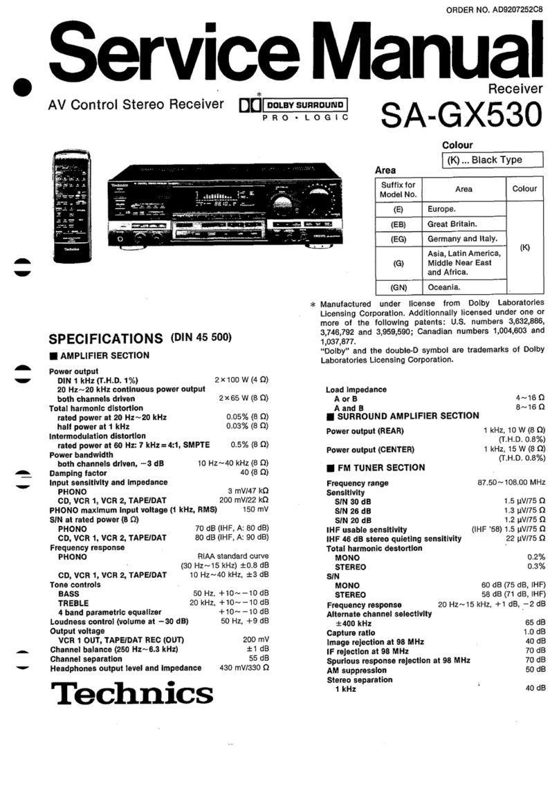
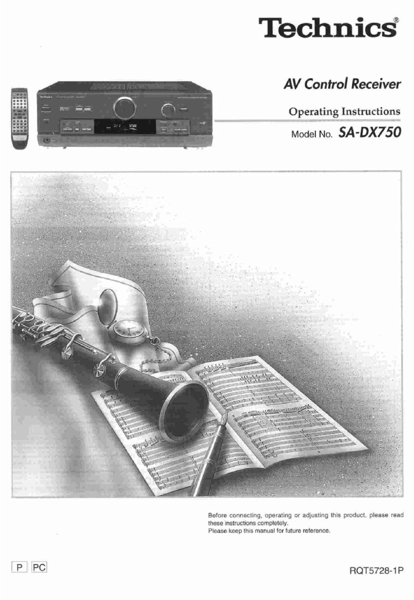
  9. Technics SA-DX750 User manual

Technics SA-DX750 User manual

Other manuals for SA-DX750

3

Other Technics Receiver manuals

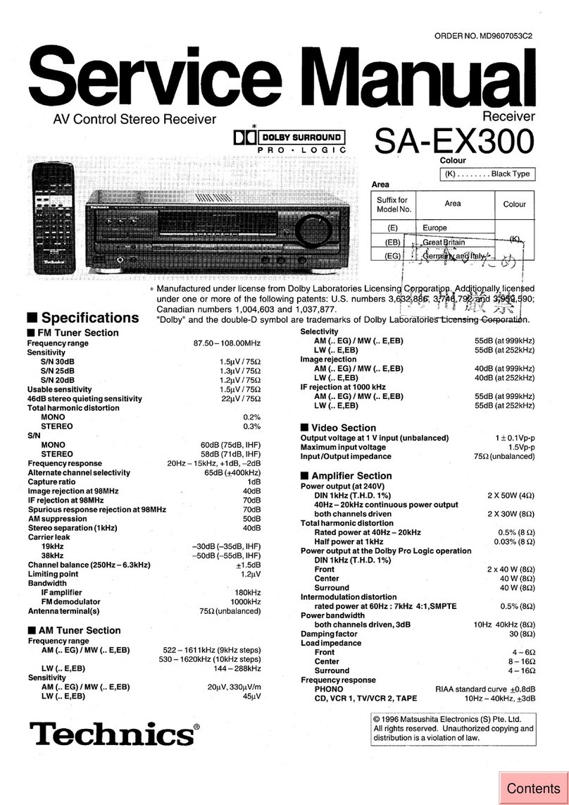
Technics SA-6000X User manual

Technics

Technics SA-6000X User manual

Technics SA-GX530 User manual

Technics

Technics SA-GX530 User manual

Technics SA-EX320 User manual

Technics

Technics SA-EX320 User manual

Technics SA-AX920 User manual

Technics

Technics SA-AX920 User manual

Technics SA-DA10 User manual

Technics

Technics SA-DA10 User manual

Technics SA-DX750 User manual

Technics

Technics SA-DX750 User manual

Technics SA-C100 User manual

Technics

Technics SA-C100 User manual

Technics SA-GX350 User manual

Technics

Technics SA-GX350 User manual

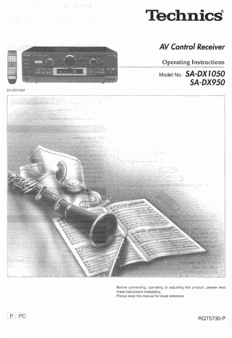
Technics SA-DX1050 User manual

Technics

Technics SA-DX1050 User manual

Technics SA-DX750 User manual

Technics

Technics SA-DX750 User manual

Technics SA-DX1050 User manual

Technics

Technics SA-DX1050 User manual

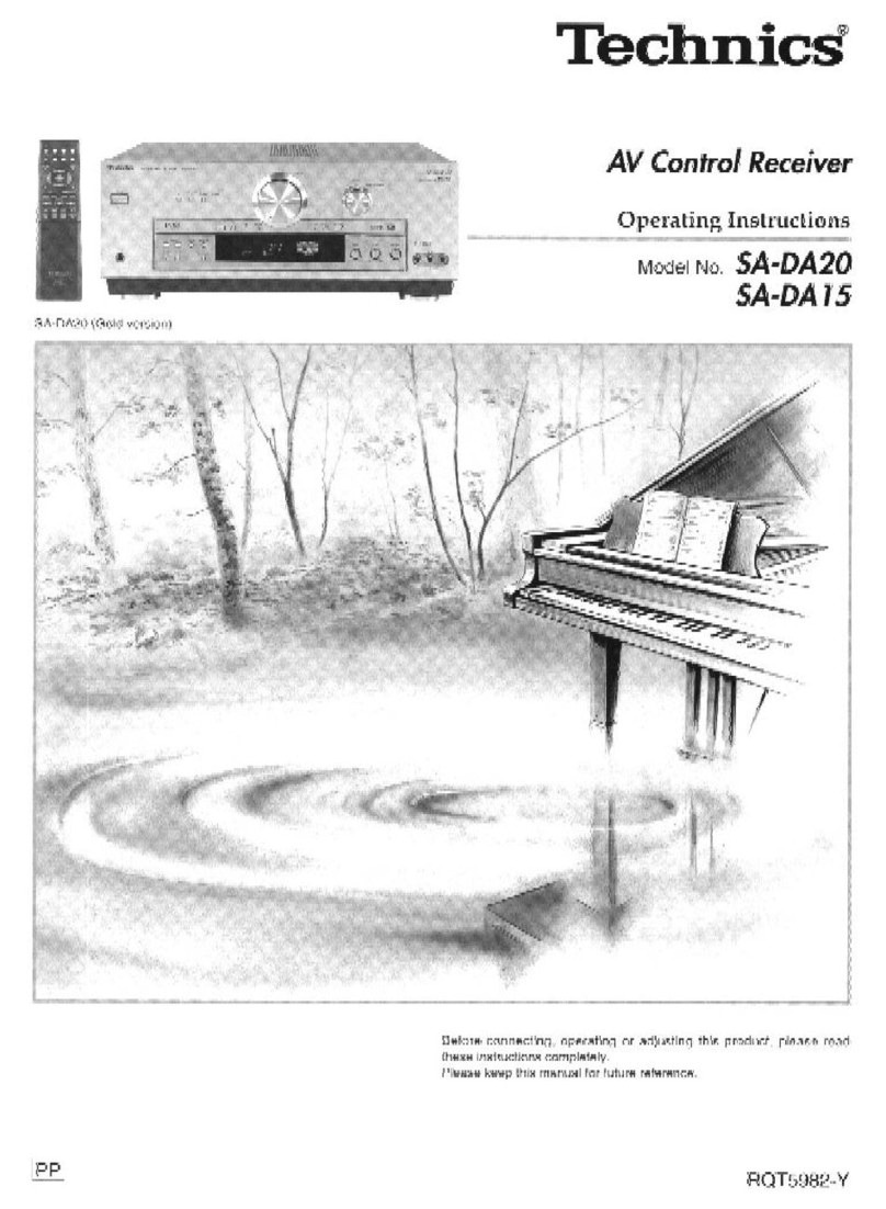
Technics SA-DA15 Quick start guide

Technics

Technics SA-DA15 Quick start guide

Technics SA-DX850 User manual

Technics

Technics SA-DX850 User manual

Technics SA-T670KFP User manual

Technics

Technics SA-T670KFP User manual

Technics SA-DA15N Operating User manual

Technics

Technics SA-DA15N Operating User manual

Technics SA-TX50 User manual

Technics

Technics SA-TX50 User manual

Technics SA-GX130D User manual

Technics

Technics SA-GX130D User manual

Technics SA-GX550 User manual

Technics

Technics SA-GX550 User manual

Technics SA-TX50 User manual

Technics

Technics SA-TX50 User manual

Technics SA-GX770 User manual

Technics

Technics SA-GX770 User manual

Technics SA-DA15 Building instructions

Technics

Technics SA-DA15 Building instructions

Technics SA-GX670 User manual

Technics

Technics SA-GX670 User manual

Technics SAEX310 - RECEIVER User manual

Technics

Technics SAEX310 - RECEIVER User manual

Technics SA-EX300 User manual

Technics

Technics SA-EX300 User manual

Popular Receiver manuals by other brands

Televes ZAS HD SAT user manual

Televes

Televes ZAS HD SAT user manual

Realistic DX-75 Operating and service instructions

Realistic

Realistic DX-75 Operating and service instructions

Saris 4620 Assembly instructions

Saris

Saris 4620 Assembly instructions

Mini DTR 206C PVR user manual

Mini

Mini DTR 206C PVR user manual

RF Elements TwistPort manual

RF Elements

RF Elements TwistPort manual

Denon DN-200WS user guide

Denon

Denon DN-200WS user guide

Yamaha RX-V467 owner's manual

Yamaha

Yamaha RX-V467 owner's manual

Russound SaphIR 858 instruction manual

Russound

Russound SaphIR 858 instruction manual

Quasonix RDMS Firmware update procedure

Quasonix

Quasonix RDMS Firmware update procedure

Pioneer XV-HTD1 Service manual

Pioneer

Pioneer XV-HTD1 Service manual

ATZ HDMI-V2-44HE150 manual

ATZ

ATZ HDMI-V2-44HE150 manual

Sony XNV-770BT MyTomTom Specifications

Sony

Sony XNV-770BT MyTomTom Specifications

Grundig STR 7122 TWIN Service manual

Grundig

Grundig STR 7122 TWIN Service manual

Creative Blaster Modem user guide

Creative

Creative Blaster Modem user guide

Panduit ATLONA AT-OME-RX11 installation guide

Panduit

Panduit ATLONA AT-OME-RX11 installation guide

VOLTCRAFT UTPS-40 operating instructions

VOLTCRAFT

VOLTCRAFT UTPS-40 operating instructions

JVC KW-ADV794 instructions

JVC

JVC KW-ADV794 instructions

Litelink VT-1001 operating instructions

Litelink

Litelink VT-1001 operating instructions

manuals.online logo
manuals.online logoBrands
  • About & Mission
  • Contact us
  • Privacy Policy
  • Terms and Conditions

Copyright 2025 Manuals.Online. All Rights Reserved.

Technics”
AV Control Receiver
Operating Instructions
MO~I
No SA-Dx750
Before connecting, operating or adjusting this product, please read
these instructions completely
Please keep this manual for future reference
RQT5728-P
Dear customer
Table of contents
Thank you for purchasing this product
For optimum performance and safety, please read these
instructions carefully
Listening caution
PRECAUTIONS
Control reference guide
Supplied accessories
Please check and identify the supplied
accessories
0 AC power supply cord (RJA0065-A) 1
0 AM loop antenna set (RSA0012) 1
(AM loop antenna, antenna holder, screw)
0 FM indoor antenna (RSA0006) 1
0
Batteries 2
@ >
0 Remote control (EUR7702020) 1
Refer to the separate booklet, “Remote Control”, for remote
control operation details
Use the numbers indicated in parentheses when asking for
replacement parts
(Only for U.S.A.)
To order accessories contact l-800-332-5368 or web site
(http://www.panasonic corn).
User memo
DATE OF PURCHASE
DEALER NAME
DEALER ADDRESS
TELEPHONE NUMBER I
The model number and serial number of this product can be
found on either the back or the bottom of the unit
Please note them in the space provided below and keep for
future reference
MODEL NUMBER SA-DX750
SERIAL NUMBER
Connections 6
Connecting video equipment 6
Connecting audio equipment 7
Connecting digital equipment 7
Antenna connections 8
Connecting the AC power supply cord and other information 9
Speaker connections 10
Placement of speakers 10
Connecting speakers 10
Customizing your receiver
Basic steps
Adjusting speaker output level
DSP sound modes
STEREO mode
SURROUND mode
SFC modes
Enjoying the sounds
Adjusting the tone and balance
Using headphones
Muting the volume
Adjusting the subwoofer level.
Using the TAPE MONITOR
15
15
16
17
18
18
19
19
19
The radio 20
Manual tuning 20
Preset tuning 21
Making a recording 22
The HELP function 22
Specifications 23
Maintenance 23
Product Service 23
Troubleshooting guide 24
Servicenter List (U.S.A.) 25
Warranty (U.S.A.) 26
CAUTION
Do not place anything on top of this unit or block the heat
radiation vents in any way In particular, do not place tape decks
or CD/DVD players on this unit as heat radiated from it can
damage your software
Selecting fine audio equipment such as the unit you’ve just
purchased is only the start of your musical enjoyment Now it’s time
to consider how you can maximize the fun and excitement your
equipment offers This manufacturer and the Electronic Industries
Association’s Consumer Electronics Group want you to get the most
out of your equipment by playing it at a safe level One that lets the
sound come through loud and clear without annoying blaring or
distortion-and, most importantly, without affecting your sensitive
hearing
We recommend you to avoid prolonged exposure to excessive
noise
Sound can be deceiving Over time your hearing “comfort level”
adapts to higher volumes of sound So what sounds “normal” can
actually be loud and harmful to your hearing
Guard against this by setting your equipment at a safe level
BEFORE your hearing adapts
To establish a safe level
l
Start your volume control at a low setting
l
Slowly increase the sound until you can hear it comfortably and
clearly, and without distortion
Once you have established a comfortable sound level
l
Set the dial and leave it there
Taking a minute to do this now will help to prevent hearing
damage or loss in the future After all, we want you listening for a
lifetime
- THE FOLLOWING APPLIES ONLY IN THE U S A -
CAUTION:
This equipment has been tested and found to comply with the
limits for a Class B digital device, pursuant to Part 15 of the
FCC Rules
These limits are designed to provide reasonable protection
against harmful interference in a residential installation This
equipment generates, uses and can radiate radio frequency
energy and, if not installed and used in accordance with the
instructions, may cause harmful interference to radio
communications However, there is no guarantee that
interference will not occur in a particular installation If this
equipment does cause harmful interference to radio or television
reception, which can be determined by turning the equipment off
and on, the user is encouraged to try to correct the interference
by one or more of the following measures
l
Reorient or relocate the receiving antenna
0 Increase the separation between the equipment and receiver
@Connect the equipment into an outlet on a circuit different
from that to which the receiver is connected
l
Consult the dealer or an experienced radionV technician for
help
Any unauthorized changes or modifications to this equipment
would void the user’s authority to operate this device
This device complies with Part 15 of the FCC Rules Operation
is subject to the following two conditions (1) This device may
not cause harmful interference, and (2) this device must accept
any interference received, including interference that may cause
undesired operation
WARNING:
TO REDUCE THE RISK OF FIRE, ELECTRIC
SHOCK OR PRODUCT DAMAGE, DO NOT
EXPOSE THIS APPLIANCE TO RAIN,
SPLASHING, DRIPPING OR MOISTURE.
CAUTION:
TO PREVENT ELECTRIC SHOCK MATCH WIDE
BLADE OF PLUG TO WIDE SLOT, FULLY
INSERT.
CAUTION TO REDUCE THE RISK OF ELECTRIC
SHOCK, DO NOT REMOVE SCREWS
NO USER-SERVICEABLE PARTS
INSIDE
REFER SERVICING TO QUALIFIED
SERVICE PERSONNEL
AL
The lightning flash with arrowhead symbol, within
an equilateral triangle, is intended to alert the user
to the presence of uninsulated “dangerous voltage”
within the products enclosure that may be of suffi-
cient magnitude to constitute a risk of electric shock
to persons
AL
The exclamation point within an equilateral triangle
is intended to alert the user to the presence of
important operating and maintenance (servicing)
instructions in the literature accompanying the ap-
pliance
Before using this unit please read these operating instructions
carefully Take special care to follow the warnings indicated on the
unit itself as well as the safety suggestions listed below
Afterwards keep them handy for future reference
Power Source
- The unit should be connected to power
supply only of the type described in the operating instructions or
as marked on the unit
Polarization
- If the unit is equipped with a polarized AC power
plug (a plug having one blade wider than the other), that plug
will fit into the AC outlet only one way This is a safety feature If
you are unable to insert the plug fully into the outlet, try
reversing the plug If the plug should still fail to fit, contact your
electrician to replace your obsolete outlet Do not defeat the
safety purpose of the polarized plug
Power Cord Protection
- AC power supply cords should be
routed so that they are not likely to be walked on or pinched by
items placed upon or against them Never take hold of the plug
or cord if your hand is wet, and always grasp the plug body
when connecting or disconnecting it
Nonuse Periods
- When the unit is not used, turn the power
off When left unused for a long period of time, the unit should
be unplugged from the household AC outlet
I
Environment I
1 Outdoor Antenna Grounding
- If an outside antenna is
connected to the receiver, be sure the antenna system is
grounded so as to provide some protection against voltage
surges and built-up static charges Section 810 of the National
Electrical Code, ANSVNFPA No 70-l 990, provides information
with respect to proper grounding of the mast and supporting
structure, grounding of the lead-in wire to an antenna discharge
unit, size of grounding conductors, location of antenna-
discharge unit, connection to grounding electrodes, and
requirements for the grounding electrode See figure below
GROUN
CLAMP
ANTENNA
LEAD IN
WIRE
$
\ y GROiJND CLAMPS
\
POWER SERVICEGROUNDING
ELECTRODE SYSTEM
(NEC ART 250, PART H)
NEC-NATIONAL ELECTRICAL CODE
2 Water and Moisture -
Do not use this unit near water-for
example, near a bathtub, washbowl, swimming pool, or the like
Damp basements should also be avoided
3 Heat
- The unit should be situated away from heat sources
such as radiators and the like
It also should not be placed in temperatures less than 5°C
(41 “F) or greater than 35°C (95°F)
Placement
Ventilation
- The unit should be situated so that its location or
position does not interfere with its proper ventilation Allow
10 cm (4”) clearance from the rear of the unit
Foreign Material
- Care should be taken so that objects do not
fall into and liquids are not spilled into the unit Do not subject
this unit to excessive smoke, dust, mechanical vibration, or
shock
Magnetism
-The unit should be situated away from equipment
or devices that generate strong magnetic fields
Stacking -
Do not place heavy objects, other than system
components, on top of the unit
Surface
- Place the unit on a flat, level surface
Carts and Stands
- The unit should be used only with a cart or
stand that is recommended by the manufacturer
The unit and cart combination should be moved
with care Quick stops, excessive force, and
uneven surfaces may cause the unit and cart
combination to overturn
Wall or Ceiling Mounting -
The unit should not be mounted to
a wall or ceiling, unless specified in this operating instructions
Clean the cabinet, panel and controls with a soft cloth lightly
moistened with mild detergent solution
Do not use any type of abrasive pad, scouring powder or solvent
such as alcohol or benzine
1 Damage Requiring Service
- The unit should be serviced by
qualified service personnel when
(a) The AC power supply cord or the plug has been damaged, or
(b) Objects have fallen or liquid has been spilled into the unit, or
(c) The unit has been exposed to rain, or
(d) The unit does not appear to operate normally or exhibits a
marked change in performance, or
(e) The unit has been dropped, or the enclosure damaged
2 Servicing -
The user should not attempt to service the unit
beyond that described in the operating instructions All other
servicing should be referred to an authorized service personnel
For the address of an authorized servicenter:
In the U S A , call l-800-21 l-7262 or visit www panasonic corn
In Canada, call 905-624-5505 or visit www panasonic ca
Reference pages are given in parentheses
I
Main unit I
I
Display section I
@ Standby/on button [POWER, 6/l] (13)
Press to switch the unit from on to standby mode or vice versa
In standby mode, the unit is still consuming a small amount of
power
@ Speaker on/off button [SPEAKERS]
@ Help/reset button [-HELP/-RESET]
@ DSP sound mode select button
(14917)
(22)
[DSP SOUND MODE] (13,17)
@ SFC mode select button [SFC MODE] (13,17)
@ Memory button [MEMORY]
(21)
0 Volume control [VOLUME] (17)
@I Input selector [INPUT SELECTOR] (13, 17)
@I Digital input select button/indicator [DIGITAL INPUT] (17)
@9 Subwoofer level button [SUBWOOFER LEVEL] (19)
@ Headphone jack [PHONES]
(18)
@ Tuning buttons [TUNING, V, A]
(20)
@ Preset channel button [PRESET]
(21)
@ Band select button [BAND]
(20)
@ FM mode select button [FM MODE]
(20)
@ Display section
0 Tape monitor button [TAPE MONITOR] (1%
@ Tone and balance select button
[BASS/TREBLE, BALANCE] (18)
@ Tape monitor indicator (19)
@ Tone and balance adjust buttons [-, +, L, R]
(18)
@ Display
@ Frequency unit indicators [kHz, MHz]
@ Program format indicators [L, C, R, LS, S, LFE, RS]
@ Front speaker indicator [-SPEAKERS-]
@ Stereo indicator [STEREO]
@ Monaural indicator [MONO]
@ Memory indicator [m]
@ Tuned indicator [TUNED]
@ Signal format indicators
(20)
(17)
(17)
(20)
(20)
(21)
(20)
[FIXED, PCM, 00 DIGITAL, 00 PRO LOGIC]
@ DSP sound mode indicators
[-SOUND MODE-, SFC, STEREO, SURROUND]
(17)
(17)
Refer to the separate booklet,“Remote Control”, for a guide to the
remote control’s buttons
Video connection cable
To connect equipment, refer to the appropriate operating
instructions m
l
Turn off all components before making any connections
Peripheral equipment and cables sold separately unless otherwise
l
Use digital connection to enjoy Dolby Digital (+ page 17)
indicated
l
Use analog connection to enjoy sources that cannot be decoded
on this unit and to record a source (N pages 15 and 22)
VIDEO OUT
fiF
- -’
AUDIO OUT
OUT
TV or monitor
Optical fiber cable
4
Coaxial cable
CD player
OUTPUT - -
Tape deck
If you have a graphic equalizer, connect it to the TAPE terminals page 19)
Satellite receiver, etc
Optical fiber cable connection
Dust cap
l
Do not bend the optical fiber cable
l
If the digital optical connector is not
going to be used, be sure to attach
the dust cap to prevent exposure to
dust
This unit cannot decode Dolby Digital
RF (radio frequency) signals from a
laser disc player
change the se~~ngsf-b pages f 2-13f.
CD player
=h”-l~s$
DIGITAL
OUT ‘I -
DVD player
I
OUT Iv
I
-’
FM
antenna
Fix the other end of the antenna where
reception is best
FM indoor antenna (included)
c
Adhesive tape
When mounting the antenna
to a column, wall or rack
II
FM
AM loop antenna (included)
AM
loop antenna
l
Fit the AM loop antenna holder
(included) onto the rear panel of
this unit and then attach the AM
loop antenna to it (facing in the
direction of best reception)
@Keep the antenna cord away
from tape decks, DVD players,
and other cords
To connect an outdoor antenna
FM outdoor antenna
l
Disconnect the FM indoor antenna
l
The antenna should be installed by a competent technician
l
Twist the coaxial cable’s shield braid firmly and connect it to the
GND terminal
AM outdoor antenna
l
Run a piece of vinyl wire horizontally across a window or other
convenient location
l
Leave the loop antenna connected
l
Disconnect the antenna when the unit is not in use Do not use
the antenna during an electrical storm
FM outdoor anntena
75 R coaxial cable
20 mm (25/32”:
Shield braid
+
10 mm (3/B”)
[ Core wire
Vinyl-covered wire
._-_ -5-12 m-
(16-40 ft)
“SWITCHED” AC outlet
Power to the outlet is controlled by the power switch of this unit
Audio equipment rated up to a maximum of 80 W can be
connected here If equipment exceeding this rating is connected,
the outlet may be rendered inoperable Consult your dealer to
replace the fuse
AC power supply cord
Conserving power
The unit consumes 1 W even when it is turned off with [POWER, &/I]
To save power when the unit is not to be used for a long time, unplug it
from the household AC outlet
If the unit is left unplugged for longer than a few weeks, all settings will
revert to the factory settings Do the settings again if this occurs
Household AC outlet
(AC 120 V/60 Hz)
’ (included)
-1
cords are connected
The included AC power
supply cord is for use with this
unit only Do not use it with
other equipment
ker
CQ
ns
Center speaker
I-&
Front speaker
(left)
Surround speaker ’
(left)
120”
$urround speaker
(right)
The front, center, and surround-speakers should be placed at
approximately the same distance from the seating area The angles
in the diagram are approximate.
,Ij ,,___ I I
Front speakers
Place on the left and right of the TV at seated ear height so that
there is good coherency between the picture and sound
Center speaker
Place underneath or above the center of the TV Aim the speaker at
the seating area
Surround speakers
Place on the side of or slightly behind the seating area, about one
meter higher than ear level
Subwoofer
The subwoofer can be placed in any position as long as it is at a
reasonable distance from the TV
Note that some experimentation can yield the smoothest low
frequency performance Placement near a corner can increase the
apparent output level, but can result in unnatural bass
Other connections are possible depending on your speaker system
See your speaker system’s operating instructions for details
I
Front speakers I
1Speaker impedance:
6-8 n 1
Front speaker
(right) Front speaker
(left) I----
Speaker cabl