manuals.online logo
Brands
  1. Home
  2. •
  3. Brands
  4. •
  5. Technics
  6. •
  7. Stereo Receiver
  8. •
  9. Technics SA-AX920 User manual

Technics SA-AX920 User manual

AV ControlStereoReceiver
SA-AX920
SA-AX720
Operating Instructions
The photographs show SA-AX920.
Dear Customer
Thank you for purchasing this Technics product.
For optimum performance and safety, please read these
instructions carefully.
i
These operating instructions are applicable to models SA- I
I
AX920 and SA-AX720, however, are intended primarily for
model SA-AX920.
Tableof contents
Precautions ..................................................................................3
Supplied accessories ................................................................4
Listening caution ........................................................................4
Concerning the remote control ..............................................5
Front panel controls ..................................................................6
Equipment connections ...........................................................7
Antenna connections ..............................................................10
Speaker connections ..............................................................12
Basic operations ...................................................................... 16
To adjust the tone quality ............................................................ 18
To adjust the sound balance ....................................................... 18
To mute the sound level .............................................................. 18
To listen through headphones ....................... _............................. 18
To compensate when the volume is low _ ......... 19
When using the VCR 2 terminals (front side)
......................................................................... 19
Listening to radio broadcasts ........................................... :.20
Sequential tuning ........................................................................ :20
Direct tuning ................................................................ 21
Preset tuning ............................................................................... 22
Enjoying sound with DOLBY PRO LO__
Setting the center mode and adjusting spe_....25
Adjusting the delay time ........................................................... .--..27
Enjoying SURROUND or 3 STEREO .................................. ._.=:28
Enjoying sound with SFC ...................................................... 29
Adjusting field of sound ............................................................... 30.
Enjoying sound with 6 channel discret_._: ........32
Making a recording ......................................................... __...'_...-33_
Recording on a tape deck............................................. 3_
Recording on a VCR .................................................................... 33
About the HELP function ....................................................... 34
Product service ........................................................................34
Troubleshooting guide ...........................................................35
Technical specifications .......................................Back cover
CAUTION
Do not place a tape deck or CD player on top of this unit.
Heat radiated from the top of this unit may cause damage to the
tape or CD s0ft_are.
NO
User memo:
DATE OFPURCHASE
DEALER NAME
DEALER ADDRESS
TELEPHONE NUMBER
The model number and serial number of this product can be
found on either the back or the bottom ofthe unit.
Please note them in the space provided below and keep for
future reference.
MODEL NUMBER ....................... :............................. ...................
SERIAL NUMBER ......................................................................
THE FOLLOWING APPLIES ONLY IN THE U.S.A.
AUTION:
ny unauthorized changes or modifications to this
quipment would void the user's authority to operate this
vlce.
WARNING:
TO REDUCE THE RISK OF FIRE, ELECTRIC
SHOCK OR PRODUCT DAMAGE, DO NOT
EXPOSE THIS APPLIANCE TO RAIN,
SPLASHING,DRIPPING OR MOISTURE.
CAUTION:
TO PREVE_ SHOCK MATCH WIDE
B_DE WIDE SLOT, FULLY
-- t_ _','_ _"` ....
T,o P_EDUCE THE RISK OF ELECTRIC
_SH(_CK, DO NOT REMOVE SCREWS.
NO USER-SERVICEABLE PARTS
INSIDE.
REFER SERVICING TO QUALIFIED
SERVICE PERSONNEL.
The lightning flash with arrowhead symbol, within
an equilateral triangle, is intended to alert the user
to the presence of uninsulated "dangerous voltage"
within the product's enclosure that may be of
sufficient magnitude to constitute a dsk of electric
shock t'o persons.
The exclamation point within _ulfateral triangle
is intended to alert the user to the presence of
important operating and maintenance (servicing)
instructions in the literature accompanying the
appliance.
Before using this unit please read these operating instructions
carefully. Take special care to follow the warnings indicated on the
unit itself as well as the safety suggestions listed below.
Afterwards keep them handy for future reference.
1. Power Source - The unit should be connected to power supply
only of the type described in the operating instructions or as
marked on the unit.
2. Polarization - If the unit is equipped with a polarized AC power
plug (a plug having one blade wider than the other), that plug
will fit into the AC outlet only one way. This is a safety
feature. If you are unable to insert the plug fully into the outlet,
try reversing the plug. If the plug should still fail to fit, contact
your electrician to replace your obsolete outlet. Do not defeat
the safety purpose of the polarized plug.
3. Power Cord Protection - AC power supply cords should be
muted so that they are not likely to be walked on or pinched by
items placed upon or against them. Never take hold of the plug
or cord if your hand is wet, and always grasp the plug body
when connecting or disconnecting it.
4. Nonuse Periods - When the unit is not used, tum the power
off. When left unused for a long period of time, the unit should
be unplugged from the household AC outlet.
1. Ventilation - The unit should be situated so that its location or
position does not interfere with its proper ventilation. Allow 10 cm
(4") clearance from the rear of the unit.
2. Foreign Material - Care should be taken so that objects do not
fall into and liquids are not spilled into the unit. Do not subject
this unit to excessive smoke, dust, mechanical vibration, or
shock.
3. Magnetism - The unit should be Situated.away from equipment
or devices that generate strong magnetic fields.
4. Stacking -- Do not place heavy objects, other than system
components, on top of the unit.
5. Surface - Place the uniton a fiat, level surface.
6. Carts and Stands - The unit should he used only with a cart or
stand that is recommended by the manufacturer. The unit and
cart combination should be moved with care.
Quick stops, excessive force, and uneven sur-
faces may cause the unit and cart combination
to overtum.
7. Wall or Ceiling Mounting - The unit should no( be mounted to
a wall or ceiling, unless specified in this operating instructions.
a)
IEnvironment
1. I
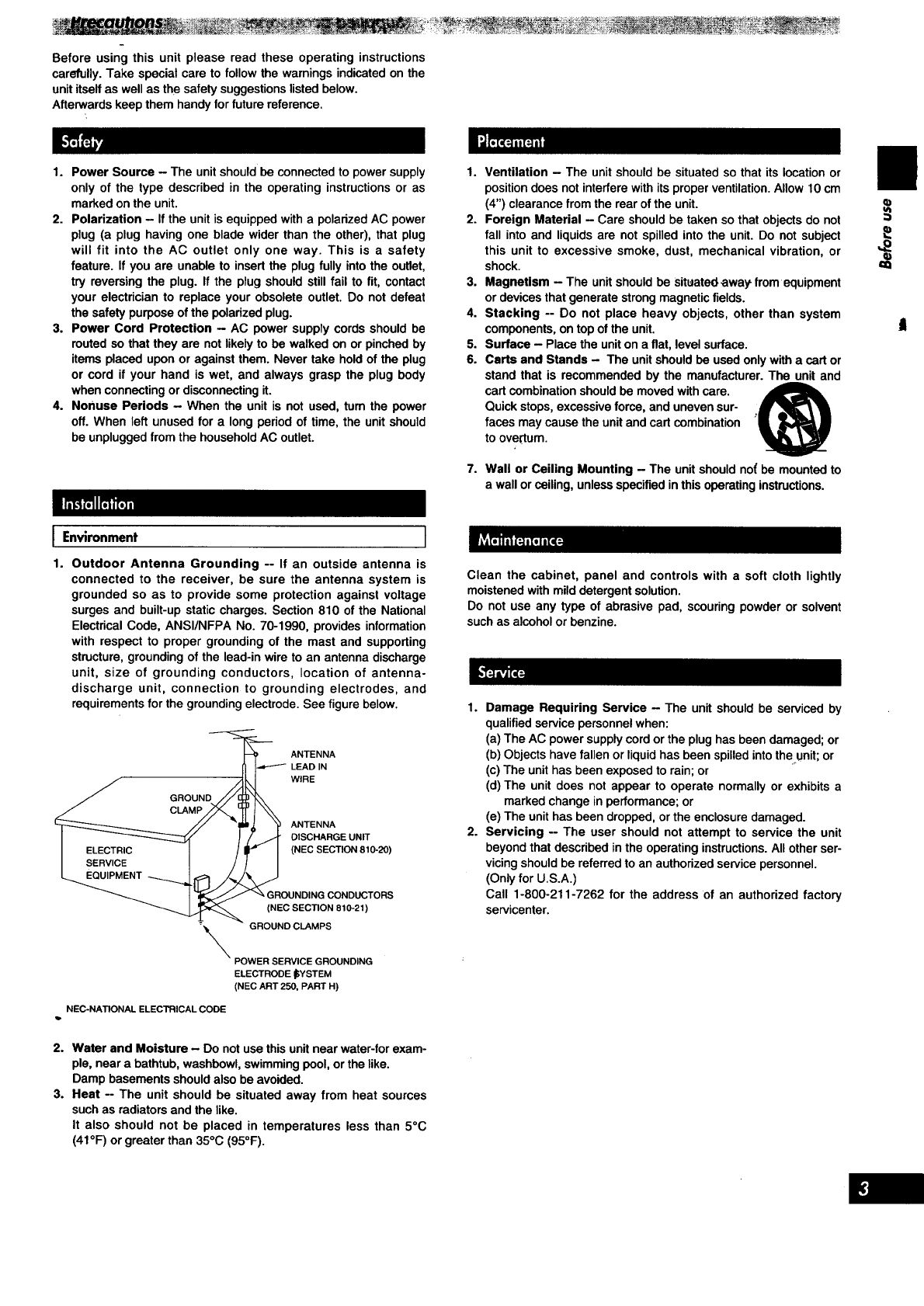
Outdoor Antenna Grounding -- If an outside antenna is
connected to the receiver, be sure the antenna system is
grounded so as to provide some protection against voltage
surges and built-up static charges. Section 810 of the National
Electrical Code, ANSI/NFPA No. 70-1990, provides information
with respect to proper grounding of the mast and supporting
structure, grounding of the lead-in wire to an antenna discharge
unit, size of grounding conductors, location of antenna-
discharge unit, connection to grounding electrodes, and
requirements for the grounding electrode. See figure below.
"__ ANTENNA
_I I""-"_ LEADIN
/GROUND //[_3
// "pill _ y ANTENNA
I_/ /. _]_ OlSCHARGEUNIT
_uGIViCE_NT -_/:_ ._ (NEC SECTION 810-20)
I_" GROUNDING CONDUCTORS
_IEC SECTION 810-21)
\ :::::::::::::::::::::
ELECTRODE _YSTEM
(NEC ART 250, PART H)
NEC-NATIONAL ELECTRICAL CODE
2. Water and Moisture - Do not use this unit near water-for exam-
ple, near a bathtub, washbowl, swimming pool, or the like.
Damp basements should also be avoided.
3. Heat -- The unit should be situated away from heat sources
such as radiators and the like.
It also should not be placed in temperatures less than 5°C
(41°F) or greater than 35°C (95°F).
Clean the cabinet, panel and controls with a soft cloth lightly
moistened with mild detergent solution.
Do not use any type of abrasive pad, scouring powder or solvent
such as alcohol or benzine.
1. Damage Requiring Service - The unit should be serviced by
qualified service personnel when:
(a) The AC power supply cord or the plug has been damaged; or
(b) Objects have fallen or liquid has been spilled into the unit; or
(c) The unit has been exposed to rain; or
(d) The unit does not appear to operate normally or exhibits a
marked change in performance; or
(e) The unit has been dropped, or the enclosure damaged.
2. Servicing -- The user should not attempt to service the unit
beyond that described in the operating instructions. All other ser-
vicing should be referred to an authorized service personnel.
(Only for U.S.A.)
Call 1-800-211-7262 for the address of an authorized factory
servicenter.
/q)
Please check and identify
the supplied accessories.
,oooHoo.ooooo...oooo...ooooo.oooo ...ooo.oooooo.ooooo.. Hoooo.. Ho-.ooo..o-ooooo
[3®
oo_o_o_e_Q_j_O_eeoe_ooeeo_ooe_o_*oeoeo_o_o_0o_'
.°°°°°°°°°°°°°oo°°°o°°°°°°°°°°°°°°°°°°°.°°o°°°°°°°°°°°°°°°°°°.°°°°°°°°°°°° °°°°°o
D®
oooe=_______oI_oe______0ee_ee=____o_oooeeee____eoe_eo_eo__o_Deeoe______oeeoeo=o.
De ,)
)
_________________=o_________Q_o_e______________________e___________=____________
F-I
(RAK-SA937MK)
(EUR646463)
_) AC power supply cord (SJA172) ............................................ 1 pc.
(_)AM loop ar_enna set (RSA0010)
•AM loop antenna ................................................................. 1 pc.
• AM loop antenna holder ...................................................... 1 pc.
•Screw .................................................................................. 1 pc.
_) FM indoor antenna (RSA0006) .............................................. 1 pc.
(_ Batteries ............................................................................... 2 pcs.
(_)Remote control transmitter .................................................... 1 pc.
Use numbers indicated in parentheses when asking for replacement
parts. . ,.................
(Only for U.S.A.)
To order accessories call PASC Accessory Dept. 1-800-211-7262.
Selecting fine audio equipment such as the unit you've just pur-
chased isonly the start of your musical enjoyment. Now it's time to
consider how you can maximize the fun and excitement your equip-
ment offers. This manufacturer and the Electronic Industries
Association's Consumer Electronics Group want you to get the most
out of your equipment by playing it at a safe level. One that lets the
sound come through loud and clear without annoying blaring or dis-
tortion-and, most importantly, without affecting your sensitive hear-
ing.
We recommend you to avoid prolonged exposure to excessive
noise.
Sound can be deceiving. Over time your hearing "comfort level"
adapts to higher volumes of sound. So what sounds "normal" can
actually be loud and harmful to your hearing.
Guard against this by setting your equipment at a safe level
BEFORE your hearing adapts.
To establish a safe level:
•Start your volume control at a low setting.
•Slowly increase the sound until you can hear it comfortably and
clearly, and without distortion.
-Once you have established a comfortable sound level:
• Set the dial and leave it there.
Taking a minute to do this now will help to prevent hearing damage
or loss in the future. After all, we want you listening for a lifetime.
\
(®, ®).
oooooooooooooooooooo.,ooo°,ooo.oo.,.oo,,.ooo,..ooooooooooo,oooooo..,o0
Insert the batteries in the
correct polarities ((_, O).
o.o.oooooo,ooooooooooo,,oo.o,ooo.o,o,oooo,..ooooooooooo,ooooo,oo=o**ooooooo
r_ Remote control signal sensor
D ....
Transmission
window
Avoid any obstacles
ooo1-11
About 7 meters (23 feet) in
front of the signal sensor.
(1"heactual range will
depend on the angle at
which the remote control is
used.)
[]
•Thoroughly clean the battery compartment before inserting new
batteries.
•Do not mix old and new batteries, or batteries of different types
(carbon and alkaline, etc.).
•If you will not use the remote control for a long period of time,
remove the batteries and store them in a cool, dark place.
•Do not use rechargeable type batteries.
•Do not attempt to recharge alkaline or carbon batteries.
•Always remove old, weak or worn-out batteries promptly and dis-
pose of them properly.
•Never subject batteries to excessive heat or flame; do not attempt
to disassemble them; and be sure theY are not short-circuited.
•If the leaking electrolyte comes into c_)nt_'__ttfi "sl_in0r clothes,
flush with water immediately.
When you need to replace these batteries
UsetwoR6/LR6,AA, UM-3 batteries.
[]
Be sure the transmission window and the signal sensor are free
from dust. Excessive dust might effect performance.
The operation may not be correct if direct sunlight or other strong
light source strikes the signal sensor of this unit. If there is a prob-
lem, place the unit away from the light source.
==
t
(_)Power "STANDBY _/ON" switch
(POWER, STANDBY _/ON)
Press to switch the unit from on to standby mode or vice versa.
In standby mode, the unit is still consuming a small amount of
power.
Speaker select buttons (SPEAKERS A, B)
(_) Dolby Pro Logic mode/SFC indicator
(_ Dolby Pro Logic mode/SFC selector
(_ SFC mode selector (MODE)
(_) Input indicator
(_ DVD 6ch input indicator
(_) DVD 6ch input select button (DVD 6CH INPUT)
(_ Input selector (INPUT SELECTOR)- ....
(_) Muting button (MUTING)
_) Volume control (VOLUME)
(_ Help/reset button (-HELP -RESET)
Headphones jack (PHONES)
@ Display
(_ Bass control (BASS)
Treble control (TREBLE)
VCR 2 input terminals (VCR 2)
VCR 2, TV/DSS input select button
( .,,_VCR 2, .=_TVIDSS)
Subwoofer level control (SUBWOOFER LEVEL)
_) Balance control (BALANCE)
Delay time adjust button (DELAY TIME)
Center mode select button (CENTER MODE)
Loudness ON/OFF button (LOUDNESS)
_)Tuning buttons (TUNING)
Radio station presetting button (PRESET)
Band select button (BAND)
_) FM mode select button (FM MODE)
Memory button (MEMORY)
Make sure that the power supply for all components has been turned off before making any connections.
To connect equipment, refer to the appropriate operating instructions.
IIIrRF3
Do not place books, etc., on the top of this unit or block the heat radiation vents in any way.
Stereo connection cable (not included)
White (L)
Red (R)
I'a'_i,k'Jr.,_-,,:_l
Only for turntable
with ground terminal
GND IOU]:PLJT
oll n_
Turntable (not included)
CD changer(orCD player)
(notincluded)
OUTPUT
PLAY (OU--_ :IEC (IN)
Tape deck (not included)
"SWITCHED" AC outlets
Power to the outlet is controlled by the power
switch of this unit. Audio equipment rated up
to TOTAL 80 W can be connected here.
There isonly one AC outlet.
The cooling fan operate,_ at
high power output levels only.
i
I I
Household AC outlet
(AC 120 V/60 Hz)
=@
AC power supply cord
(included)
Connect this cord only after I
all other cables and cords Iare connected.
..b
P
Stereo connection cable (not included)
White (L) _
Red (R) •
Video connection cable (not included)
AUDIO
IN
Laser disc player (not included)
f,I
IAUDIO
OUT TV (not ir_c!u..d_l)......
AUDIO
OUT
VIDEO
OUT VIDEO
IN '
AUDIO VIDEO
OUT IN
[.I-----I=
VCR (not included)
The "VCR 1" terminals shown in the illustration
corresponds respectively to the "VCR" terminals
on SA-AX720.
VIDEO
OUT
Connecting to the VCR 2 terminals on
the front panel
° Q
(
(R)
Camcorder, etc.
(not included)
OO O O
AUDIO
OUT
Stereoconnectingcable(notincluded)
White(L)_
Red (R)
Monaural connection cable (not included)
Video connection cable (not included)
/
O@
O@
@
0 O@ @@
i€.lOl0 _IT¢0
I I
Connecting a DVD player with 6 channel discrete output
tI AUDIO OUT DVD player
I(SUBWOOFER) (not included)
AUDIO OUT t
t2 I-I
AUDIO OUT VIDEO AUDIO OUT
(SURROUND OUT (FRONT L,R)
L,R)
I
Connecting a DVD player with 2 channel output
ooo
AUDIO
OUT
DVD player
(not included) VIDEO
D _ n
r......................................................................................................
You can enjoy 6 channel discrete sound by making
the below connections,
AUDIO OUT
(SUBWOOFER) o
_UD,OOUq
(CENTER) /
AUDIO OUT AC-3 decoder
(FRONT L,R) (not included)
iAUDIO OUT
(SURROUND DIGITAL
L,R) IN
I_ Optical
digital cable
L[ (not included) DIGITAL
OUT
oo kt r----_ I-L._._
VlDEOI I I_ ,.__..,
OUT I DVD player
I(not included)
L.......................................................... _ ................................. ":'
FM indoor antenna
(included)
AMloopantenna
(included)
®
AMANT
AMLOOPANT
Screw (included)
[]
This antenna is normally sufficient for reception of FM broadcasts.
Attach to a wall (using tape) facing in the direction of best reception.
For best reception
An FM outdoor antenna is recommended.
[]
ThisantennaisnormallysufficientforreceptionofAMbroadcasts,
Fit the AM loop antenna holder (included) onto the rear panel of this
unit and then attach the AM loop antenna to the AM loop antenna
holder (facing in the direction of best reception).
Pay attention to the following points when mounting the anten-
na.
•Do not mount it close to power cords, speaker wires or metal sur-
faces (Doing so will result in noise).
• Do not mount it close to a tape deck. When the t_pe deck isbeing
used, chirping or beeping sounds may result.
IWhen mounting the antenna to a column, a wall or rack [] I
Mount theantennaso thatthe hingeis vertical.
II .....
FM outdoor antenna
(not included)
75 _ coaxial cable
(not included)
(_) Remove a piece of the outer
vinyl insulator.
20 mm (25/a2")
(_) Twist the shield braid
to expose the core
wire.
Shield braid 10 mm (3/8")
(_) Connect the shield braid and the
core wire as shown at left.
.
AM AI_
AMLOOPANT
Vinyl-covered wire
(not included)
J ,
AM loop antenna
(included)
[]
An outdoor antenna should be used when using this unit in moun-
tainous areas or in spaces enclosed by reinforced concrete where
the FM indoor antenna (included) does not provide satisfactory
reception.
Disconnect the FM indoor antenna if an FM outdoor antenna is
installed.
An outdoor antenna should be installed by a qualified technician
only.
[]
An outdoor antenna should be used when using this unit in
mountainousareas or in spaces enclosedby reinforcedconcrete
wherethe AMloopantenna(included)doesnotprovidesatisfactory
reception.
Stretch 5-12 m (16-40 ft.) of vinyl-covered wire horizontally across
a window frame or other convenient location, keepihg it as high as
possible from the ground.
When the unit is not in use, disconnect the outdeor antenna to
prevent possible damage that may be caused by lightning. Never
use an outdoor antenna dudng an electrical storm.
Be sure to connect the AM loop antenna even when an outdoor
antenna is used.
Front speaker
(Left)
(not included)
Surround speaker
(Left)
(not included)
Center speaker Front speaker
(not included) (Right)
(not included)
•_ Subwoofer
(not included)
Surround speaker
(Right)
(not included)
For front speakers
Place the front left/right speakers at both the left and right sides of
the TV at seated ear height so that there is good coherency
between the picture and sound.
For center speaker
Place the center speaker underneath or above the center of the TV.
Aim the speaker such that it is pointed at the seating area.
For surround speakers
Place thesurround speakersonthe sideof orslightlybehindthe lis-
tener,and aboutonemeterhigherthanear!eve!,_
For subwoofer
The subwoofer can be placed in any position as long as it is at a
reasonable distance from the TV.
Note that some experimentation in placement of the subwoofer can
yield the smoothest low frequency performance. Placement near a
corner can increase the apparent output level, but can result in
unnatural bass.
/
O@
O@
O@
O@
00@
@OG
OOG
I I
i SUB-CENTER FRONT
SURROUND
i
i_'f,_V.,]):_P,To]
/
OG
OG
0G --G-G
U 00G
O'G
GOG
oOG
I I
i
i
GO ,=,=.
G_ ..... "'°
GG "':"J ........ i
@
SURROUND
t
WOOFER
OUT
CENTER FRONT
-....................................... •j._:.: .............................. •.....
m
Other connections are possible depending on the speaker system you
have.
For details, see the operating instructions that came with your speaker
system.
S. e,cob,e C÷
(not included) (_ (_
FConnecting the speaker cable
1
4,
C:::==::::_I=,.-
To prevent damage to circuitry, never
short-circuit positive (+) and negative
(-) speaker wires. ........
I Fr°ntspe°kers •I
i
To connect to the "A" terminals
Front speaker
(Right)
(not included)
f"%
Front speaker
(Left)
not included)
To connect to the "B" terminals
For connection to a second pair of speakers.
Front speaker
(Right)
(not included)
FRONT
Front speaker
(Left)
not included)
i,. J
.................................................................................
.Speaker impedance:
A or B:
A and B:
4-8
8Q A or B: 8
A and B: 8
JSurround speakers I
I_r_FJ
|Surround speaker Surround speaker
(Right) (Left)
(not included) (not included)
SURROUND
@
1. Before sound can be heard, both surround
speakers must be connected.
2. Do not connect the surround speakers to the
front speaker terminals. The surround speakers
may be damaged if connected to the front termi-
nals.
I Speaker impedance-: .........8_ ..... I
J Centerspeaker J
Center speaker
(not included) ISpeaker impedance: 8Q I
CENTER
@,=
ISubwoofer
To connect a subwoofer which has a built-in amplifier
Subwoofer withbuilt-in
amplifier (not included)
INPUT
Monaural-Stereo
convertercable
_Connections can be made in
the following ways as well.
(Ex.1) (Ex.2)
INPUT
LSUB-
WOOFER(
OUT
INPUT
,,,o,
connected
WOOFER
OUT )
E
i
To connect a subwoofer which does not have a built-in amplifier
Subwoofer
(not included)
SURROUND SUB-CENTER FRONT
SUB-
QWOOFER
OUT
ISpeaker impedance: 8 _I
This receiver has no amplifier section designed espe-
cially for the subwoofer.
To connect a subwoofer which does not
have a built-in amplifier
Connect an optional amplifier to the =SUBWOOFER
OUT" terminal of this unit and then connect a sub-
woofer to the speaker terminals of the amplifier.
.°..ooolo.o..=.°°.°°°°o°°.looooooo°..o...°.....°°°...°°.°°ooooooo=o..°oo,
ASPEAKERS8
%°
VOLUME
©
MIN MAX
Before operation, set VOLUME to the "MIN" position.
HPress POWER.
I_ Press A and/or B to select the speaker sys-
tem(s) to be used.
Aand B refer to the speaker terminals at the rear of the unit.
la
If the button is pressed once more, the indicator will switch off
and no sound will be heard from the speakers.
Turn INPUT SELECTOR to select and start
the desired source.
(Refer to the appropriate operating instructions for details.)
The indicator which corresponds to the selected input source
will illuminate.
VCR 1: To watch video tapes (VCR 1)
TV/DSS/VCR 2" To watch TV, DSS or video tapes (VCR 2)
DVD: To watch DVD
TAPE: To listen to cassette tapes
CD: To listen to compact discs
TUNER: To listen to radio broadcasts
PHONO: To listen to phono discs
The "VCR 1" and =TV/DSS/VCR 2" selectors correspond
respectivelytothe"VCR"and "TV/DSS"selectors.
If a Dolby Pro Logic or SFC mode has been select-
ed
After displaying the selected source, the display will then
change to show the Dolby Pro Logic or SFC mode.
If the source chosen was TUNER then the display will change
again to show the frequency.
The indicator (_) which corresponds to the selected mode
will light up.
To watch a video (or DVD) or the TV, set the TV to either the
TV mode or VIDEO mode as indicated below.
•To enjoy videos (or DVD)
Set it to VIDEO mode.
•To watch TV
Set it to TV mode.
For your reference
If you are using VCR and you select TAPE, CD, TUNER, or
PHONO, the picture will remain on the screen.
I_1 Turn VOLUME to adjust the volume level.
If using a subwoofer, adjust its volume with SUBWOOFER
LEVEL.
If the subwoofer isn't being used, be sure to set SUB-
WOOFER LEVELto MIN. _ ..-
!¥,q
,._ °°-° 060
]oo®O
OOQ o
I Whenusingspeakersunder8 _ []
Press A or B until LOW IMP lights up on the dis-
play.
I
If even one of the speakers being used has an impedance under
8Q, press and hold down either button Aor button B for 4 seconds
or more to set the impedance on the main unit to LOW.
(Press and hold down once again for 4 seconds or more to turn it
off.)
Note that When this indicator is illuminated, speakers A and B can-
not both be used at the same time.
To change a speaker: .....
e.g. To use speaker B press A (the _indi_ior goes 0ut), and then
press B to activate speaker B.
,.O*.H.HOHO*=,.....O...,,O,*=*O.......,.OeOO,=HOe=Q,=*,.OOO.,.,...... H......
Alter listening is finished
Be sure to reduce the volume level, and switch the power to the
standby condition by pressing POWER.
[]
Turn BASS to adjust the low frequency sound.
Turn TREBLE to adjust the high frequency sound.
[]
I
Turn BALANCE to adjust the left/right sound bal-
ance.
[]
Press MUTING.
The message =MUTING ON NOW" runs repeatedly from right to left
across the display as long as the muting function ison.
Press once again to return to the previous volume level.
mm
L R
B..............................................................
:
I- I I.._i I I ili/_.') , i/.._1
VOLUME
MIN MAX
(_) PHONES Headphones
(_ (not included)
When the receiver is turned off, the muting,operation will be
automaticallycancelled.
[]
(_)Use VOLUME to reduce the volume level.
(_)Connect the he_;dphones.
Plug type: 6.3 mm (1/4 in.) stereo
(_)Use VOLUME to adjust the volume level.
If you do not want sound from the speakers, press SPEAKERS but-
ton(s) and check the speaker indicator(s) goes out,
If a subwoofer is connected to your system, turn off the power to it
(or the subwoofer amp you are using) or lower the volume to the
minimum level.
If a subwoofer is connected to your system, silence it by turning the
SUBWOOFER LEVEL control on the receiver to MIN.
Avoid listening for prolonged periods of time to prevent hearing
damage.
[]
• ©
6
O0
1@@@0
000
LOUDNESS
..........................................................
__. VCR 2 /_
_i TV/DSS
This button balances low volume sounds by boosting bass sound
pressure.
Press LOUDNESS.
The message "ON" will appear on the display for 2 seconds.
When "ON", ")," will light up in the display.
To return to the previous condition, press once again.
The message "OFF-" will appear on the display for 2 seconds, then
"Ip" tums off.
[]
I,.
This. button can be used only when TV/DSSNCR 2 is selected as ,,L_.
the input source.
The VCR 2, TV/DSS input select button works for both TV/DSS
input and input from the source connected to the front side "VCR 2"
terninals. (See page 8.)
Set ".._ VCR 2" or "J. TV/DSS" position.
II
Use the tuning buttons to tune-in radio stations.
IBm Turn INPUT SELECTOR to select TUNER.
I_ Press BAND to select "FM" or "AM".
I[_ Press TUNING (V) or (^) to tune to the
desired frequency.
Tuning intervals FM: 0.2 MHz
AM: 10 kHz
=QUARTZ LOCK" lights up when tun_l_ .......
=STEREO" lights up when an FM stereo broadcast is
received.
To make an automatic search for stations
If TUNING (V) or (^) is held down for an instant until the fre-
quency begins to scroll, the broadcast stations are tuned in
automatically when one isfound.
Tuning may stop automatically if any jamming is encountered.
• ..°o°......,°°o....,°+..o i.o.°.eo.o.+..oo.o,.....°,,oo°°°...o ,,o,°°°°.o°..°°....
If noise is excessive in the FM stereo mode
Press FM MODE.
(The "STEREO" indicator will go out, and the "MONO" indicator will
lightup.)
The broadcast will be monaural, but noise will be reduced.
If the button is pressed once more, the stereo mode will be
resumed.

Other manuals for SA-AX920

1

This manual suits for next models

1

Other Technics Stereo Receiver manuals

Technics SH-AC500D User manual

Technics

Technics SH-AC500D User manual

Technics SA-AX910 User manual

Technics

Technics SA-AX910 User manual

Technics SA-GX550 User manual

Technics

Technics SA-GX550 User manual

Technics SA-GX230 User manual

Technics

Technics SA-GX230 User manual

Technics SF-DX7 User manual

Technics

Technics SF-DX7 User manual

Technics SA-GX130D User manual

Technics

Technics SA-GX130D User manual

Technics SA-DA10 User manual

Technics

Technics SA-DA10 User manual

Technics SA-DX950 User manual

Technics

Technics SA-DX950 User manual

Technics SA-EX120 User manual

Technics

Technics SA-EX120 User manual

Technics SA-GX350 User manual

Technics

Technics SA-GX350 User manual

Technics SA-GX190 User manual

Technics

Technics SA-GX190 User manual

Technics SA-GX190 User manual

Technics

Technics SA-GX190 User manual

Technics SADX930 - RECEIVER User manual

Technics

Technics SADX930 - RECEIVER User manual

Technics SA-EX100 User manual

Technics

Technics SA-EX100 User manual

Technics SA-GX350 User manual

Technics

Technics SA-GX350 User manual

Technics SA-EX320 User manual

Technics

Technics SA-EX320 User manual

Technics SA-GX670 User manual

Technics

Technics SA-GX670 User manual

Technics SA-DA10 User manual

Technics

Technics SA-DA10 User manual

Technics SA-EX510; SA-EX410; SA-EX310 User manual

Technics

Technics SA-EX510; SA-EX410; SA-EX310 User manual

Technics SA-AX720 User manual

Technics

Technics SA-AX720 User manual

Technics SADX930 - RECEIVER User manual

Technics

Technics SADX930 - RECEIVER User manual

Technics SA-700 - service User manual

Technics

Technics SA-700 - service User manual

Technics SA-EX100 User manual

Technics

Technics SA-EX100 User manual

Technics SA-700 - service User manual

Technics

Technics SA-700 - service User manual

Popular Stereo Receiver manuals by other brands

Philips DFR9000/01 Instructions for use

Philips

Philips DFR9000/01 Instructions for use

Denon DRA-500AE operating instructions

Denon

Denon DRA-500AE operating instructions

Sony ST-RDE597 operating instructions

Sony

Sony ST-RDE597 operating instructions

Telefunken ISR200 instruction manual

Telefunken

Telefunken ISR200 instruction manual

Pioneer Elite VSX-37TX operating instructions

Pioneer

Pioneer Elite VSX-37TX operating instructions

Yamaha RX-V367 Diagram

Yamaha

Yamaha RX-V367 Diagram

Sony STR-DN1030 reference guide

Sony

Sony STR-DN1030 reference guide

X10 Add-on Audio Video Receiver VK42A Setup instructions

X10

X10 Add-on Audio Video Receiver VK42A Setup instructions

Kenwood KR-200HT instruction manual

Kenwood

Kenwood KR-200HT instruction manual

Philips MX-1015D Specifications

Philips

Philips MX-1015D Specifications

Kenwood KR-V77R Service manual

Kenwood

Kenwood KR-V77R Service manual

Marantz SR6010 Service manual

Marantz

Marantz SR6010 Service manual

Sony STR-471 operating instructions

Sony

Sony STR-471 operating instructions

Marantz SR9600 user guide

Marantz

Marantz SR9600 user guide

Sony STR-D560Z Service manual

Sony

Sony STR-D560Z Service manual

Aiwa NSX-T76 Service manual

Aiwa

Aiwa NSX-T76 Service manual

Rotel RX-102 owner's manual

Rotel

Rotel RX-102 owner's manual

Denon DRA-29*5 Specifications

Denon

Denon DRA-29*5 Specifications

manuals.online logo
manuals.online logoBrands
  • About & Mission
  • Contact us
  • Privacy Policy
  • Terms and Conditions

Copyright 2025 Manuals.Online. All Rights Reserved.