manuals.online logo
Brands
  1. Home
  2. •
  3. Brands
  4. •
  5. Technics
  6. •
  7. Stereo Receiver
  8. •
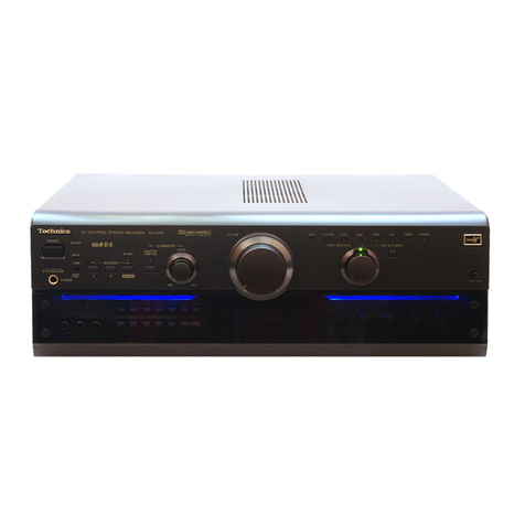
  9. Technics SA-GX230 User manual

Technics SA-GX230 User manual

Other manuals for SA-GX230

1

Other Technics Stereo Receiver manuals

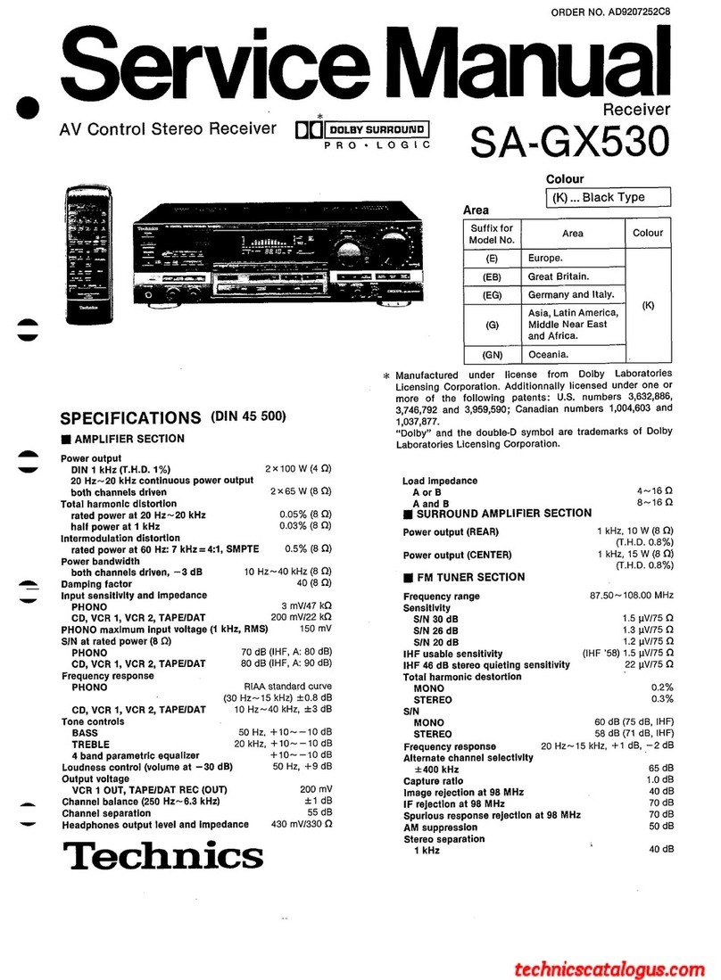
Technics SA-GX550 User manual

Technics

Technics SA-GX550 User manual

Technics SA-AX720 User manual

Technics

Technics SA-AX720 User manual

Technics SA-AX7 User manual

Technics

Technics SA-AX7 User manual

Technics SAEX310 - RECEIVER User manual

Technics

Technics SAEX310 - RECEIVER User manual

Technics SA-AX920 User manual

Technics

Technics SA-AX920 User manual

Technics SADX930 - RECEIVER User manual

Technics

Technics SADX930 - RECEIVER User manual

Technics SA-AX910 User manual

Technics

Technics SA-AX910 User manual

Technics QUARTZ SA-R177 User manual

Technics

Technics QUARTZ SA-R177 User manual

Technics SA-AX730 User manual

Technics

Technics SA-AX730 User manual

Technics SAEX140 - RECEIVER User manual

Technics

Technics SAEX140 - RECEIVER User manual

Technics SA-GX350 User manual

Technics

Technics SA-GX350 User manual

Technics SA-GX130D User manual

Technics

Technics SA-GX130D User manual

Technics SAEX110 - RECEIVER User manual

Technics

Technics SAEX110 - RECEIVER User manual

Technics SAAX6 - RECEIVER User manual

Technics

Technics SAAX6 - RECEIVER User manual

Technics SA-EX510; SA-EX410; SA-EX310 User manual

Technics

Technics SA-EX510; SA-EX410; SA-EX310 User manual

Technics SA-AX540 User manual

Technics

Technics SA-AX540 User manual

Technics SA-AX910 User manual

Technics

Technics SA-AX910 User manual

Technics SA-5250 User manual

Technics

Technics SA-5250 User manual

Technics SA-203 User manual

Technics

Technics SA-203 User manual

Technics SA-5570 User manual

Technics

Technics SA-5570 User manual

Technics RQT5512-Y User manual

Technics

Technics RQT5512-Y User manual

Technics QUARTZ SA-R330 User manual

Technics

Technics QUARTZ SA-R330 User manual

Technics SAAX6 - RECEIVER User manual

Technics

Technics SAAX6 - RECEIVER User manual

Technics SA-DA10 User manual

Technics

Technics SA-DA10 User manual

Popular Stereo Receiver manuals by other brands

Teac AG-680 Service manual

Teac

Teac AG-680 Service manual

Kenwood KR-V888D instruction manual

Kenwood

Kenwood KR-V888D instruction manual

Teac AGV1050 owner's manual

Teac

Teac AGV1050 owner's manual

Sony STR-435 operating instructions

Sony

Sony STR-435 operating instructions

Pioneer Elite SC-68 Service manual

Pioneer

Pioneer Elite SC-68 Service manual

Pioneer SX-1250 operating instructions

Pioneer

Pioneer SX-1250 operating instructions

Marantz CINEMA 70S owner's manual

Marantz

Marantz CINEMA 70S owner's manual

Kenwood KMDX92 instruction manual

Kenwood

Kenwood KMDX92 instruction manual

Yamaha RX-830 owner's manual

Yamaha

Yamaha RX-830 owner's manual

Pioneer AVH-Z7250BT owner's manual

Pioneer

Pioneer AVH-Z7250BT owner's manual

Denon AVR-1311 owner's manual

Denon

Denon AVR-1311 owner's manual

Denon AVR-S760H owner's manual

Denon

Denon AVR-S760H owner's manual

Denon AVR-X7200W Service manual

Denon

Denon AVR-X7200W Service manual

Sony XAV-1500 operating instructions

Sony

Sony XAV-1500 operating instructions

Radio Shack DX-399 owner's manual

Radio Shack

Radio Shack DX-399 owner's manual

Sony STR-DE535 - Fm Stereo/fm-am Receiver operating instructions

Sony

Sony STR-DE535 - Fm Stereo/fm-am Receiver operating instructions

Pioneer SX-1000TA operating instructions

Pioneer

Pioneer SX-1000TA operating instructions

Yamaha MusicCast TSR-5B3D owner's manual

Yamaha

Yamaha MusicCast TSR-5B3D owner's manual

manuals.online logo
manuals.online logoBrands
  • About & Mission
  • Contact us
  • Privacy Policy
  • Terms and Conditions

Copyright 2025 Manuals.Online. All Rights Reserved.

()
AV
Control
Stereo
Receiver
Service
Manual
ORDER
NO.
AD9206177C2
Receiver
SA-GX230
Colour
Area
SPECIFICATIONS
(DIN
45
500)
lI
AMPLIFIER
SECTION
Power
output
DIN
1
kHz
(T.H.D.
1%)
2x80
W
(4 Q)
40
Hz~20
kHz
continuous
power
output
both
channels
driven
2x50
М
(80)
Total
harmonic
distortion.
rated
power
at
40
Hz~20
kHz
-
:
0.5%
(8
О)
half
power
at
1
kHz
Intermodulation
distortion
rated
power
at
60
Hz:
7
kHz—4:1,
SMPTE
Power
bandwidth
both
channels
driven,
—3
dB
0.5%
(8
О)
10
Н2--40
kHz
(8
О)
Damping
factor
40
(8
Q)
Input
sensitivity
and
Impedance
:
PHONO
3
mV/47
КО
CD,
VCR
1
200
mV/22
КО
.
VCR2,
TAPE
.
200
mV/22
kQ
PHONO
maximum
input
voltage
(1
kHz,
AMS):
150
mV
S/N
at
rated
power
(8
©)
.
70
dB
(ІНЕ,
А:
80
dB)
РНОМО
CD,
VCR
1
80
dB
(IHF,
A:90
dB)
VCR
2,
TAPE
80
dB
(IHF,
A:90
dB)
Frequency
response
|
РНОМО
RIAA
standard
curve
|
+0.8
dB
(30
Hz~15
kHz)
CD,
VCR
1
10
Hz~40
kHz
(+3
dB)
VCR
2,
TAPE
10
Hz~40
kHz
(+3
dB)
Tone
controls
|
Bass
.
50
Hz,
+10
dB—
—10
dB
Treble
20
kHz,
+10
dB—
—
10
dB
Loudness
control
(volume
at
—30
dB)
50
Hz,
+9
dB
Output
voltage
VCR
1
OUT
200
mV
TAPE
REC
(OUT)
200
mV
Channel
balance,
250
Hz~6.3
kHz
+1
dB
Channel
separation
-
.
55
dB
Headphones
output
level
and
impedance
430
mV/330
Q
Load
impedance
40-160
80—16
Q
А
ог
В
А
апа
В
Technics
0.03%
(8
Q)
.
Suffix
for
E
ж
(ЕС)
Germany
and
Italy.
(К)
(5)
ll
FM
TUNER
SECTION
Frequency
range
Sensitivity
SIN
30
dB
.1.5
uV
(75
Q)
SIN
26
dB
1.3шУ
(75
О)
SIN
20
ав
_
|
1.2uV
(75
О)
IHF
usable
sensitivity
1.5
uV
(IHF'58,
75
О)
ІНЕ
46
dB
stereo
quieting
sensitivity
.
22
uV/75
О
Total
harmonic
distortion
MONO
.
0.2%
STEREO
|
0.3%
S/N
m
;
cd
MONO
60
dB
(75
dB,
IHF)
STEREO
58
dB
(71
dB,
IHF)
Frequency
response
20
Hz~15
kHz,
+1
dB—
—2
dB
Alternate
channel
selectivity
i
87.50~108.00
MHz
-
+400
kHz
65
dB
-
Capture
ratio
1.0
dB
Image
rejection
at
98
MHz
40
dB
IF
rejection
at
98
MHz
70
dB
Spurious
response
rejection
at
98
MHz
70
dB
AM
suppression
50
dB
Stereo
separation
_1kHz
-—
40
dB
Carrier
leak
19
kHz
—55
dB
(—60
dB,
IHF)
38
kHz
—50
dB
(—55
ав,
ІНЕ)
Channel
balance
(250
Н2--6.3
06
+
1.5
ав
Limiting
point
1.2
uV
Bandwidth
IF
amplifier
180
kHz
FM
demodulator
1000
kHz
Antenna
terminals
75
О
(unbalanced)
SA-GX230
|
ШАМ
TUNER
SECTION
Ш
GENERAL
For
(E/EB)
areas.
Power
consumption
|
|
260
М
Frequency
range
du
4
Power
supply
MW
522
kHz--1611
kHz
(9-kHz
steps)
For
(E,
EB)
areas.
AC
50
Hz/60
Hz,
230
V/240
V
‚
530
kHz—1620
kHz
(10-kHz
steps)
For
(EG)
area.
КЕ
АС
50
Н2/60
Hz,
230
V
LW
144
kHz~288
kHz
Dimensions
(W
x
H
x
D)
430
x
125
x
305
mm
Sensitivity
(S/N
20
dB)
|
Weight
7
kg
MW
бо
20
uV,
330
uV/m
|
LW
45
ыу
Selectivity
(--9
kHz)
:
Ш
REMOTE
CONTROL
TRANSMITTER
MW
(at
999
kHz)
:
55
dB
|
LW
(at
252
kHz)
55
dB
Control
keys
32
keys
Image
rejection
-
Dimensions
(W
x
H
x
D)
70х27х
175
mm
MW
(at
999
kHz)
и.
40
dB
Weight
(including
batteris)
1254
LW
(at
252
kHz)
40
dB
Power
source
Two
UM-4
IF
rejection
|
(Panasonic
ROS/LROS
or
equivalent)
MW
(at
999
kHz)
55
dB
LW
(at
252
kHz)
55
dB
Notes:
For
(EG)
area.
1.
Specifications
are
subject
to
cahnge
without
notice.
Frequency
range
522
КН2--1611
kHz
(9-kHz-Schritte)
|
Weight
and
dimensions
are
approximate.
530
kHz--1620
kHz
(10-kHz-Schritte)
2.
lota!
harmonic
distortion
is
measured
by
the
digital
spectrum
Selectivity
(S/N
20
ав)
|
20
uV,
330
uV/m
analyzer.
ж.
Selectivity
at
999
kHz
-
55
dB
:
Image
rejection
at
999
kHz
40
dB
тш
IF
rejection
at
999
kHz
55
dB
Ш
CONTENTS
Page
Page
АССЕЗЗОШЕЗ
пиков
ыы
бырына
ым»
2
PRINTED
CIRCUIT
ВОАНВВ...........................................
27--32
ВЕРОВЕ
ОЗЕ
—Ó————
2
WIRING
CONNECTION
ШАСВАМ...................................
33
REAR
PANEL
TERMINALS
AND
FUNCTIONS........................
3,4
TERMINAL
GUIDE
OF
IC’S,
TRANSISTORS
AND
DIODES
.....
34
FRONT
PANEL
CONTROLS
AND
FUNCTIONS
......................
5,
6
INTERNAL
CONNECTION
OF
FL
........................---
а.а
35
REMOTE
CONTROL
ОРЕБАТІОЬҺ.......................гг.2л.2.2.444Ү.7Һ/..М..)
7,8
TERMINAL
FUNCTION
OF
IC......................
„нннеее
36
DISASSEMBLY
INSTRUCTIONS
...............................
eese
9~12
CABINET
PARTS
LOCATION
.....c..ccsssssecsessesessrsseserssssseracssosee
37,
38
MEASUREMENTS
AND
ADJUSTMENT
S......................---
13
REPLACEMENT
PARTS
116Т....................2...1...)ц1
(2.2.2.2.
.
39--42
BLOCK
DIAGRAM,
с-сы
рыны
сынын
14--16
RESISTORS
AND
CAPACITORS
........................---
e
eere.
42--44
SCHEMATIC
DIAGRAM,
....................................
1...
а
raura
17--26
PACKAGING
peee-————————————
44
Ш
ACCESSORIES
•
АС
power
supply
cord...
1
pc.
•
ЕМ
indoor
antenna
*
AM
loop
antenna
*
AM
anntena
holder
ene
K
(E,
ES]
(RSA0007)
1
pc.
(SPB1163T)
Я
(SMA231M)
n
—
SJA193
(EB)
==
Au
•
Screws
е
Remote-control
transmitter
е
Batteries
e
Attachment
plug
(XTN3+
10AFZ)
2
pcs.
(RAK-SA302E)
5
(UM-4/RO3)
(SJP9009):
(EB)
only
....
1
pc.
N
for
Remote
control
unit
eS
Ш
BEFORE
USE
|
|
|
=
|
wu
Be
sure
to
disconnect
the
mains
cord
before
adjusting
the
Note
that
this
unit
will
be
seriously
damaged
if
this
setting
is
not
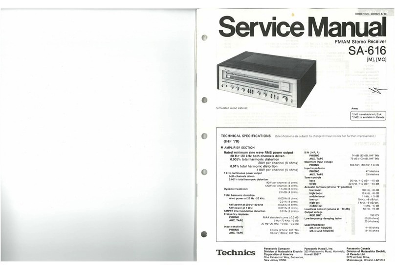
voltage
selector.
made
correctly.
Use
a
flat-tip
(—)
screwdriver
to
set
the
voltage
selector
(on
the
rear
panel)
to
the
voltage
setting
for
the
area
in
which
the
unit
will
be
used.
|
SA-GX230
Ш
REAR
PANEL
TERMINALS
AND
FUNCTIONS
5
Ѕіегео
connection
doble
_
©
“TAPE”
terminals
„^
.
...
Ф
Cooling
fan
(not
included)
Connect
a
tape
deck.
The
cooing
fan
operates
at
i
output
power
levels
only.
Caution:
White
(L)
Do
not
place
books,
etc.,
on
top
of
this
unit
so
that
the
heat
radiation
vents
remain
unblocked.
Red
(R)
бла)
са
.
This
unit
TAPE.
|
ет
PLAY
(IN)
Speaker
connection
terminals
(D(
(AD
Stereo
connection
cables
=
"E
|
(not
included)
` |
|
(9)
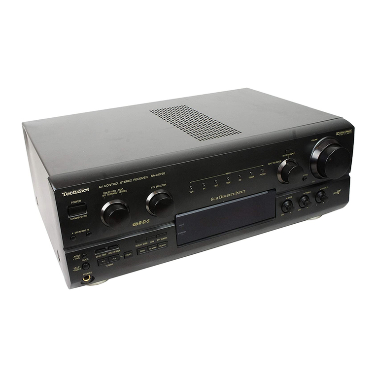
Voltage
selector(VOLT
ADJ):
for
(Е,
EB)
areas
|
~-
Set
the
voltage
selector
to
the
voltage
setting
for
the
area
іп
(R(D
dR
|
which
the
unit
will
be
used.
Tape
deck
|
2
[Use
a
minus
(-)
screwdriver]
(not
included)
3
е
LINE
IN
LINE
OUT
This
unit
©
Remote
control
OUT
terminal
| |
Note:
|
|
| |
l
(REMOTE
CONTROL
OUT)
|
|
Note
that
this
unit
will
be
seriously
d
т .
-
»
| |
у
amaged
if
this
setting
is
not
(D
Antenna
connection
terminals
_
@
“VCR
1"
terminals
.
ща
This
terminal
can
be
used
only
with
Technics
components
made
correctly.
Connect
a
VCR.
А
which
have
the
appropriate
remote
control
terminal.
| ;
(See
the
operating
instructions
of
the
VCR.)
|
(Consult
your
dealer
for
details.)
(2)
“PHONO”
terminals
|
Proper
connection
with
remote
control
connection
cables
Connect
a
йай
odi
Do
not
йе
ыл
This
unit
SJP2257T
will
allow
conirol
of
some
functions
from
this
|
у.
у
|
unit’s
remote
control
transmitter.
(See
pages
7—8
for
“VIDEO
OUT”
terminal
source
to
these
terminals.
ai
:
;
details.)
Connect
a
video
connection
cable
(not
included)
to
the
video
cope
input
terminal
of
the
nem
connected
to
the
"VCR
1”
ter-
@
_
This
unit
mR)
во
Connect
to
a
tape
deck
and/or
compact
disc
player
as
shown
minals.
|
-
||
below.
.
57
When
this
connection
is
made,
tape-to-tape
recording
(audio
|
ыгы
|
|
:
ae
|
and
video)
can
be
carried
out
simply
by
connecting
a
video
Stereo
connection-|.—
,
=
|
If
аре
deck
is
not
being
used,
the
compact
disc
player
сап
camera
or
second
VCR
(for
playback)
to
the
“VCR
2”
ter-
cables
|
|
be
connected
directly
(dotted
line).
|
minals
of
this
unit.
Е
|
p
(not
included)
Stereo
connection
:
Ground
wire
cable
(not
included)
(not
included)
"9D
OR
2%.
T
VCR
This
unit
This
unit
(not
REMOTE
`
|
d
>
a
:
©
-
included)
AUDIO
puno
Ọ
VIDEO
OUT
Connection
cable
for
remote
control
-
(Included
with
tape
‘Video
connection
cable
(not
included)
Turntable
(not
included)
OUTPUTOÓ
©
©
|
Video
connection
-
cable
%
l
4
Ту
(not
included)
Tape
deck
|
(not.
included)
(not
included)
|
@
“CD”
terminals
|
Connect
a
compact
disc
player.
VCR
Connection
cable
|
(not
included)
‚
©
VIDEO
IN
for
remote
control
(Included
with
compact
disc
player)
This
unit
f
i
i
t
t
!
!
1
1
1
I
І
Ц
V
Compact
disc
player
(Т)
ЭК
(not
included)
REMOTE
Stereo
connection
—
cable
(1)
AC
IN
socket
(AC
IN)
(not
included)
Note:
|
Рог
а
compact
disc
player
with
a
remote
control
sensor
the
e
compactat
г
2”
а
4
|
2
24
above
connection
is
not
necessary.
h
player
Í
Е
|
-
2.
|
(not
included)
=
3
“=
=
TM
4
—
|
SA-GX230
SA-GX230
|
|
Ш
FRONT
PANEL
CONTROLS
AND
FUNCTIONS
Tuner
section
(D
(2)
CJARIZ
LOCK
MEMORY
Е
sr
MUTING
cuc
28
1000455
(D
Power
“
©
STANDBYI/ON”
switch
(POWER,
(2
ЗТАМОВУ/ОМ)
This
switch
switches
ON
and
OFF
the
secondary
circuit
power
only.
The
unit
is
in
the
“standby”
condition
when
this
switch
is
set
to
the
Ф
STANDBY
position.
Regardless
of
the
switch
setting,
the
primary
circuit
is
always
“live”
as
long
as
the
power
cord
is
connected
to
an
electrical
outlet.
Remote
control
signal
receptor
(REMOTE
SENSOR)
:
|
Receives
the
signals
from
the
remote
control.
“STANDBY”
indicator
(STANDBY)
This
indicator
illuminates
when
the
"STANDBY"
mode
is
set
by
the
main
unit
or
the
remote
control
transmitter.
Channel
display
This
display
shows
the
channel
number
selected
by
one
of
the
preset-tuning
buttons.
Also
this
display
shows
the
channel
number
for
about
3
seconds
during
memory
scan
operation.
Quartz-lock
indicator
(QUARTZ
LOCK)
This
indicator
illuminates
when
the
unit
is
tuned
precisely
to
a
broadcast
station.
(6
Memory
indicator
(MEMORY)
This
indicator
illuminates
when
the
memory
button
is
press-
ed.
@
FM
stereo
indicator
(FM
ST)
This
indicator
automatically
illuminates
when
an
FM
stereo
broadcast
is
being
received.
Note:
It
will
not
illuminate
if
the
FM
mode
selector
is
set
to
the
monaural
mode.
Memory
scan
indicator
(M.
SCAN)
This
indicator
illuminates
when
the
memory
scan
button
is
pressed.
FM
$400€
N
LOUONESS
BALANCE
AUTO:MONO
«
“он
LEFT
—
AGHT
УСО
—
L
AUDIO
Ч
A—VCA2
\
Ғе
үз
ees
—
|іог
(EG)
area
|
|"
me
|
(8) 16)
а
MERECE
NNUS
4
Band
indicators
(FM,
LW,
MW):
for
(E,
EB)
areas
(FM,
AM)
Indicates
the
selected
band.
:
for
(EG)
area
Input
selector/frequency
display
(INPUT
SELECTOR/FREQUENCY)
Displays
the
selected
source
or
broadcast
frequency.
.
Memory
scan
button
(MEMORY
SCAN)
This
button
is
used
to
locate
a
desired
broadcast
station;
each
broadcast
station
is
selected
for
about
3
seconds.
Tuning
buttons
(TUNING)
These
buttons
are
used
for
tuning
to
the
desired
broadcast
station.
Memory
button
(MEMORY)
This
button
is
used
when
presetting
broadcast
station
fre-
quencies
into
memory.
Preset-tuning
buttons
(1—0)
(30
CHANNEL
RANDOM
PRESET
TUNING)
These
buttons
are
used
to
preset
broadcast
frequencies
into
the
memory
of
this
unit
and
to
recall
the
desired
то
sta-
tions.
Band
selectors
(FM,
LW,
MW):
for
(E,
EB)
areas
(FM,
AM)
:
for
(EG)
area
FM:
Press
this
button
to
listen
to
an
FM
broadcast.
LW:
Press
this
button
to
listen
to
an
LW
broadcast.
MW
(E,
EB)/AM
(EG):
Press
this
button
to
listen
to
an
MW/AM
broadcast.
ALLOCATION:
When
the
MW/AM
button
is
pressed
for
about
3
seconds,
the
MW
frequency
step
will
change
to
10
kHz
per
set.
(This
step
is
set
to
9
kHz
before
shipment.)
In
order
to
return
to
the
original
frequency
indication,
press
this
button
for
about
3
seconds
again.
FM
mode
selector
(FM
MODE)
This
unit
automatically
switches
to
the
stereo
mode
when
an
FM
stereo
broadcast
is
received.
This
selector
is
used
to
select
the
mode
(stereo
or
monaural)
of
FM
broadcast
signals.
----
3
Amplifier
section
.
for
(EG)
area
(D
Speaker
selectors
(SPEAKERS)
These
selectors
are
used
to
select
the
speaker
system(s)
(A
and/or
B).
Muting
indicator
(MUTING)
This
indicator
will
illuminate
when
the
muting
button
(on
the
remote
control
transmitter)
is
pressed.
Loudness
indicator
(LOUDNESS)
This
indicator
will
illuminate
when
the
loudness
button
is
pressed.
@
Tape
indicator
(
)
This
indicator
will
illuminate
when
the
tape-monitor
button
is
pressed.
:
|
©
Volume
control
(VOLUME)
Tone
controls
(BASS,
TREBLE)
The
bass
control
is
used
to
adjust
the
low-frequency
sound
range,
and
the
treble
control
is
used
to
adjust
the
high-fre-
quency
sound
range.
(D
Headphones
jack
(PHONES)
Input
selector
buttons
These
buttons
are
used
to
select
the
sound
source
to
be
heard,
such
as
a
disc,
radio
broadcasts,
etc.
The
selected
sound
source
is
shown
on
the
input
selector/frequency
display.
The
“PHONO”
input
selector
has
two
functions:
when
press-
ed
momentarily
it
selects
“PHONO”.
When
pressed
and
held
for
about
4
seconds,
it
de-activates
the
muting
function.
=
TONE
CONTROL.
TREBLE
loo
(9
Tape-monitor
button
(TAPE
MONITOR)
Press
this
button
to
listen
to
a
tape.
To
listen
to
some
other
source,
press
this
button
once
again
(so
that
the
indicator
is
switched
OFF).
Loudness
button
(LOUDNESS)
Set
to
the
“ON”
position
(the
loudness
indicator
will
il-
luminate);
when
listening
to
music
at
low
volume.
Auditory
perception
of
sound
in
the
low
frequency
range
falls
off
at
low
volume,
but
when
the
switch
is
in
this
position,
this
defi-
ciency
is
compensated
for,
so
that
the
full
impact
of
tha
musical
performance
can
be
enjoyed.
й)
Balance
control
(BALANCE)
(2
“VCR
2”
terminals
(VCR
2)
These
terminals
are
used
for
tape-to-
-tape
recording
if
a
se-
cond
VCR
is
connected
here.
Ш
REMOTE
CONTROL
OPERATION
*
This
remote
control
transmitter
can
be
used
for
control
of
a
Technics
cassette
tape
deck
or
a
compact
disc
player
with
a
remote
control
terminal.
Consult
your
dealer
for
details.
e
For
detailed
information
concerning
operation
steps,
etc.,
please
refer
to
the
appropriate
page
for
each
unit
and
the
respective
operating
instructions.
®
For
this
system,
you
can
listen
to
tapes
or
compact
discs,
etc.,
by
operating
the
remote
control
transmitter
without
using
this
unit's
input
selectors.
-
*
Make
sure
that
the
power
of
each
unit
is
set
to
the
"ON"
posi-
tion,
before
beginning
the
operations.
.
Facing
toward
the
main
unit
TUNER
CD
Bias
E
1
5
ЕСЕН
с»
BE
REMOTE
CONTROL
TRANSMITTER
AUDIO
RAK-SA302E
Technics
|
SA-GX230
[A][Tunercontrols
^
^
^
1—
|
Press
this
button
first
to
use
the
"OFF/ON"
button
or
the
[1]
—
[o]
buttons.
This
button
can
be
used
for
ON
and
OFF
switching
of
this
unit.
When
switching
the
power
ON
and
OFF,
be
sure
to
first
press
the
“TUNER”
button.
[1]
—
[0]
Press
these
buttons
to
select
the
desired
preset
channel.
When
these
buttons
are
used,
be
sure
to
first
press
the
"TUNER"
button.
To
designate
channels
1—9:
Press
the
appropriate
(1—9)
preset-tuning
button.
Note:
When
selecting
channel
1,
2
or
3
enter
the
selection
"O1",
“02”
or
“03”.
If
only
“1”,
"2"
or
"3"
is
pressed,
channel
access
will
be
delayed
by
two
seconds.
To
designate
channels
10—30:
(D
Press
the
button
for
the
“tens”
digit
(1,
2
or
3).
@
Press
the
button
for
the
"units"
digit
(1-0)
within
2
seconds
after
pressing
the
first
button.
Note:
If
the
interval
between
pressing
the
first
button
and
pressing
the
second
button
is
more
than
about
2
seconds,
the
setting
may
not
be
made
correctly.
n
this
Шы
make
the
setting
once
again.
[B]
[Tape
deck
controls
(
Tape
deck
controls
|
Press
this
button
to
select
the
deck
("DECK
1”
or
"DECK
2")
to
be
controlled.
Press
this
button
to
change
to
the
recording
stand-by
mode.
[<<], [>>].
Press
one
of
these
buttons
to.
advance.
or
rewind
the
tape
while
the
unit
is
in
the
stop
mode.
Press
one
of
these
buttons
to
select
the
desired
tune
while
the
unit
is
in
the
play
mode.
(Only
applicable
to
a
Technics
tape
deck
with
the
“music
select”
functions.)
Press
this
button
to
temporarily
stop
playback
or
recording.
Press
the
playback
button
to
resume
the
playback
or
recording.
Press
one
of
these
buttons
to
begin
playback
or
recording,
press-
ing
the
button
corresponding
to
the
side
of
the
tape
to
be
played
back
(or
recorded).
>
:
For
the
“forward
(А)"
side
of
the
tape
«4
:
For
the
“reverse
(В)”
side
of
the
tape
Note:
Depending
on
which
Technics
tape
deck
is
used
in
combination
with
this
unit,
tape
deck
1
might
be
the
"A"-side
playback-only
type.
Press
this
button
to
stop
tape
movement.
Note
Depending
on
which
Technics
tape
deck
is
used
in
combina-
tion
with
this
unit,
the
pause
of
the
playback
(and
the
recor-
ding),
and
the
recording
functions
of
tape
deck
1
might
not
be
possible
by
using
the
remote
control
transmitter.
SA-GX230
|
Compact
disc
player
controls
Press
this
button
first
to
use
the
[1]
—
buttons.
=
|
Press
these
buttons
to
select
the
desired
track.
Playback
begins
from
the
track
selected.
When
these
buttons
are
used,
be
sure
to
first
press
the
"CD"
but-
ton.
Tracks
1—9:
Press
the
appropriate
numeric
button
с
E
à
directly.
To
select
a
two-digit
track
number
over
10:
Press
the
c3
button
the
necessary
number
of
time
to
select
the
"tens"
digit,
and
then
one
of
the
©
—
c
buttons
to
select
the
"units"
digit.
E
If
a
Technics
multi
compact
disc
player
is
used
in
combination
with
this
unit,
the
disc
to
be
played
can
be
selected
by
first
press-
ing
this
button
and
then
pressing
the
appropriate
numeric
button
ТҮРЕН
Press
this
button
to
select
the
desired
play
made.
(“РВООНАМ”
or
"CONTINUE")
Press
one
of
these
buttons
briefly
to
move
the
pick-up
to
the
-—
Е
beginning
of
а
specific
track.
TUNER
.
|
co
2
os
EZ] СС)
[>
PLAY]
2
3
5
Facing
toward
the
main
unit
Dv
:
ress
this
button
to
start
play.
Press
this
button
to
stop
play.
PROGRAM
MODE
Note:
ею
C2
E
When
operating
a
compact
disc
player
with
a
remote
control
sen-
sor,
face
this
remote
contro!
transmitter
toward
the
remote
con-
trol
sensor
of
the
compact
disc
player.
заь.
:
REMOTE
CONTROL
TRANSMITTER
AUDIO
RAK-SA302E
Technics
[р]
Amplifier
controls
Press
this
button
to
select
the
“VCR
1”
input
selector
on
the
main
unit.
Press
this
button
to
temporarily
reduce
the
volume
level.
—
The
volume
level
is
attenuated
by
20
dB
(approx.
1/10).
TE
Press
once
again
to
return
to
the
previous
volume
level.
Press
one
of
these
buttons
to
adjust
the
volume
level.
—
8
—
|
SA-GX230
Ш
DISASSEMBLY
INSTRUCTIONS
“ATTENTION
SERVICER”
|
e
Some
chassis
components
may
have
sharp
edges.
Ве
careful
when
disassembling
and
servicing.
|
|
ҚАЙ
Removal
of
the
cabinet
Neat
Removal
of
the
front
panel
ass’y
Procedure
|
[m]
1.
Remove
the
2
flat
cables
(CN401,
CN601).-
Front
panel
ass’y
Speaker
switch
/
Headphones
jack
B
2.
Remove
the
3
screws
(0
—
9).
3.
Remove
the
front
panel
ass'y
in
the
direction
of
arrow.
:
How
to
remove
the
flat
cable
1.
Lift
up
the
connector.
2.
Pull
out
the
flat
cable.
Flat
cable
|
E
Connector
[А
-
Procedure
1524
Tone
control
knobs
Balance
knob
1.
Remove
the
2
tone
control
knobs
and
a
balance
2.
Remove
the
5
screws
(Q
—
©).
knob.
|
SA-GX230
|
ЖЕЕ
Removal
of
the
volume
P.C.B.
27
Removal
of
the
FL
drive
P.C.B.
Procedure
Volume
knob
Procedure
|
12525
15256
e
FL
Drive
PC.B.
.
Pull
out
the
volume
knob.
.
Remove
the
nut.
.
Remove
the
1
screw
(@).
1.
Remove
the
5
screws
(Q
—
©).
.
Remove
the
volume
P.C.B.
in
the
direction
of
arrow.
2.
Remove
the
FL
drive
P.C.B.
in
the
direction
of
arrow.
P
m
Ref.
No.
Removal
of
the
power
switch
P.C.B.
Ref.
No.
wW
and
Operation
P.C.B.
Removal
of
the
VCR2
P.C.B.
Procedure
Procedure
12256
|
1228
Power
switch
P
C.B.
|
е
Remove
the
13
screws
(@
—
Ф).
е
Remove
the
2
screws
(@,
Ө).
|
эчи
T
Removal
of
the
rear
panel
i
ou
Removal
of
the
tuner
P.C.B.
Procedure
Procedure
1-9
Rear
panel
19-10
1.
Remove
the
13
screws
(Q
—
Ф).
2.
Remove
the
1
connector
(CN651).
1.
Release
the
1
claw.
3.
Remove
the
rear
panel
ín
the
direction
of
arrow.
2.
Remove
the
tuner
P.C.B.
in
the
direction
of
arrow.
SA-GX230-
Ш
MEASUREMENTS
AND
ADJUSTMENTS
Note:
For
2201/2251
(AM
(MW/LW)
ANT
and
OSC
coil),
7202
(AM
(MWILWMIFT),
they
are
supplied
as
adjusted
parts.
|
So,
do
not
turn
the
cores
of
the
parts.
Н
is
not
necessary
to
adjust
the
AM
(MW/LW)
circuit.
*
FM
ADJUSTMENT
Control
positions
and
equipment
used
*
FM
signal
generator
(FM-SG).
*
Frequency
counter
*
Distortion
analyser
•
Choke
coil
(100pH)
*
DC
electronic
voltmeter
(DC
EVM)
*
Resistor
(100
kQ)
.
Remove
the
motor
cover
by
used
©
screwdriver.
(Refer
to
Fig.
3)
4.
Remove
the
motor
from,
the
fancasing.
Ref.
No.
Removal
of
the
power
supply
P.C.B.
ner
NO;
Removal
of
the
power
transformer
ner
No:
Removal
of
the
cooling
fan
motor
11
12
(main)
16
Procedure
Procedure
Procedure
o
12911
1911412
1->9->16
(Refer
to
Fig.
4)
5.
When
mounting
the
motor
fan,
align
the
fan
1.
Release
the
3
claws
in
the
direction
of
arrow
and
casing’s
projection
with
the
hole
of.the
fan
motor.
remove
the fan
motor.
(Refer
to
Fig.
1)
|
2.
Insert
a
screwdriver
at
the
root
of
the
cooling
fan.
Force
it
out
of
the
motor
shaft.
(Refer
to
Fig.
2)
transformer
Cooling"
fari
(main)
FM
MONO
DISTORTION
ADJUSTMENT
FM
SIGNAL
GENERATOR
CONDITION
.
Test
equipment
connection
is
shown
in
figure.
Modulation
.
Set
the
unit
to
“FM”
position.
.
Set
the
radio
frequency
display
and
signal
generator
to
100.10
MHz.
|
|
|
о
T
.
Adjust
Т201
core
so
that
voltage
measured
in
signal
mode
is
OmV
(0+20mV)
in
300mV
range.
.
Adjust
T202
so
that
the
distortion
factor
of
Lch
is
minimized.
.
.
EM
ET
.
Repeat
step
4
and
5a
few
times.
—
.
Make
sure
that
the
distortion
factors
of
Lch
and
Rch
are
nearly
the
same
with
each
other
to
minimum.
Power,
supply
PC.
B.
1.
Remove
the
1
screw
(@).
|
2.
Remove
the
1
flat
cable
(CN702).
3,
Remove
the
power
supply
P.C.B.
in
the
direction
of
arrow.
2
Ұй
|
Қай
Removal
of
the
regulator
transistor
|
Procedure
1-2-13
Remove
the
2
screws
(Ф,
Ө).
Remove
the
2
transistor
holders.
Lift
up
the
connector
in
the
direction
of
arrow
(D.
Remove
the
regulator
transistor
in
the
direction
of
arrow
©).
Note:
Ref
№.
|
Check
of
the
main
P.C.B.
Procedure
|
swhen
checking
the
soldered
sur-
1—17
faces
of
main
P.C.B.
and
replacing
—
.
о
o
the
parts,
do
as
show.
X
f
Front
panei
аѕѕ?у
The
adjusting
screwdriver
used.
should
be
made
of
resin.
|
|
|
емей
ай
=
FM
MPX
VCO
ADJUSTMENT
FM
SIGNAL
GENERATOR
CONDITION
.
Test
equipment
connection
is
shown
in
figure.
Modulation
.
Set
the
unit
to
"FM
auto"
position.
|
.
Set
the
radio
frequency
display
and
signal
generator
ÉREGUENEY
to
100.10
MHz.
QU
ENNA
COUNTER
.
Adjust
VR301
for
19.00+0.03kHz
on
frequency
counter
reading.
—
.
> 3 i
па
й
зі
:
|
X
USING
ALTERNATE
SYSTEM
1.
Apply
stereo
signa!
from
generator
or
receive
the
stereo
broadcast.
|
2.
Adjust
VR301
until
stereo
indicator
lights
up.
%
-
®
—
©
:
Stereo
OFF
Cement
arm
of
VR301
as
shown
in
figure.
*
When
mounting
the
regulator
transistor.
Apply
silicone
thermal
compound
(RFKX0002
or
equivalent)
to
the
rear
of
the
regulator
transistor.
Removal
of
the
main
P.C.B.
LET
Removal
of
the
power
IC
|
Procedure
Procedure
125259
152—910
position
-
©
:
Stereo
ON
positlon
|
(indicator
lighting)
|
©:
Adjust
point
of
Pilot
circult
1.
Remove
the
3
screws
(Ф--Ө).
Rear
panel
*
Adjustment
points
a.
а
Please
refer
to
tuner
P.C.B.
on
pages
27,
28.
TH
Teel
a
UEM
SD
SM
GNO
E
44%
Y
—
[——
750.
Unsolder
the
power
IC
FM
ANT
?
"
‚
1.
Remove
the
2
screws
(Ф,
Ө):
|
@
‚2.
Unsolder
the
power
IC.
BALANCED
TUNER
P.C.B.
Front
panel
ass!y
¢
When
mounting
the
power
IC.
1.
Remove
the
1
flat
cable
(CN702).
^A
Apply
silicone
thermal
compound
.
(RFKX0002
ог
2.
Remove
the
6
screws
(Q
—
OQ).
|
equivalent)
to
the
rear
of
the
power
IC.
3.
Remove
the
6
screws
(D—().
—
5.
Remove
the'chassis
ass’y.
4.
Remove
the
rear
panel
іп
the
direction
of
arrow..
6.
Reinstall
the
front
panel ass’y
to
the
main
P.C.B.
FM
offset!
FM
МОНО
coll
OISTORTION
сон
—Hh-
|
—12—
|
ue
n
—
13—
[129]
[1202]
d
|
|
|
‚
|
T
|
i
'
|
|
!
|
|
SA-GX230
SA-GX230
|
SA-GX230
B
BLOCK
DIAGRAM
|
|
AM6558F
FM
MONO
DISTORTION
ад]
D
D
TP201
TP202/
ra0),200
sl
PHONO
EQUALIZER
AMP
Jj
Js
TC9163N
SA
ESIN
C]
Г]
T°
F
ТЕ
301
R314,
:
—
Qe
a—
na
(C
жекен
401
a
b
E
ji
SD
|
ЕМ
MPX
ыы
ЕШ
Г
1
ECTOR
Ex
FM
FRONT
END
серді
CF202
148
э
Де
МӨ
Ue
|4
_____
ANT2T3A
|
|
INPUT
SEL
MOTOR
DRIVE
(VOLUME)
ae
er
|
r^
Ф
(2
heel
wel
Vcc
71
ІС201
г----
—
е
нь
ама
найи
Ў
m
25:
а
—
237
|
ЯҒ
Атр.
FM
iF
АМР
1
|
AM/FM
IF
А
:
ед
"m
|
|
|
ТІК
Шың
?
=
|
AMP,DET
&
AM
MIXER
Бе
—————
cre
Ж.
Fe
|
1-52
|
|
E
|
|
со.
|
ger
enoNo
:(Q
SEA
|
8)
—ү
|
E
02019202
:
|
4
|
|
!
2,5,8
i
7202
|
oS
T8
!
езе
Hore
|
О]
|
L
3,4
BUFFER
CO
(№
al
г--і-4
126)
x2
|
Lh
O
—
=
—
(5
(2 (a
Ф,
|
|
'
ою,
|.
|
fone
4
YOLUME
GD
aoe
=
|
FORCIBLE
22
pr
|
—
|
MOTOR
|
FM
FM/AM
LOOP
>
моно/
_
;
|
FILTER
¥CO
STOP
ср
5
|
|
|
nog
р
:
ea
|
|
BUFFER
AMP
|
|
MUTING
---
А
: ;
.
; |
г
|
УРСа5ТОС
MC
|
:
к
x4
|
|
co
69
|
|
|
1CA71
AM
ANT.
|
г
Г
REC(OUT)
{С
—‘о
|
|
Sc
T
!
|
EZ
we
`
'
ч
5—0
TONE
CONTROL
a
|
ТАРЕ
|
—
[
E
|
|
=
22011601
i
7
r
і
9 5
E
Св)
zai
|,
Z25I:1£,EB
Б
PLATO
>
i221)
d
t20)
эң
1,
)
ЕС
А
АМ
ANT.
COIL
TP301
|
4
j
6l
ES
[
VRBO!
Pa
Г
ens
<
ҮН50І
МЕХ.
УСО
adJ.
8
Жо
куры
VOLUME
АМ
A
l
056.
COIL
Т
mex
veo
aa),
213
xe
|
|
|
0501,502
on
aed
|
OUT
С
рү?
те
|
1...
5|
ч
Г
im
1
|
Ы
SWITCHING
:
134
P
1 ]
ҮСЕ!
5%
ema
BY
(LOUONESS)
асы
6
(9
|
Г
|
3
|
т
e
ү
|
5255256
i
L
|
д8
xe
[
|
1
l
›
0210
92050206
UN
€
io
p
3-4
|
|
Qst
|
|
AM(Mw/LWI
|
AM
UMW/LW)
SIGNAL
us)
T
|
m
ias
|
|
LOOP
FILTER
Q251--254
т
40101
1
OSC
BUFFER
DET.
|
vR502
ATTENUATOR
AMAMW/LW)
|
rene,
в
BALANCE
vR471,472
B.
DRIVE
IM
VCR2
"VIDEO
IN
|
ы
owas)
|
|
|
|
|
b
0814,
615
0505,
| з
0506
|
5
Q103,104
VIDEO
OuT
FT
in
SWITCHING
A
,
E
RR
ULP
ANT
a,
1
Н
Г
хот
XIN
РО!
FH
IN
BOT
1
с
L
10
|
мен
ERE
ЗЕ
|
b
|
мроі
voo?
се
Ск
DATA
A
—
OS
ee
—
ініні.
—
——
a
.—
—
шч
ық
үші
ш=ч
(Ср
=
=”
—
—
I6
3
4
5
1.47001
iB
PLL
FREQUENCY
|
о
=
з.
SV13205B
POWER
AMP
Ба
HEADPHONES
i
!
І
13
(30
[32
|
ж
CE
СКІ
OATAl
ҒЫ
FMSY
IEY
AFM
-20dB
F
R
iš
MONO
tiov)
oc
m
eerte
D701^,
704
RECITIFIER
Q701,703,
704,713
a
Q705
45
(+8)
ММ1871255ТУ
|
8
.
|
|
ТЕ
Yep
HD
^
0709,710
40
MICROCOMPUTER
|
ORFA
REGULATOR
1
17
26,35,37
55D
.
!
|
,
1
bs
FL
DISPLAY
|
|
d
e
RN
Q901,902
|
REMOTE
0н
KEY
MATRIX
SPEAKERS
(E,
EB)
only
|
'
.
К
0554
|
a
pe
|
b
——
—
(“мі
тын»
oe
Q
е
|
отоу
754
р
ака
ооо
4
16
|)
^s
1
RECITIFIER
S
SERVICE
|
с
|
У$Б
$
+
INTERRUPTION
Ó
RESET
FAN
MOTOR
065.655
р
G8)
0501
:
RL
ёо!
DETECTOR
i
MOTOR
|
быз
reu
_________
тм
рото
v
oer
so
ses
|
(М)
c
mee
|
Г
27
54
46
535
зал
$9^,64
.
Note:
аа
жегі
ЕМ
(AF)
signal
«гипс»
FM
OSC
signal
REMOTE
г-------
REMOTE
CONTROL
ц
,
*u—
AM
(MW/LW)
signal
eo
dedu
=
шіні
•
тиниў
AM
(MW/LW)
OSC
signal
c
Phono
signal
A
8
[
FL
DISPLAY
|
г
'
|
|
*(
)
indícates
Pin
No.
of
right
channel.
TRANSFORMER
|
|
;
.
2