TechnipFMC Proline Promass 500 User manual

SD01918O/06/EN/02.17
Valid as of version 01.01.zz (Device rmware)
71382450
Web Server Manual
MANUAL
Special Documentation
Proline Promass 500
Modbus RS485

Important
All information and technical specications in this documentation have been carefully checked and compiled by
the author. However, we cannot completely exclude the possibility of errors. TechnipFMC is always grateful to be
informed of any errors. Contact us on the website.
Smith Meter® is a registered trademark of TechnipFMC.
Technical Support
Contact Information:
Field Service Response Center
24/7 Technical Support/Schedule a Technician: 1-844-798-3819
System Installation Supervision, Start-Up, and Commissioning Services Available
Customer Support
Contact Information:
Customer Service
TechnipFMC
1602 Wagner Avenue
Erie, Pennsylvania 16510 USA
P: +1 814 898-5000
F: +1 814 899-8927
measurement.solutions@TechnipFMC.com
TechnipFMC.com
Literature Library:
http://fmctechnologies.com/en/MeasurementSolutions/OnlineServices.aspx

Proline Promass 500 Modbus RS485 Table of contents
3
Table of contents
1 About this document ................ 4
1.1 Document function ..................... 4
1.2 Target group .......................... 4
1.3 Using this document .................... 4
1.4 Symbols used .......................... 5
2 Basic safety instructions ............ 6
2.1 Requirements for personnel ............... 6
2.2 Designated use ........................ 6
2.3 Occupational safety ..................... 6
2.4 Operational safety ...................... 6
2.5 Product safety ......................... 6
2.6 IT security ............................ 7
2.7 Device-specific IT security ................. 7
3 Product features and availability ..... 8
3.1 Product features ....................... 8
3.2 Availability ........................... 8
3.3 Identification in the measuring device ....... 8
4 Commissioning .................... 10
4.1 Prerequisites - computer ................ 10
4.2 Prerequisites - measuring device .......... 16
4.3 Connecting the computer to the measuring
device .............................. 16
4.4 Establishing a connection to the Web
server .............................. 18
4.5 Setting the IP address .................. 20
4.6 Overview of the Web server parameters ..... 20
5 Operation options ................. 23
5.1 Logging on .......................... 24
5.2 User interface ........................ 25
5.3 Logging out .......................... 26
6 Diagnostics and troubleshooting ... 27
6.1 General Web server troubleshooting ........ 27
6.2 Diagnostic information in the Web browser .. 28
6.3 Diagnostic information in the measuring
device .............................. 29
6.4 Checking the network connection .......... 29
7 Technical data .................... 31

About this document Proline Promass 500 Modbus RS485
4
1 About this document
1.1 Document function
This manual is a Special Documentation; it does not replace the Operating Instructions
pertaining to the device. It serves as a reference for using the Web server integrated in the
measuring device.
1.2 Target group
The document is aimed at specialists who work with the device over the entire life cycle
and perform specific configurations.
1.3 Using this document
1.3.1 Information on the document structure
This Special Documentation contains a range of information, including:
• Prerequisites for use on the computer and measuring device
• Connection of the computer via the service interface or WLAN interface
• Configuration of the communication interface
• Establishing a connection
• Diagnostics and troubleshooting
The information and safety instructions in the Operating Instructions pertaining to
the measuring device must always be observed → 4.
1.3.2 Device documentation
The Technical Documentation for the measuring device is available:
• On the CD-ROM supplied with the measuring device (depending on the device version,
the CD-ROM might not be part of the delivery!)
• Via the W@M Device Viewer: enter the serial number from the nameplate
(www.endress.com/deviceviewer)
• Via the Endress+Hauser Operations App: enter the serial number from the nameplate or
scan the 2-D matrix code (QR code) on the nameplate.
Technical documentation can also be downloaded from the Download Area of the
Endress+Hauser web site: www.endress.com → Download. However this technical
documentation applies to a particular instrument family and is not assigned to a
specific measuring device.

Proline Promass 500 Modbus RS485 About this document
5
1.4 Symbols used
1.4.1 Safety symbols
Symbol Meaning
DANGER
DANGER!
This symbol alerts you to a dangerous situation. Failure to avoid this situation will
result in serious or fatal injury.
WARNING
WARNING!
This symbol alerts you to a dangerous situation. Failure to avoid this situation can
result in serious or fatal injury.
CAUTION
CAUTION!
This symbol alerts you to a dangerous situation. Failure to avoid this situation can
result in minor or medium injury.
NOTICE
NOTE!
This symbol contains information on procedures and other facts which do not result in
personal injury.
1.4.2 Symbols for certain types of information
Symbol Meaning
Permitted
Indicates procedures, processes or actions that are allowed.
Forbidden
Indicates procedures, processes or actions that are forbidden.
Tip
Indicates additional information.
Reference to documentation
A
Reference to page
Reference to graphic
Notice or individual step to be observed
1.
,
2.
,
3.
… Series of steps
Result of a step
1.4.3 Symbols in graphics
Symbol Meaning
1, 2, 3,... Item numbers
1.
,
2.
,
3.
… Series of steps

Basic safety instructions Proline Promass 500 Modbus RS485
6
2 Basic safety instructions
2.1 Requirements for personnel
Personnel involved in installation, commissioning, diagnostics and maintenance must
meet the following requirements:
‣Trained, qualified specialists must have a relevant qualification for this specific function
and task
‣Are authorized by the plant owner/operator
‣Are familiar with federal/national regulations
‣Before starting work, read and understand the instructions in the manual and
supplementary documentation as well as the certificates (depending on the
application)
‣Follow instructions and comply with basic conditions
Operating personnel must meet the following requirements:
‣Be instructed and authorized by the plant operator with regard to the requirements of
the task
‣Follow the instructions in this manual
2.2 Designated use
The designated use of the measuring device is described in the Operating Instructions
pertaining to the device → 4.
2.3 Occupational safety
For work on and with the device:
‣Wear the required personal protective equipment according to federal/national
regulations.
If working on and with the device with wet hands:
‣It is recommended to wear gloves on account of the higher risk of electric shock.
2.4 Operational safety
Risk of injury!
‣Operate the device in proper technical condition and fail-safe condition only.
‣The operator is responsible for interference-free operation of the device.
Modifications to the device
Unauthorized modifications to the device are not permitted and can lead to unforeseeable
dangers.
‣If, despite this, modifications are required, consult with Endress+Hauser.
2.5 Product safety
This device is designed in accordance with good engineering practice to meet state-of-the-
art safety requirements, has been tested, and left the factory in a condition in which it is
safe to operate.

Proline Promass 500 Modbus RS485 Basic safety instructions
7
It meets general safety standards and legal requirements. It also complies with the EC
directives listed in the device-specific EC Declaration of Conformity. Endress+Hauser
confirms this by affixing the CE mark to the device.
2.6 IT security
We only provide a warranty if the device is installed and used as described in the
Operating Instructions. The device is equipped with security mechanisms to protect it
against any inadvertent changes to the device settings.
IT security measures in line with operators' security standards and designed to provide
additional protection for the device and device data transfer must be implemented by the
operators themselves.
2.7 Device-specific IT security
The device offers a range of specific functions to support protective measures on the
operator's side. These functions can be configured by the user and guarantee greater in-
operation safety if used correctly.
2.7.1 Access via CDI-RJ45 service interface
The device can be connected to a network via the CDI-RJ45 service interface. Device-
specific functions guarantee the secure operation of the device in a network.
It is advisable to take relevant security concepts into consideration, such as those issued by
the Federal Office for Information Security. This includes organizational security measures
such as the assignment of access authorization as well as technical measures such as
network segmentation.
Product features and availability Proline Promass 500 Modbus RS485
8
3 Product features and availability
3.1 Product features
Thanks to the integrated Web server, the device can be operated and configured via a Web
browser and via a service interface (CDI-RJ45) or via a WLAN interface. The structure of
the operating menu is the same as for the local display. In addition to the measured values,
status information on the device is also displayed and allows the user to monitor the status
of the device. Furthermore the device data can be managed and the network parameters
can be configured.
A device that has a WLAN interface (can be ordered as an option) is required for the
WLAN connection: order code for "Display; operation", option G "4-line, illuminated; touch
control + WLAN". The device acts as an Access Point and enables communication by
computer or a mobile handheld terminal.
3.2 Availability
The integrated Web server is a standard feature. It does not need to be ordered for the
device ex works as it is provided as standard when the device is delivered to the customer.
No particular measures are required to put the feature into operation.
3.3 Identification in the measuring device
An adhesive label on the inside of the electronics compartment cover or the connection
compartment describes all the available hardware components, and their functions, for the
measuring device. The service interface (CDI-RJ45) has the following identification:
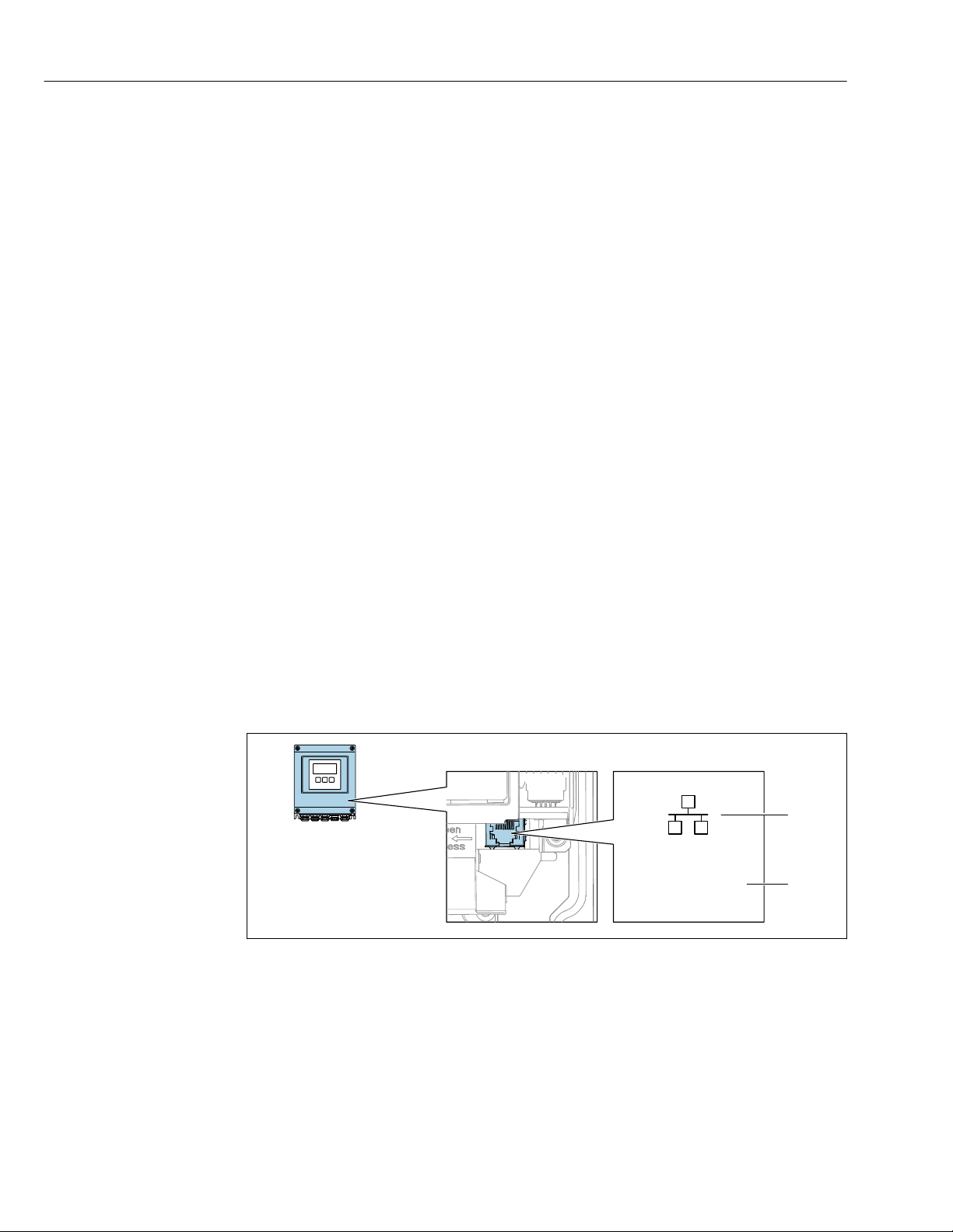
3.3.1 Proline 500 – digital
Service Int. (CDI)
IP 192.168.1.212
1
2
A0031138
1 Example of the CDI-RJ45 service interface
1 Symbol for service interface
2 Information on the default setting for the WLAN IP address
Proline Promass 500 Modbus RS485 Product features and availability
9
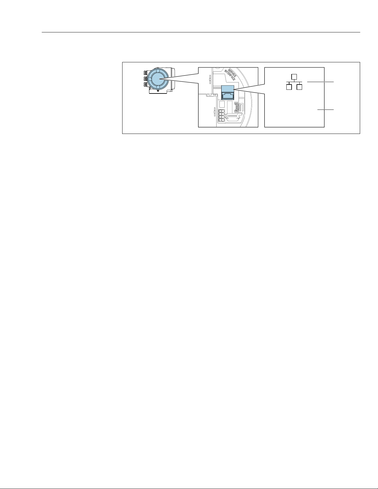
3.3.2 Proline 500
Service Int. (CDI)
IP 192.168.1.212
1
2
A0030874
2 Example of the CDI-RJ45 service interface
1 Symbol for service interface
2 Information on the default setting for the WLAN IP address
Commissioning Proline Promass 500 Modbus RS485
10
4 Commissioning
Establishing a connection to the integrated Web server
1. Configure the computer → 10.
2. Check the settings on the measuring device and change them if necessary → 16.
3. Connect the measuring device to the computer → 16.
4. Establish a connection to the Web server → 18.
5. Start the Web browser and access the operating menu → 19.
The measuring device can be operated via the Web server.
4.1 Prerequisites - computer
4.1.1 Hardware
Hardware Interface
CDI-RJ45 WLAN
Interface The computer must have an RJ45
interface.
The operating unit must have a
WLAN interface.
Connection Standard Ethernet cable with RJ45
connector.
Connection via Wireless LAN.
Screen Recommended size: ≥12" (depends on the screen resolution)
4.1.2 Software
Software Interface
CDI-RJ45 WLAN
Recommended operating
systems
• Microsoft Windows 7 or higher.
• Mobile operating systems:
– iOS
– Android
Microsoft Windows XP is supported.
Web browsers supported • Microsoft Internet Explorer 8 or higher
• Microsoft Edge
• Mozilla Firefox
• Google Chrome
• Safari
4.1.3 Configuring the computer
User rights Appropriate user rights (e.g. administrator rights) for TCP/IP and proxy server
settings are necessary (for adjusting the IP address, subnet mask etc.).
Proxy server settings of the
Web browser
The Web browser setting Use a Proxy Server for Your LAN must be
deselected .

Proline Promass 500 Modbus RS485 Commissioning
11
JavaScript JavaScript must be enabled.
If JavaScript cannot be enabled:
enter http://192.168.1.212/basic.html in the address line of the Web
browser. A fully functional but simplified version of the operating menu
structure starts in the Web browser.
When installing a new firmware version: To enable correct data display,
clear the temporary memory (cache) of the Web browser under Internet
options.
Network connections Only the active network connections to the measuring device should be used.
Switch off all other network connections such as WLAN.

Commissioning Proline Promass 500 Modbus RS485
12
Configuring IP settings for Windows
• To configure the IP settings, appropriate user rights (e.g. administrator rights) are
required for the computer.
• Before configuring the IP settings, close all the windows of the Web browser.
1. Click Start (Windows icon).
The Start menu appears.
2. In the Start menu, select Control Panel.
This opens a new window with the control panel elements.
adapter
A0024277
3. Enter the term "adapter" in the search field.
The Network and Sharing Center is listed in the search results.
4. Select the Network Connections option under Network and Sharing Center.
This opens a new window with the network connections.
A0024293
5. In this window, select the Local Area Connection (LAN).
Proline Promass 500 Modbus RS485 Commissioning
13
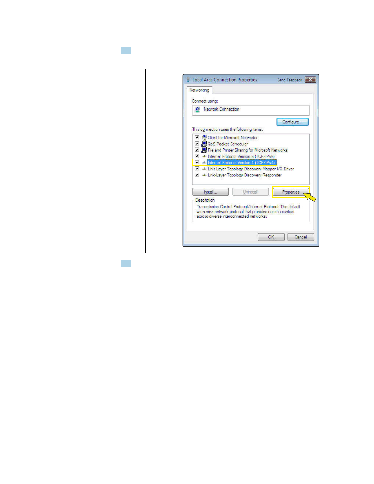
6. Right-click to open the picklist and select Properties.
The Local Area Connection Properties dialog box opens.
A0024300
7. Select the Internet Protocol Version 4 (TCP/IPv4) item.
Commissioning Proline Promass 500 Modbus RS485
14
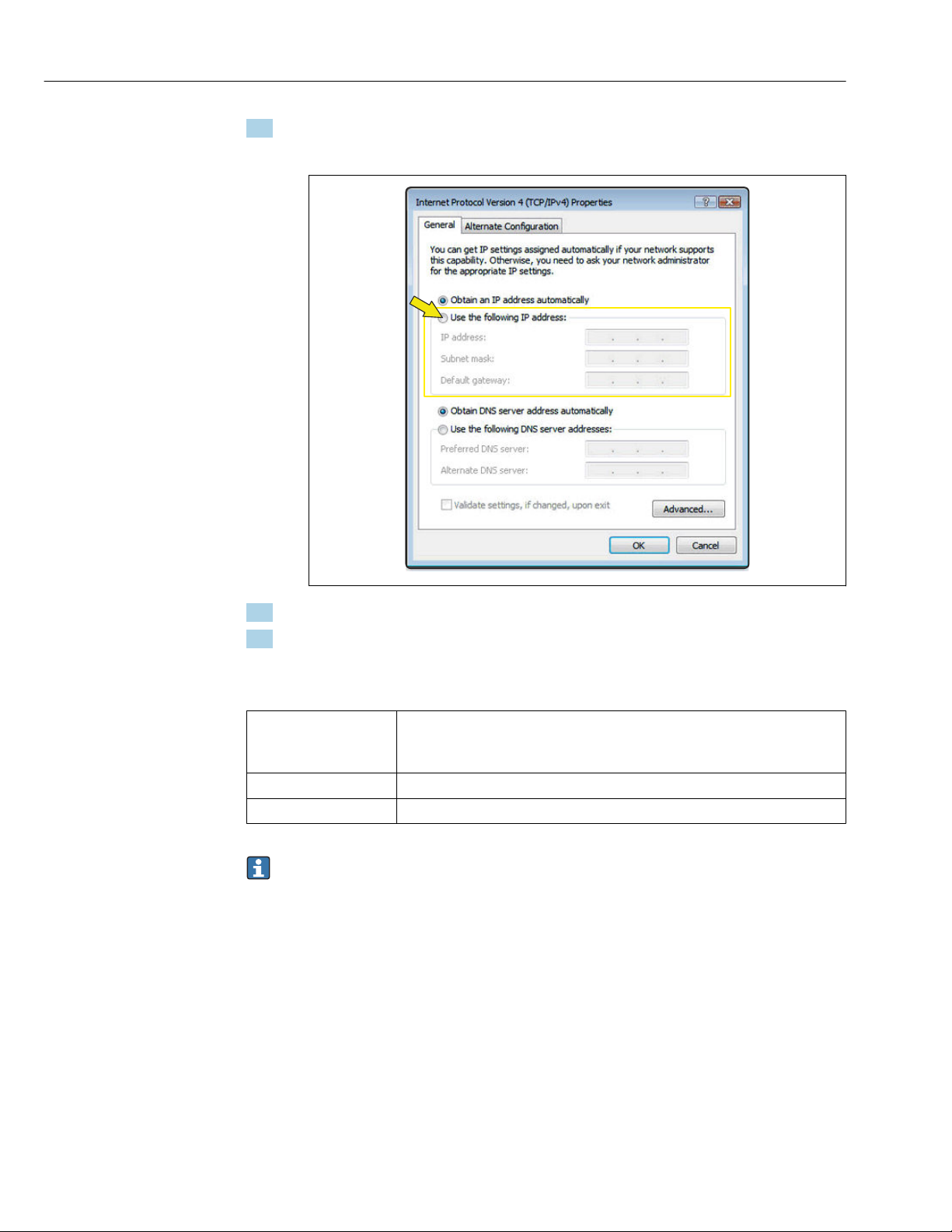
8. Click the Properties button.
The Internet Protocol Version 4 (TCP/IPv4) Properties window opens.
A0024309
9. In the General tab, select the Use the Following IP Address option.
10. Enter the IP address, subnet mask and default gateway as indicated in the following
table and then click Ok to confirm.
Standard settings for IP address, subnet mask and default gateway
IP address 192.168.1.XXX
For XXX all numerical sequences except: 0, 212 and 255 → e.g.
192.168.1.213
Subnet mask 255.255.255.0
Default gateway 192.168.1.212 or leave cells empty
The standard settings correspond to those for private networks. In the case of
Ethernet-based networks, the settings can deviate from these standard settings and
must be changed if necessary.
Proline Promass 500 Modbus RS485 Commissioning
15
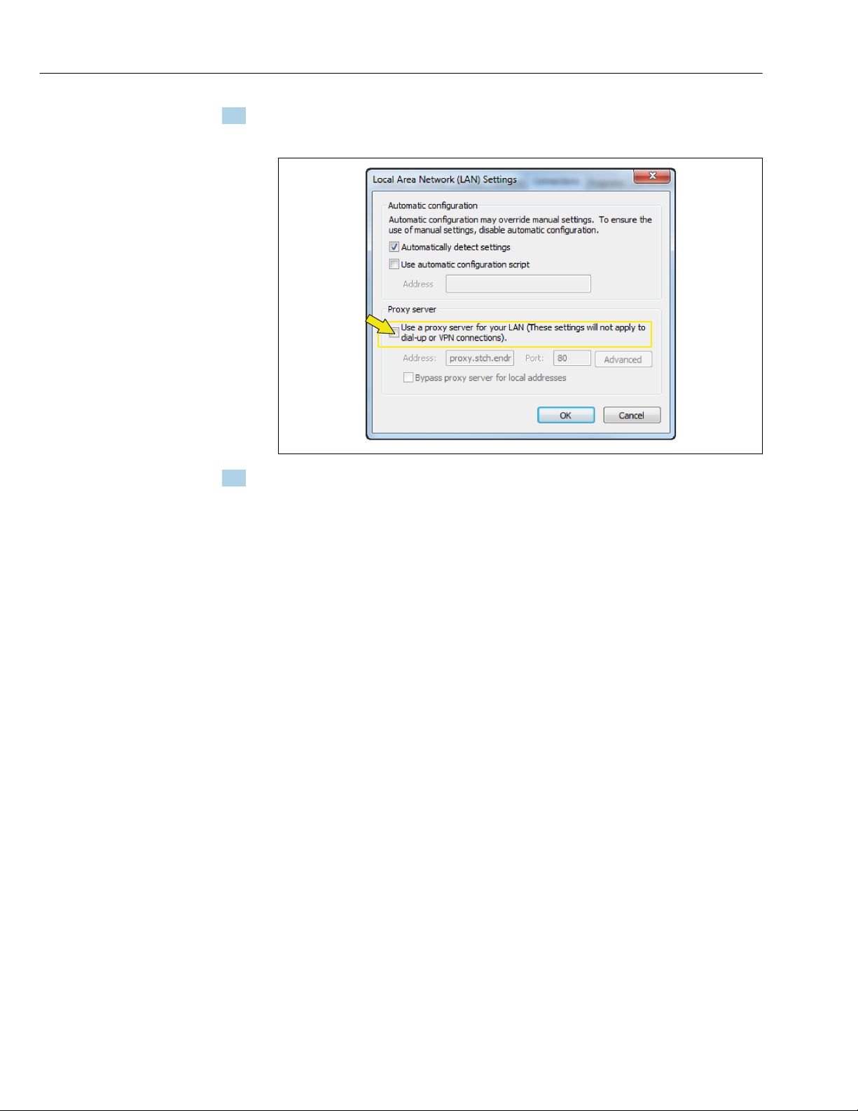
Changing the proxy server settings
To establish communication, the proxy server setting Use a Proxy Server for Your LAN must
be deselected for the Web browser.
To change the proxy server setting, appropriate user rights (e.g. administrator rights)
are required for the computer.
Changing the proxy server settings taking Internet Explorer as the sample browser
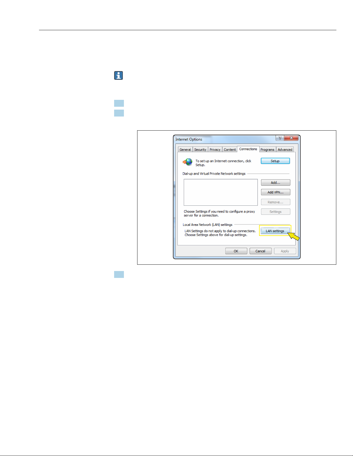
1. Open the Web browser.
2. In the Options menu, select the Internet Options item.
This opens a new window with the Internet options.
A0024310
3. Select the Connections tab.
Commissioning Proline Promass 500 Modbus RS485
16
4. Under Local Area Network Settings click the LAN Settings button.
This opens a new window with the Local Area Network Settings.
A0024311
5. Deselect the Use a Proxy Server for Your LAN checkbox and then click Ok to confirm.
4.2 Prerequisites - measuring device
4.2.1 Enabling the Web server
The Web server must be enabled in the measuring device (factory setting).
If the Web server is disabled it be enabled again via the Web server functionality
parameter (→ 22). To do so, users can choose from the following operation options:
• Local display
• Operating tool e.g. FieldCare, DeviceCare, AMS Device Manager , SIMATIC PDM
4.2.2 Determining the IP address of the measuring device
The IP address of the device is required to establish communication between the device
(Web server) and a computer (client). The device has the default fixed IP address:
192.168.1.212. This can be entered in the Web browser on the computer to establish
communication.
Using the local display or an operating tool
The IP address parameter can be used to determine the IP address via the local display or
via an operating tool e.g. FieldCare, DeviceCare, AMS Device Manager, SIMATIC PDM.
4.3 Connecting the computer to the measuring device
The measuring device can be connected to the computer via:
• Service interface (CDI-RJ45)
• WLAN interface

Proline Promass 500 Modbus RS485 Commissioning
17
4.3.1 Via service interface (CDI-RJ45)
Preparing the measuring device
Proline 500 – digital
1. Loosen the 4 fixing screws on the housing cover.
2. Open the housing cover.
3. The location of the connection socket depends on the measuring device and the
communication protocol:
Connect the computer to the RJ45 connector via the standard Ethernet connecting
cable → 8.
Proline 500
1. Depending on the housing version:
Release the securing clamp or securing screw of the housing cover.
2. Depending on the housing version:
Unscrew or open the housing cover.
3. The location of the connection socket depends on the measuring device and the
communication protocol:
Connect the computer to the RJ45 connector via the standard Ethernet connecting
cable → 8.
Configuring the Internet protocol of the computer
The following information refers to the default Ethernet settings of the device.
IP address of the device: 192.168.1.212 (factory setting)
NOTICE
Risk of electric shock! Components carry dangerous voltages!
‣Never open the measuring device while it is connected to the supply voltage.
‣The information and safety instructions in the Operating Instructions pertaining to the
measuring device must always be observed → 4.
1. Switch on the measuring device.
2. Connect to the computer using a cable → 8.
3. If a 2nd network card is not used, close all the applications on the notebook.
Applications requiring Internet or a network, such as e-mail, SAP applications,
Internet or Windows Explorer.
4. Close any open Internet browsers.
5. Configure the properties of the Internet protocol (TCP/IP) as defined in the table:
IP address 192.168.1.XXX; for XXX all numerical sequences except: 0, 212 and 255 → e.g.
192.168.1.213
Subnet mask 255.255.255.0
Default gateway 192.168.1.212 or leave cells empty

Commissioning Proline Promass 500 Modbus RS485
18
4.3.2 Via WLAN interface
Configuring the Internet protocol of the mobile terminal
NOTICE
If the WLAN connection is lost during the configuration, settings made may be lost.
‣Make sure that the WLAN connection is not disconnected while configuring the device.
NOTICE
In principle, avoid simultaneous access to the measuring device via the service
interface (CDI-RJ45) and the WLAN interface from the same mobile terminal. This
could cause a network conflict.
‣Only activate one service interface (CDI-RJ45 service interface or WLAN interface).
‣If simultaneous communication is necessary: configure different IP address ranges, e.g.
192.168.0.1 (WLAN interface) and 192.168.1.212 (CDI-RJ45 service interface).
Preparing the mobile terminal
‣Enable WLAN reception on the mobile terminal.
Establishing a connection from the mobile terminal to the measuring device
1. In the WLAN settings of the mobile terminal:
Select the measuring device using the SSID (e.g. EH_Promass_500_A802000).
2. If necessary, select the WPA2 encryption method.
3. Enter the password: serial number of the measuring device ex-works (e.g.
L100A802000).
LED on display module flashes: it is now possible to operate the measuring device
with the Web browser.
The serial number can be found on the nameplate.
To ensure the safe and swift assignment of the WLAN network to the measuring
point, it is advisable to change the SSID name. It should be possible to clearly assign
the new SSID name to the measuring point (e.g. tag name) because it is displayed as
the WLAN network.
Disconnecting
‣After configuring the device:
Terminate the WLAN connection between the operating unit and measuring device.
4.4 Establishing a connection to the Web server
4.4.1 Prerequisites
The IP settings in the measuring device and computer must match before a connection can
be established successfully. In particular this concerns the IP addressing and Web browser
settings.

Proline Promass 500 Modbus RS485 Commissioning
19
The following conditions must be met to connect:
• The Web server of the measuring device is enabled → 16.
• The IP address of the measuring device is known → 16.
• The computer used meets the requirements for hardware and software → 10.
• The measuring device and computer are connected to one another → 16
• The measuring device is switched on.
4.4.2 Starting the Web browser
If JavaScript cannot be enabled:
enter http://192.168.1.212/basic.html in the address line of the Web browser. A
fully functional but simplified version of the operating menu structure starts in the
Web browser.
When installing a new firmware version: To enable correct data display, clear the
temporary memory (cache) of the Web browser under Internet options.
1. Start the Web browser on the computer.
2. Enter the IP address of the Web server in the address line of the Web browser:
192.168.1.212
The login page appears.
If a login page does not appear, or if the page is incomplete → 27

Commissioning Proline Promass 500 Modbus RS485
20
4.5 Setting the IP address
The IP address of the measuring device is required to establish communication between
the measuring device (Web server) and a computer (client).
Assign or specify the IP address via: Description
The use of the standard IP address 1) • The measuring device uses the fixed IP address: 192.168.1.212
• The device is connected via the CDI-RJ45 service interface.
1) Factory setting
4.6 Overview of the Web server parameters
4.6.1 Language
Navigation
"Operation" menu → Web server language
Parameter overview with brief description
Parameter Description Selection Factory setting
Web server language Set web server language. • English
• Deutsch *
• Français *
• Español *
• Italiano *
• Nederlands *
• Portuguesa *
• Polski *
• русский язык (Russian) *
• Svenska *
• Türkçe *
•中文 (Chinese) *
•日本語 (Japanese) *
•한국어 (Korean) *
• Bahasa Indonesia *
• tiếng Việt (Vietnamese) *
• čeština (Czech) *
English
* Visibility depends on order options or device settings
4.6.2 "Web server" submenu
Navigation
"Expert" menu → Communication → Web server
‣Web server
Web server language (7221) → 21
MAC address (7214) → 21
Other manuals for Proline Promass 500
1
Table of contents
Other TechnipFMC Server manuals


