Technische Alternative RAS+DL User manual

ta.co.at
RAS+DL
ROOM SENSOR WITH REMOTE DISPLAY
Version 2.10.2
Operation
Programming
Installation instructions
EnglishManual Version 2.10.2


3
Table of contents
Function description . . . . . . . . . . . . . . . . . . . . . . . . . . . . . . . . . . . . . . . . . . . . . . . . . . . . . . . . . . . 4
Programming manual . . . . . . . . . . . . . . . . . . . . . . . . . . . . . . . . . . . . . . . . . . . . . . . . . . . . . . . . . . . 5
Menu – general overview . . . . . . . . . . . . . . . . . . . . . . . . . . . . . . . . . . . . . . . . . . . . . . . . . . . . . . . . . . . . 6
Menu overview for UVR16x2, RSM610, CAN-I/O45 and UVR1611 . . . . . . . . . . . . . . . . . . . . . . . . . . . . . . . .6
Menu overview for ESR21 (min. version 5.0) and ESR31, UVR61-3 (min. version 8.3), UVR63 (min. version
1.5) . . . . . . . . . . . . . . . . . . . . . . . . . . . . . . . . . . . . . . . . . . . . . . . . . . . . . . . . . . . . . . . . . . . . . . . . . . . . . . .7
Menu overview of all other controllers . . . . . . . . . . . . . . . . . . . . . . . . . . . . . . . . . . . . . . . . . . . . . . . . . . . .8
Menu CONFIG . . . . . . . . . . . . . . . . . . . . . . . . . . . . . . . . . . . . . . . . . . . . . . . . . . . . . . . . . . . . . . . . . . . . . 9
Language selection SPR DE/LAN EN . . . . . . . . . . . . . . . . . . . . . . . . . . . . . . . . . . . . . . . . . . . . . . . . . . . . .9
Time interval for continuous display TIME N . . . . . . . . . . . . . . . . . . . . . . . . . . . . . . . . . . . . . . . . . . . . . . .9
Time before jumping back to the first display TIME R . . . . . . . . . . . . . . . . . . . . . . . . . . . . . . . . . . . . . . .10
Address in the DL-bus network DL ADR . . . . . . . . . . . . . . . . . . . . . . . . . . . . . . . . . . . . . . . . . . . . . . . . . .10
Index specification . . . . . . . . . . . . . . . . . . . . . . . . . . . . . . . . . . . . . . . . . . . . . . . . . . . . . . . . . . . . . . . . . .11
Entry of an offset value for sensor correction OFFSET . . . . . . . . . . . . . . . . . . . . . . . . . . . . . . . . . . . . . . .12
Display of operating mode symbols SYMB . . . . . . . . . . . . . . . . . . . . . . . . . . . . . . . . . . . . . . . . . . . . . . . .13
Measurement display VALUES . . . . . . . . . . . . . . . . . . . . . . . . . . . . . . . . . . . . . . . . . . . . . . . . . . . . . . . . .13
Password allocation PASSW . . . . . . . . . . . . . . . . . . . . . . . . . . . . . . . . . . . . . . . . . . . . . . . . . . . . . . . . . . .14
Sensor restart RSTART . . . . . . . . . . . . . . . . . . . . . . . . . . . . . . . . . . . . . . . . . . . . . . . . . . . . . . . . . . . . . . .14
Menu VALUES . . . . . . . . . . . . . . . . . . . . . . . . . . . . . . . . . . . . . . . . . . . . . . . . . . . . . . . . . . . . . . . . . . . . 15
Menu sensor values SENSOR . . . . . . . . . . . . . . . . . . . . . . . . . . . . . . . . . . . . . . . . . . . . . . . . . . . . . . . . . .15
Menu output statuses OUTPUT . . . . . . . . . . . . . . . . . . . . . . . . . . . . . . . . . . . . . . . . . . . . . . . . . . . . . . . . .16
Menu speed stages SPEED (only UVR1611) . . . . . . . . . . . . . . . . . . . . . . . . . . . . . . . . . . . . . . . . . . . . . . .17
Menu heat quantity counter POWER . . . . . . . . . . . . . . . . . . . . . . . . . . . . . . . . . . . . . . . . . . . . . . . . . . . . .18
Menu external sensors NETW (ESR21 > V5.0, ESR31, UVR61-3 > V8.3, UVR63 > V 1.5) . . . . . . . . . . . . . .19
Menu analogue CAN network inputs ANALNW (only UVR1611) . . . . . . . . . . . . . . . . . . . . . . . . . . . . . . . .20
Menu digital CAN network inputs DIGINW (only UVR1611) . . . . . . . . . . . . . . . . . . . . . . . . . . . . . . . . . . .21
Menu symbol allocation SYMB . . . . . . . . . . . . . . . . . . . . . . . . . . . . . . . . . . . . . . . . . . . . . . . . . . . . . . . . .22
Deleting or changing a symbol allocation . . . . . . . . . . . . . . . . . . . . . . . . . . . . . . . . . . . . . . . . . . . . . . . . .24
Display of DL outputs . . . . . . . . . . . . . . . . . . . . . . . . . . . . . . . . . . . . . . . . . . . . . . . . . . . . . . . . . . . . . . 25
Programming . . . . . . . . . . . . . . . . . . . . . . . . . . . . . . . . . . . . . . . . . . . . . . . . . . . . . . . . . . . . . . . . . . . . . .25
Reset to factory settings . . . . . . . . . . . . . . . . . . . . . . . . . . . . . . . . . . . . . . . . . . . . . . . . . . . . . . . . . . . . 26
Operation . . . . . . . . . . . . . . . . . . . . . . . . . . . . . . . . . . . . . . . . . . . . . . . . . . . . . . . . . . . . . . . . . . 27
Room sensor with UVR16x2, RSM610, CAN-I/O45, UVR1611 (> A3.00 and serial number >13285) or with
UVR63-H (> V7.2) . . . . . . . . . . . . . . . . . . . . . . . . . . . . . . . . . . . . . . . . . . . . . . . . . . . . . . . . . . . . . . . . . . .27
Use as a remote control . . . . . . . . . . . . . . . . . . . . . . . . . . . . . . . . . . . . . . . . . . . . . . . . . . . . . . . . . . . . . .28
Room sensors with other controllers . . . . . . . . . . . . . . . . . . . . . . . . . . . . . . . . . . . . . . . . . . . . . . . . . . . .28
Installation . . . . . . . . . . . . . . . . . . . . . . . . . . . . . . . . . . . . . . . . . . . . . . . . . . . . . . . . . . . . . . . . . 28
Electrical connections . . . . . . . . . . . . . . . . . . . . . . . . . . . . . . . . . . . . . . . . . . . . . . . . . . . . . . . . . . . . . . 29
Technical data . . . . . . . . . . . . . . . . . . . . . . . . . . . . . . . . . . . . . . . . . . . . . . . . . . . . . . . . . . . . . . . 29

4
Function description
The room sensor RAS+DL was especially developed for Technische Alternative control units and is
intended for installation in living areas (reference space). The room sensor should not be installed
near a source of heat or a window. It is only suitable for operation in dry rooms.
The RAS+DL transmits the room temperature, relative room humidity, ambient air pressure, absolute
humidity and the dew point, as well as the operating mode and the correction factor for the set value
(+/-4 K) to the controller via the bidirectional data link (DL-bus). Using the DL-bus, it is also possible
to display controller‘s sensor values, output states, heat meter outputs and network inputs directly
on the RAS+DL (on its display). By programming the sensor, display of values and symbols can be
customized. Moreover, there is a choice between automatic or manual scrolling through displays.
The sensor RAS+DL can be used as a room sensor with remote display with the following control-
lers:
• UVR16x2
• RSM610
• CAN-I/O 45
• UVR1611, minimum version A3.00 and minimum serial number 13286
• UVR63-H minimum version 7.2
• UVR63 minimum version 1.0
• UVR61-3 minimum version 5.0
• ESR31 minimum version 1.0
• ESR21 minimum version 5.0
The RAS+DL can also be used as a remote display device with the following controllers (no function-
ality as sensor):
• UVR 31
• UVR 42
• UVR 64
• HZR 65
• UVR 1611 < version A3.00
• UVR 63-H < version 5.0
• UVR 61-3 < version 5.0
• ESR 21 < version 5.0
These controllers do not yet have a bidirectional data link.
Caution:
When used with UVR16x2/UVR65/UVR67, the DL data output of the controller must be set to Yes.

5
Programming manual
Only the basic values are displayed in the factory settings of the room sensor:
• Room temperature
• Relative room humidity
• Ambient air pressure
• Dewpoint
• Nominal value adjustment (+/- 4K)
With the aid of programming, other values can be displayed.
RAS+DL can the configured using the key and the set up to display further values.
The following symbols are used in the menu descriptions to differentiate between long and short key
presses:
Long key press (at least 2 seconds)
Short key press
Multiple short key presses
Further information about the menu views:
Numbers in red mean that they flash on the display.
Exiting a menu level is always possible from the EXIT display indication via a long
key press.
Access to the programming level is only possible with the slider switch set to the „Standby“ po-
sition (leftmost).

6
Menu – general overview
The displayed menu options are matched to the respective controller types:
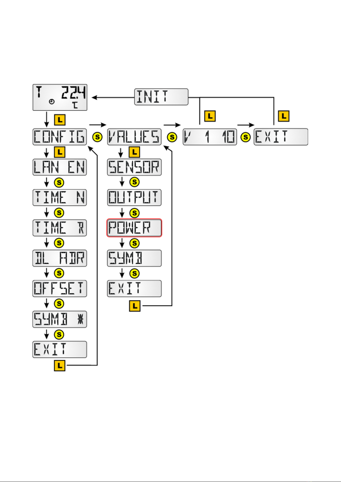
Menu overview for UVR16x2, RSM610, CAN-I/O45 and UVR1611
General sensor settings are adjusted in the menu section „CONFIG“.
Values and symbols to displayed are selected in the menu section „VALUES“.
V 1 10 = Sensor version number

7
Menu overview for ESR21 (min. version 5.0) and ESR31, UVR61-3
(min. version 8.3), UVR63 (min. version 1.5)
General sensor settings are adjusted in the menu section „CONFIG“.
Values and symbols to displayed are selected in the menu section „VALUES“.
V 1 10 = Sensor version number
8
Menu overview of all other controllers
General sensor settings are adjusted in the menu section „CONFIG“.
Values and symbols to displayed are selected in the menu section „VALUES“.
The menu option „POWER“* (heat meter) is only displayed for controllers that have this functionality.
V 1 10 = Sensor version number

9
Menu CONFIG
The following settings are made here
• Language selection SPR DE / LAN EN
• Time interval for continuous display TIME N
• Time before resetting to the 1st display TIME R
• Address in the DL-bus network DL ADR
• Entry of an offset value for sensor correction OFFSET
• Activation/deactivation of symbols SYMB
• Changes regarding displayed values WERTE
• Setting a password for access to the menu KONFIG, PASSW
• Restarting the sensor RSTART
• Display/hide operation mode symbols SYMB
Language selection SPR DE/LAN EN
Switching between German (DE) and English
(EN)
Factory setting: DE
To activate the language selection the RAS+DL must be initialised by scrolling forward into the dis-
play level.
Time interval for continuous display TIME N
Entry 0 = no automatic switching between displays
Factory settings: 0
„0“ flashes after a long key press
Selection of the desired time via a short key press.
Confirmation of the desired time via a long key press.
Entry 15 = The value display scrolls forward to the next
display every 15 seconds
Adjustment range: 0-99 sec in steps of 1 second

10
Time before jumping back to the first display TIME R
Entry 0 = no jumping back to the first display
Factory setting: 0
„0“ flashes after a long key press
Selection of the desired time via a short key press. Confirma-
tion of the desired time via a long key press.
Entry 60 = After 60 seconds without pushing of the button
jumping back from one of the additional programmed values
to the first display value (room temperature) occurs. Adjust-
ment range: 0-200 sec in steps of 1 second.
The jump back occurs only from the additionally programmed display values, not from the one of the
base values.
Address in the DL-bus network DL ADR
Upon request by controller ESR31, UVR63 (min. version 1.0), ESR21, UVR61-3 and UVR63-H (min.
version 5.0), UVR1611 (min. version A3.00), plus UVR16x2, RSM610 and CAN-I/O45, the sensor re-
turns the corresponding measured value. The request consists of the address of the sensor and the
index number of a measured value.
Each device in the DL-Bus network must have its own ad-
dress so that it can send values to a controller.
Factory setting: DL 1
„1“ flashes after a long key press
Selection of the desired address via a short key press.
Adjustment range: DL 1 to DL 8
Confirmation of the desired address via a long key press.
Among those controllers that have no bidirectional data link (those for which the RAS+DL can only
be used as a remote display, e.g. HZR65), this menu option is still displayed but has no effect and
should therefore be ignored.
Note: Of the continuous display TIME N is activated (≠0), then TIME R has no effect.

11
Index specification
To process sensor values on the controller, specification and selection of the sensor address (1-8)
and the index (1-11) is necessary.
Indices can be selected for the following values:
UVR16x2, RSM610, CAN-I/O45: The measured values are parameterised in the menu „DL bus“.
In TAPPS2, a DL input is programmed with the corresponding address and index.
If the measured variable is set to "Automatic", no further settings are required here.
Index Value
1Room temperature with offset values for +/- adjustment the dip switch (to evaluate „RAS“
on controllers UVR1611 and UVR63-H (min. version 7.2))
2Measured room temperature (without offset values of the +/- adjustment and the slider
switch (e.g. for the controller UVR61-3)
3Relative room humidity
4Dew point temperature
5Fixed value 20°C with offset values for +/- adjustment and the dip switch (used as remote
adjuster for controllers UVR16x2, UVR1611 and UR63-H)
6Unused
7Air pressure in mbar
8Absolute humidty
9/10 Unused
11 Room temperature with offset values for +/- adjustment and the dip switch (for evaluating
„RAS“ in controllers UVR16x2, RSM610, CAN-I/O45)
12 Room temperature without offset values of +/- adjustment, with dip switch position (only
x2 devices)
13 Offset value of +/- adjustment, range -4 to +4 K (only x2 devices)
14 Serial number of room sensor (only x2 devices)
15 Software version of room sensor (only x2 devices)
12
ESR21, ESR31, UVR61-3, UVR63 and UVR63-H
Adjustment of the measurements takes place in the menu EXT DL (external sensors)
Example: The external sensor 1 has address 1, the measured room temperature
is imported without offset values (index 2).
In the controllers ESR31, UVR61-3, UVR63 and UVR63-H (version 5.0 up to 7.1), only the measured
room temperature can be evaluated without offset values (index 2); the slider switch and the rotary
knob have no purpose for these controllers. This value can subsequently be allocated to a sensor val-
ue (menu ENTER/Men – SENSOR).
The room humidity value is indicated in these controllers as a dimensionless value without a decimal
point (e.g. 35.5% -> Controller display: 355).
The values of indices 1 and 5 would be indicated with "999” and therefore cannot be used.
The menu option "EXT DL" is only available in the following controllers:
• UVR63-H from version 5.0
• UVR63 from version 1.0
• UVR61-3 from version 5.0
• ESR31 from version 1.0
• ESR21 from version 5.0
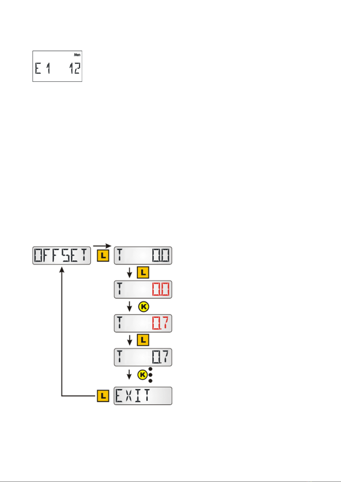
Entry of an offset value for sensor correction OFFSET
Offset values can be set for the measured values for temperature, room humidity and ambient air
pressure.
Entry T 0.0 = no offset value selected, therefore
no sensor correction
Factory setting: T 0.0
After a long key press "0.0" flashes
Selection of the desired offset value via a short
key press.
Confirmation of the desired value via a long key
press
Entry T +0.7 = The room temperature value dis-
played and transmitted to the controller is in-
creased by 0.7 K.
Adjustment range: - 4,0K to +4,0K
Further short presses of the button will display
the offset values for room humidity and air pres-
sure (P).

13
Example: If an offset value of 0.7K is set and a temperature of 21.0°C is measured, 21.7°C is indicat-
ed (index values 1 and 2). This corrected value is used in the sequence for all calculations and for-
warded to the controller.
Among those controllers that have no bidirectional data link (e.g. HZR65), i.e. those for which the
RAS+DL can only be used as a remote display, this menu option is still displayed but has no effect
and can therefore be disregarded.
Display of operating mode symbols SYMB
In this menu, the symbols for the operating mode can be hidden.
Press and hold the button for a long
time to select the required display.
Measurement display VALUES
Not to be confused with the VALUES menu, this is a sub-item in the CONFIG menu
The following values are displayed in sequence:
•RRH Relative humidity in room
•ARF Absolute humidity in room
•P Ambient air pressure
•C Temperature
•DP Dew point
A long click on a value shows or hides the value.
An asterisk on the right-hand side of the screen
means the value is shown.
Showing/hiding affects the displays in the main
level.

14
Password allocation PASSW
The purpose of this password is to block access
to the CONFIG and VALUES menus. For access,
enter the password set here. If 0000 is entered,
no password is required. While the password is
shown, long clicks can be used to go through the
individual character places (active place flash-
es) and a short click increases a place by 1. A
long click while the last place is active ends the
entry process.
Sensor restart RSTART
A long click on RSTART restarts the sensor. The
REBOOT display appears, followed by INIT, and
then the view switches to the main level.

15
Menu VALUES
This is where the display is selected:
• Sensor values SENSOR
• Output statuses OUTPUT
• Speed stages SPEED (only UVR16x2, RSM610, CAN-I/O45 and UVR 1611)
• Heat quantity counter POWER (only for controllers with a heat quantity counter)
• External sensors NETW (only ESR31 and ESR21 from version. 5)
• Analog network inputs ANALNW (only UVR1611)
• Digital network inputs DIGINW (only UVR1611)
• Symbol allocation SYMB
Menu sensor values SENSOR
Access the menu via a long key press.
Selection via a long key press at the sensor in
question. The selection is indicated by a star.
Depending on the controller type, up to 16 sen-
sor values can be displayed.
Display examples:
Sensor 1 has a currently measured value of 94.1 °C.
For values from sensors that are not temperature sensors, no units are dis-
played.
Input values for inputs that are not parametrised are shown with dashes.
Digital inputs are shown with "ON" or "OFF".

16
Menu output statuses OUTPUT
Access the menu via a long key press.
Selection via a long key press on the relevant
output. The selection is indicated by a star sym-
bol.
Depending on the controller type, up to 14 out-
put statuses can be displayed.
Analogue outputs 15 and 16 of controllers
UVR16x2 and UVR1611 cannot be displayed.
The output statuses of outputs 12 – 14 of con-
troller UVR16x2 are displayed correctly only if
they are defined as switching outputs.
Display example:
Output O1 is switched off.
If the heating controller UVR63-H’s outputs O2 and O3 are used for actuation of the mixer motor, then
the display for these outputs always remains on "OFF".
For the controllers UVR61-3, UVR63, UVR63-H, ESR21 and ESR31 after display
of the outputs the speed stage of the adjustable outputs can be displayed.
For controllers UVR61-3, UVR63, UVR63-H and ESR31 after display of the speed
stage, the value of control output 1 (ANL1) can be displayed.

17
Menu speed stages SPEED (only UVR1611)
Access the menu via a long key press.
Selection via a long key press on the relevant
output. The selection is indicated by a star. The
speed of this output is displayed after all the
other displays have been displayed.
Display example:
The speed stage of output 1 is 25.

18
Menu heat quantity counter POWER
This menu option is only displayed for controllers with a heat quantity counter.
Access the menu via a long key press.
Selection via a long key press of the value of the
respective heat quantity counter. The selection
is indicated by a star.
P1...4 = current output in kW
KW1...4 = metered heat quantity in kWh
Once 999 kWh is reached, the coun-
ter resets to 0 and the MWh display
is increased by 1.
MW1...4 = metered heat quantity in MWh
1...4 = Number of the heat quantity coun-
ter, for controllers UVR16x2 and
UVR1611 in the programming se-
quence
Display examples:
Current output of the heat quantity counter 1 in kW. For 4 figure numbers to be
displayed, "P1" and “17,28” flash alternately.
Metered heat quantity of the heat quantity counter 1 in kWh. For 3 figure num-
ber to be displayed, "KW1" and “385” flash alternately.
Metered heat quantity of the heat quantity counter 1 in MWh.

19
Menu external sensors NETW (ESR21 > V5.0, ESR31, UVR61-3 > V8.3, UVR63 > V 1.5)
This selection is only possible for the controllers listed above, as only these controllers can display
external sensors via the data link.
Access the menu via a long key press.
Selection via a long key press at the relevant ex-
ternal sensor. The selection is indicated by a
star.
Up to 6 external sensors can be displayed.
Display example:
Temperature display at the external sensor 1,
"EXT1" and "22.6°C" flash alternatively.

20
Menu analogue CAN network inputs ANALNW (only UVR1611)
This selection is only possible for the controller UVR1611. For output 14, the query
NETW.IP.=>DL.: must be set to „yes“.
Access the menu via a long key press.
Selection via a long key press t the relevant an-
alogue network input. The selection is indicat-
ed by a star.
Up to 16 analogue network inputs can be dis-
played.
Display example:
Current value of the analogue network input 1. For 3 figure numbers to be dis-
played, "NA1" flashes alternately with the value "72.3".
Table of contents
Other Technische Alternative Accessories manuals


Popular Accessories manuals by other brands


WIKA
WIKA CPT7000 operating instructions

PREMIUM FRAGRANCES
PREMIUM FRAGRANCES TINY 2 user manual

Evolur
Evolur Infinity Twin Connector 366 user manual

IFM Electronic
IFM Electronic SU7000 operating instructions

HYDRO-RAIN
HYDRO-RAIN HRC-100-RS-RF instruction manual

PRIMAVERA
PRIMAVERA AromaStream To Go GB-332 Important Information About Usage and Cleaning


