Technische Alternative RAS-PLUS User manual
RAS-PLUS (/F)
Version 1.10 EN
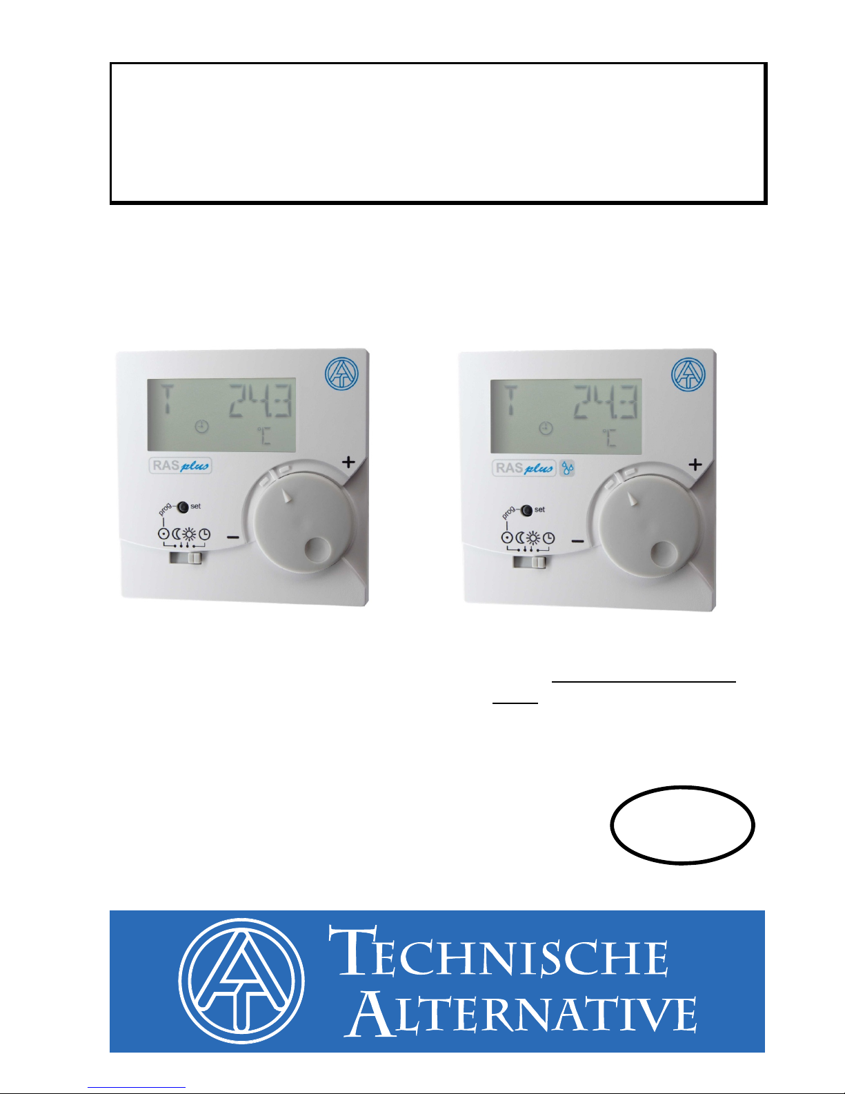
Room sensor
with remote display
RAS-PLUS = Room sensor with
temperature measurement and remote
display
RAS-PLUS/F = Room sensor with
temperature and humidity measure-
ment and remote display
Operation
Programming
Installation instructions
en


Table of Contents
Function description ........................................................................................4
Programming manual.......................................................................................5
Menu – general overviews................................................................................................6
Menu overview UVR16x2, RSM610, CAN-I/O45 and UVR1611.....................................6
Menu overview for ESR21 (from version 5.0) and ESR31, UVR61-3 (from version 8.3),
UVR63 (from version 1.5)................................................................................................7
Menu overview for all other controllers............................................................................8
Menu CONFIG....................................................................................................................9
Language selection SPR DE/LAN EN.............................................................................9
Time interval for continuing display TIME N....................................................................9
Time before jumping back to the 1st display TIME B ....................................................10
Address in the DL-bus network DL ADR .......................................................................11
Index specification.........................................................................................................12
Entry of an offset value for sensor correction OFFSET.................................................13
Display of operating mode symbols SYMB ...................................................................14
Menu VALUES..................................................................................................................15
Menu sensor values SENSOR......................................................................................15
Menu output statuses OUTPUT ....................................................................................16
Menu speed stages SPEED (only UVR1611) ...............................................................17
Menu heat quantity counter POWER ............................................................................18
Menu external sensors NETW (only ESR21 (from version 5.0), ESR31, UVR61-3 (from
version 8.3), UVR63 (from version 1.5))........................................................................19
Menu analog CAN network inputs ANALNW (only UVR1611) ......................................20
Menu digital CAN network inputs DIGINW (only UVR1611)..........................................21
Menu symbol allocation SYMB......................................................................................22
Deleting or changing a symbol allocation:.....................................................................24
Reset to factory setting...................................................................................................25
Operation.........................................................................................................26
Room sensor with UVR16x2, RSM610, CAN-I/O45, UVR1611(from vers. A3.00 and
serial number 13286) or with UVR63-H(from vers. 7.2) ................................................26
Use as a remote control..................................................................................................27
Room sensors with other controllers............................................................................27
Installation.......................................................................................................27
Electrical connections ....................................................................................................27
Technical data.................................................................................................27

4
Function description
The room sensor RAS-PLUS was specially developed for Technical Alternative control
units and is intended for mounting in the living area (reference space). The room sensor
should not be installed near a source of heat or near a window. It is only suitable for opera-
tion in dry rooms.
The RAS-PLUS transmits the room temperature, relative room humidity (only RAS-PLUS/F)
and the dew point (only RAS-PLUS/F), the operating mode and the correction value for the
nominal value (+/- 5K) to the controller via the bidirectional data link (DL-bus). Using the DL-
bus it is also possible to display controller sensor values, output states, heat quantity counter
outputs and network inputs at the RAS-PLUS (remote display). Programming of the sensor
permits the setting of which values and symbols are to be output to the display. Moreover
there is a choice between automatic or manual scrolling between the displays.
The sensor RAS-PLUS can be used with the following controllers as a room sensor with
remote display:
UVR 16x2
RSM 610
CAN-I/O 45
UVR 1611 from version A3.00 and serial number13286
UVR 63-H from version 7.2
UVR 63 from version 1.0
UVR 61-3 from version 5.0
ESR 31 from version 1.0
ESR 21 from version 5.0
Moreover the RAS-PLUS can also be used with the following controllers as a remote dis-
play device (without sensor functions):
UVR 31
UVR 42
UVR 64
HZR 65
UVR 1611 < version A3.00
UVR 63-H < version 5.0
UVR 61-3 < version 5.0
ESR 21 < version 5.0
These controllers do not have a bidirectional data link.

5
Programming manual
Only the basic values are displayed in the factory setting of the room sensor:
Room temperature
Relative Room humidity (only RAS-PLUS/F)
Nominal value adjustment (+/- 5K)
With the aid of programming other values can be displayed.
Access to the programming level is only possible from the "Standby" position
(extreme left) of the slider switch.
RAS-PLUS can be configured using the key and set up to display further values.
The following symbols are used in the menu descriptions to differentiate between long and
short key presses:
Long key press (at least 2 seconds)
Short key press
Multiple short key presses
Further information about the menu views:
Red printed numbers or symbols mean that they flash in the display.
Exiting from a menu level is always only possible from the "EXIT" display
indication by a long key press.
6
Menu – general overviews
The displayed menu options are matched to the respective controller types:
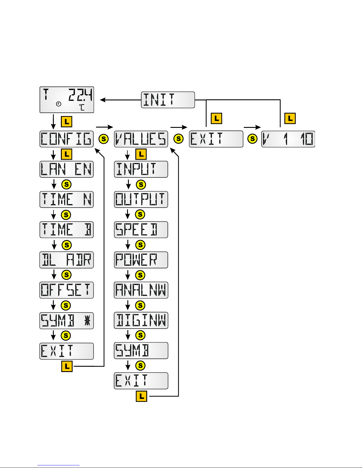
Menu overview UVR16x2, RSM610, CAN-I/O45 and UVR1611
In the menu section "CONFIG" gen-
eral sensor settings are adjusted.
The selection of the values and sym-
bols to be displayed takes place in
the menu section "VALUES".
V 1 10 = Sensor version number

7
Menu overview for ESR21 (from version 5.0) and ESR31, UVR61-
3 (from version 8.3), UVR63 (from version 1.5)
In the menu section "CONFIG" gen-
eral sensor settings are adjusted.
The selection of the values and sym-
bols to be displayed takes place in
the menu section "VALUES".
V 1 10 = Sensor version number

8
Menu overview for all other controllers
In the menu section "CONFIG" gen-
eral sensor settings are adjusted.
The selection of the values and sym-
bols to be displayed takes place in
the menu section "VALUES".
The menu option "POWER" (heat
quantity counter) is only displayed
with those controllers that have this
function.
V 1 10 = Sensor version number
9
Menu CONFIG
The following settings are made here:
Language selection SPR DE / LAN EN
Time interval for continuing display TIME N
Time before jumping back to the 1st display TIME B
Address in the DL-bus network DL ADR
Entry of an offset value for sensor correction OFFSET
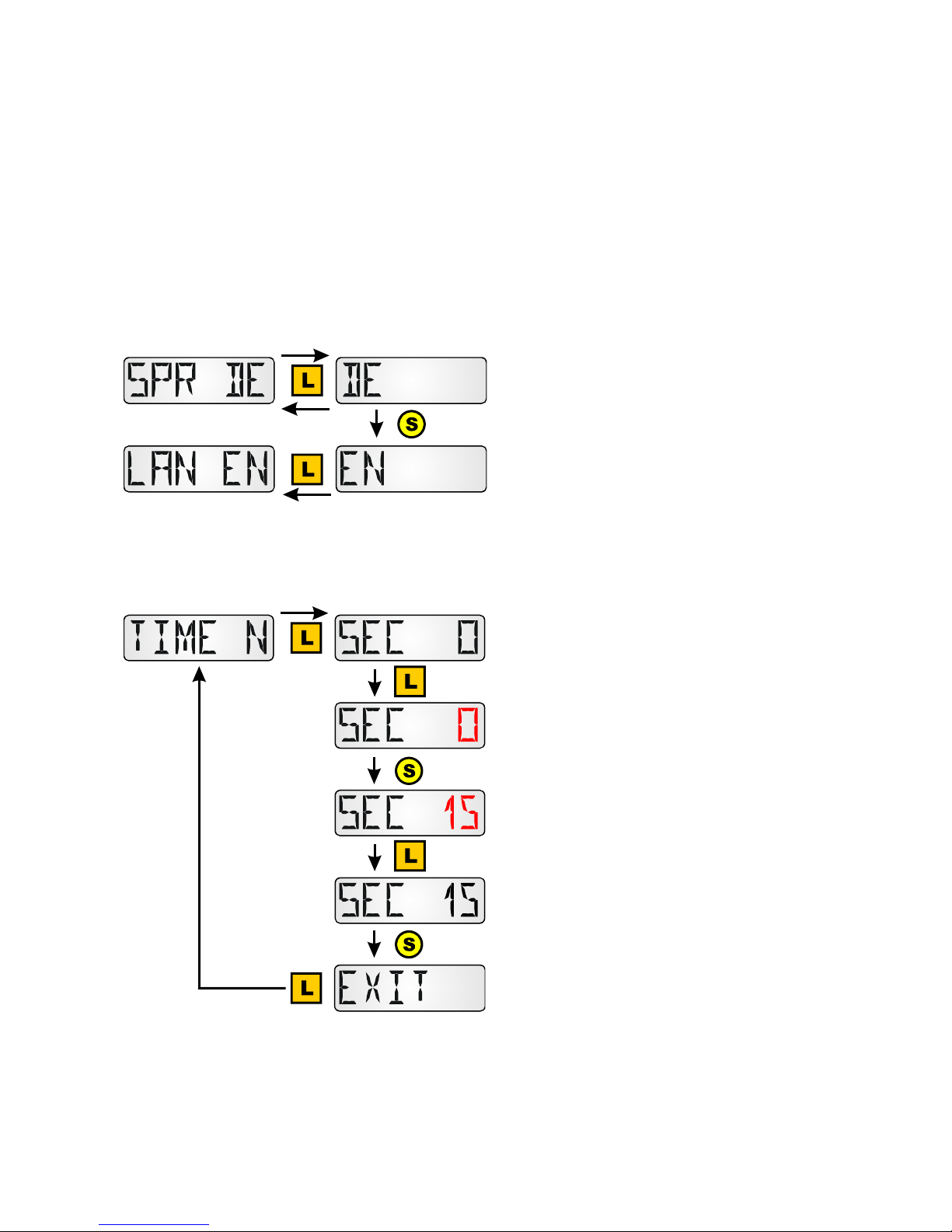
Language selection SPR DE/LAN EN
Switchover between German (DE) and
English (EN)
Factory setting: DE
To activate the language selection the RAS-PLUS must be initialised by scrolling forward in
the display level.
Time interval for continuing display TIME N
Entry 0 = no automatic forwarding between
the displays
Factory setting: 0
After a long key press "0" flashes
Selection of the desired time by a short key
press.
Confirmation of the desired time by a long
key press.
Entry 15 = The value display scrolls for-
wards every 15 seconds to the next display.
Adjustment range: 0 – 99 sec in second
steps
10
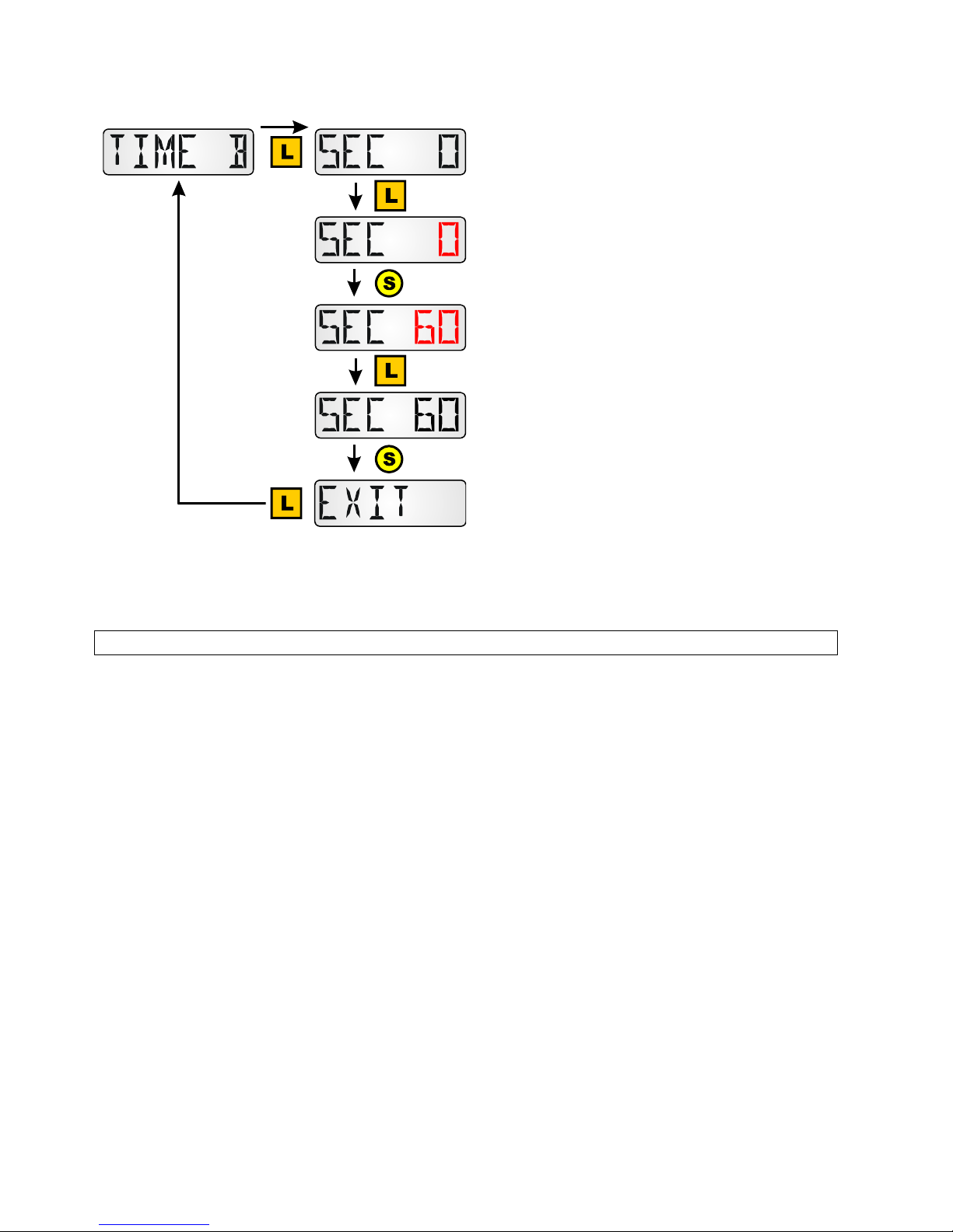
Time before jumping back to the 1st display TIME B
Entry = 0 There is no jump back of the dis-
play to the 1st value.
Factory setting: 0
After a long key press "0" flashes
Selection of the desired time by a short key
press.
Confirmation of the desired time by a long
key press.
Entry 60 = After 60 seconds without activa-
tion of the key button jumping back from
one of the additional programmed values to
the first display value (room temperature)
occurs. Adjustment range: 0 – 100 sec in
10 second steps
The jump back occurs only from the additionally programmed display values, not from one of
the base values.
Note: Only one of the two time options TIME N or TIME B should be selected.
11
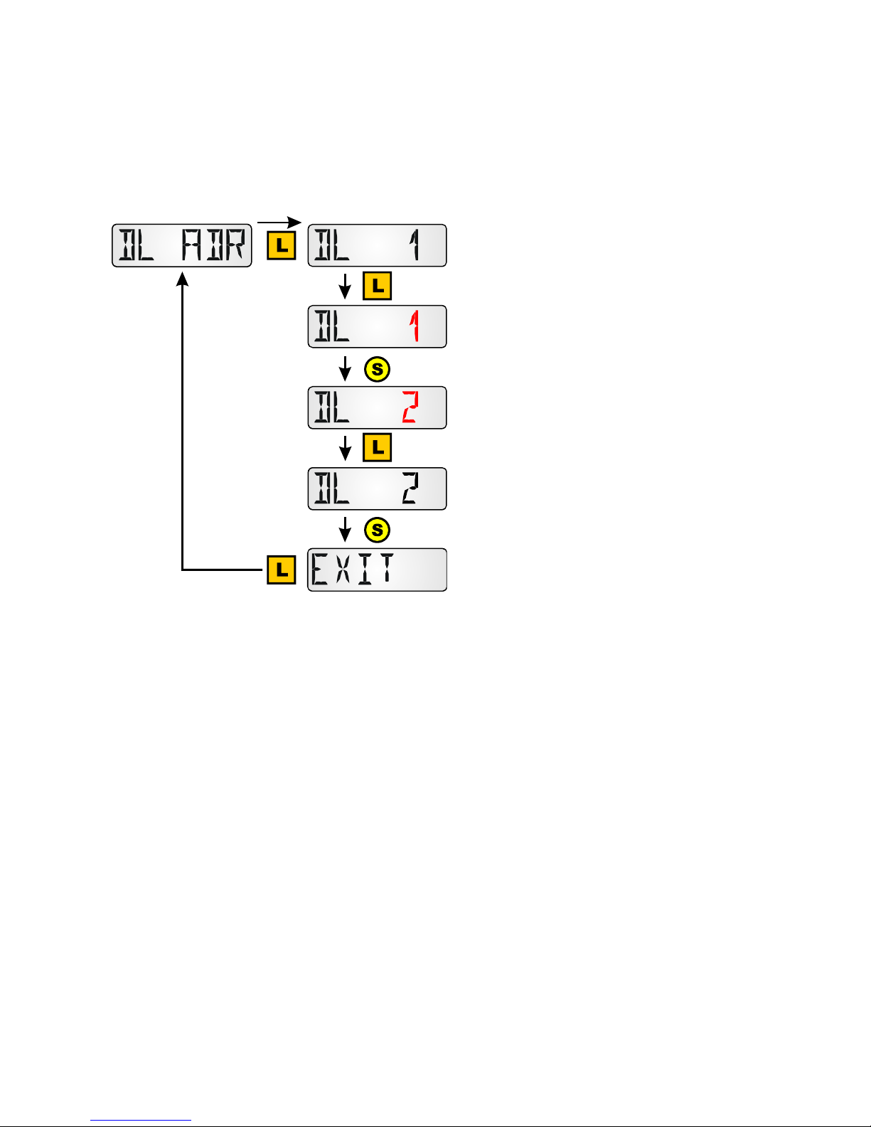
Address in the DL-bus network DL ADR
Upon querying by the controller ESR31, UVR63 (from version 1.0), ESR21, UVR61-3 and
UVR63-H (from version 5.0), UVR1611 (from version A3.00), plus UVR16x2, RSM610 and
CAN-I/O45 the sensor returns the corresponding measured value. The request is made up of
the address of the sensor and index of a measured value recorded there.
Each member of the DL-bus network must
have its own address so that it can send
values to a controller.
Factory setting: DL 1
After a long key press "1" flashes
Selection of the desired address by a short
key press.
Adjustment range: DL 1 to DL 8
Confirmation of the desired address by a
long key press.
Amongst those controllers that have no bidirectional data link (e.g. HZR65), i.e. amongst
those for which the RAS-PLUS can only be used as a remote display, this menu option is
still displayed but has no effective function and must therefore not be observed.
12
Index specification
To process sensor values in the controller, specification and selection of the sensor address
(1-8) and the index (1-6) is necessary.
Indices can be selected for the following values:
Index Value
1 Room temperature with offset values of the +/- adjustment and the slider switch
(for evaluation “RAS” in the controllers UVR16x2, RSM610, CAN-I/O45, UVR1611
and UVR63-H from version 7.2)
2 Measured room temperature (no offset values of the +/- adjustment and the slider
switch (e.g. for the controller UVR61-3)
3 Relative room humidity (only type RAS-PLUS /F)
4 Dew point temperature (only type-RAS PLUS /F)
5 Fixed value 20°C with offset values of the +/- adjustment and the slider switch
(Use as a remote control for the controllers UVR16x2, UVR1611 and UVR63-H)
6 Room temperature with offset values of the +/- adjustment and the slider switch
(+51,2K for normal operation, +102,4K for lowering mode, +153,6K in standby
mode) for evaluation of the position of the slider switch. The output is a dimension-
less value without a decimal point.
UVR16x2, RSM610, CAN-I/O45: The measured values are parameterised in the menu
"DL bus“.
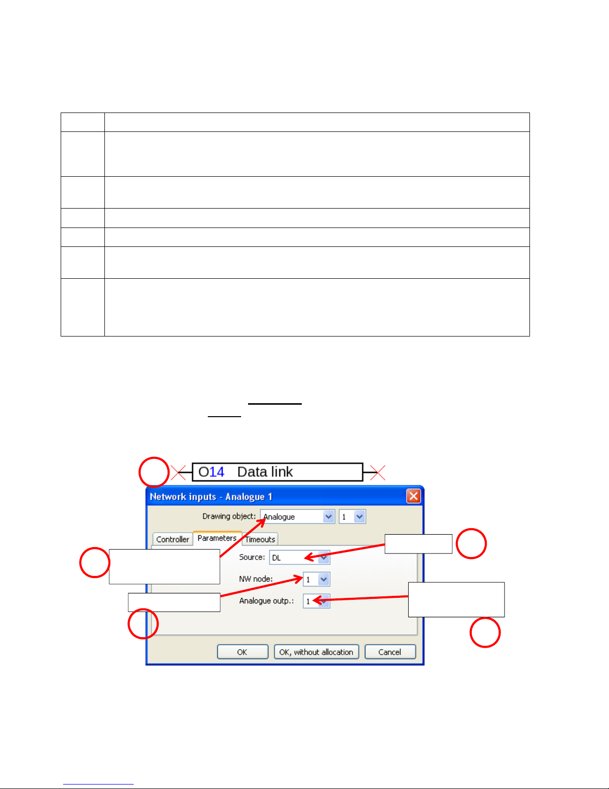
UVR1611:The measurements are parameterised as analog network inputs:
NW.Node: Sensor address
Anal.NW.Outp.: Index of the measured value
Source: DL
TAPPS2 Programming UVR1611:
A still unused network input variable must be selected for each new value. The values of in-
dices 1 and 5 displayed at the network input do not correspond to the temperatures and are
only correctly displayed in the controller in the measured values overview and in the func-
tions.
Analog
network input
Source: DL
Sensor address Index of the
measured value
1
3
4
2
5
13
ESR21, ESR31, UVR61-3, UVR63 and UVR63-H:
Adjustment of the measurements takes place in the menu EXT DL (external sensors)
Example: The external sensor 1 has address 1, the measured room tem-
perature is imported without offset values (index 2).
In the controllers ESR31, UVR61-3, UVR63 and UVR63-H (version 5.0 up
to 7.1), only the measured room temperature can be evaluated without off-
set values (index 2); the slider switch and the rotary knob have no purpose for these control-
lers. This value can subsequently be allocated to a sensor value (menu ENTER/Men – SEN-
SOR).
The room humidity value (only RAS-PLUS/F) is indicated in these controllers as a dimension-
less value without a decimal point (e.g. 35.5% -> Controller display: 355).
The values of indices 1 and 5 would be indicated with "999 and therefore cannot be used.
The menu option "EXT DL" is only available in the following controllers:
UVR 63-H from version 5.0
UVR 63 from version 1.0
UVR 61-3 from version 5.0
ESR 31 from version 1.0
ESR 21 from version 5.0
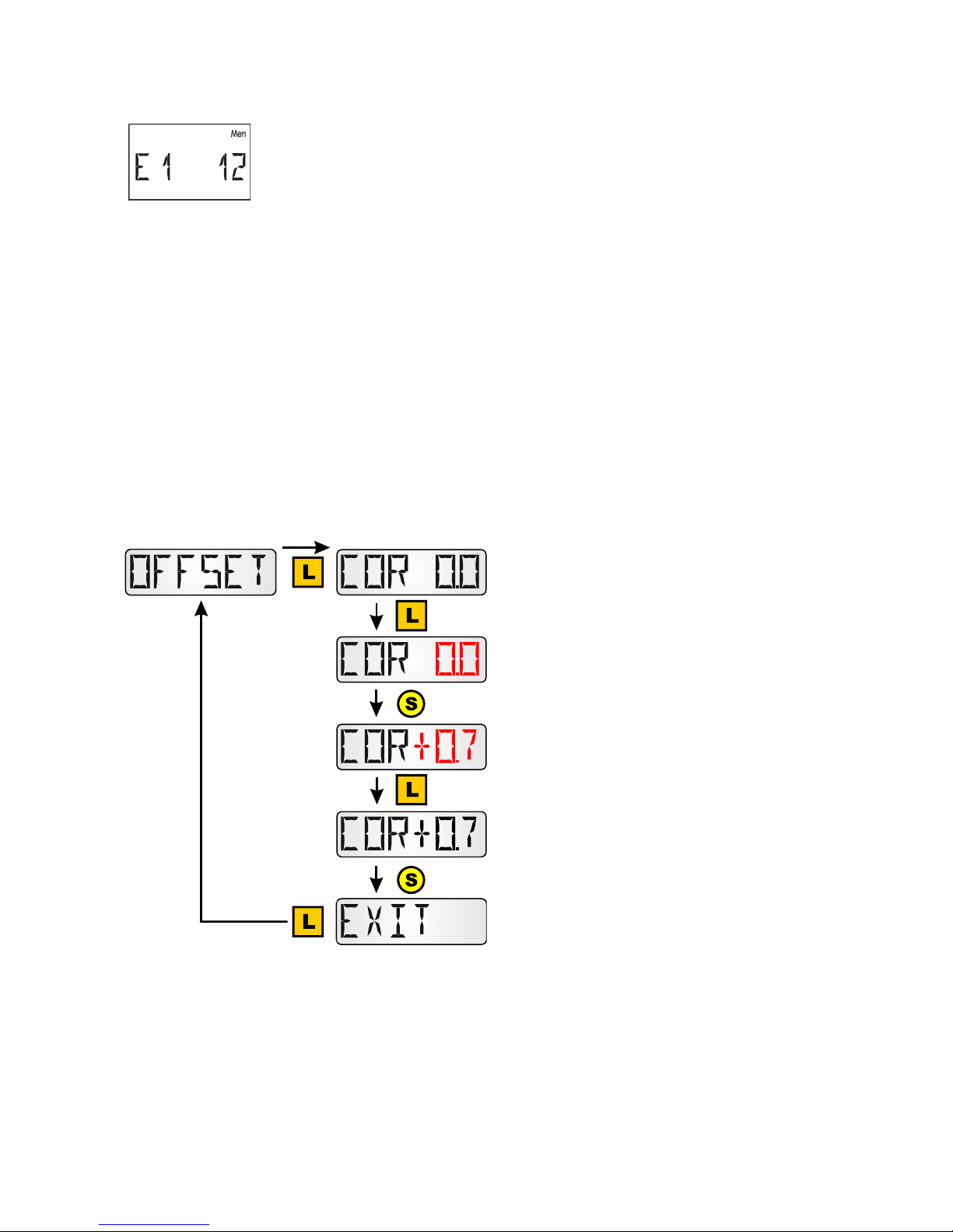
Entry of an offset value for sensor correction OFFSET
Entry COR 0.0 = no offset value selected,
therefore no sensor correction
Factory setting: COR 0.0
After a long key press "0.0" flashes
Selection of the desired offset value by
a short key press.
Confirmation of the desired value by a long
key press.
Entry COR +0.7 = The room temperature
value displayed and transmitted to the con-
troller is increased by 0.7 K.
Adjustment range: - 5.0K to +5.0K
Example: If there is an offset value of 0.7K and a measured temperature of 21.0°C, 21.7°C is
indicated (index value 1 and 2). This corrected value is used in the sequence for all calcula-
tions and forwarded to the controller.
Amongst those controllers that have no bidirectional data link (e.g. HZR65), i.e. amongst
those for which the RAS-PLUS can only be used as a remote display, this menu option is
still displayed but has no effective function and must therefore not be observed.
14
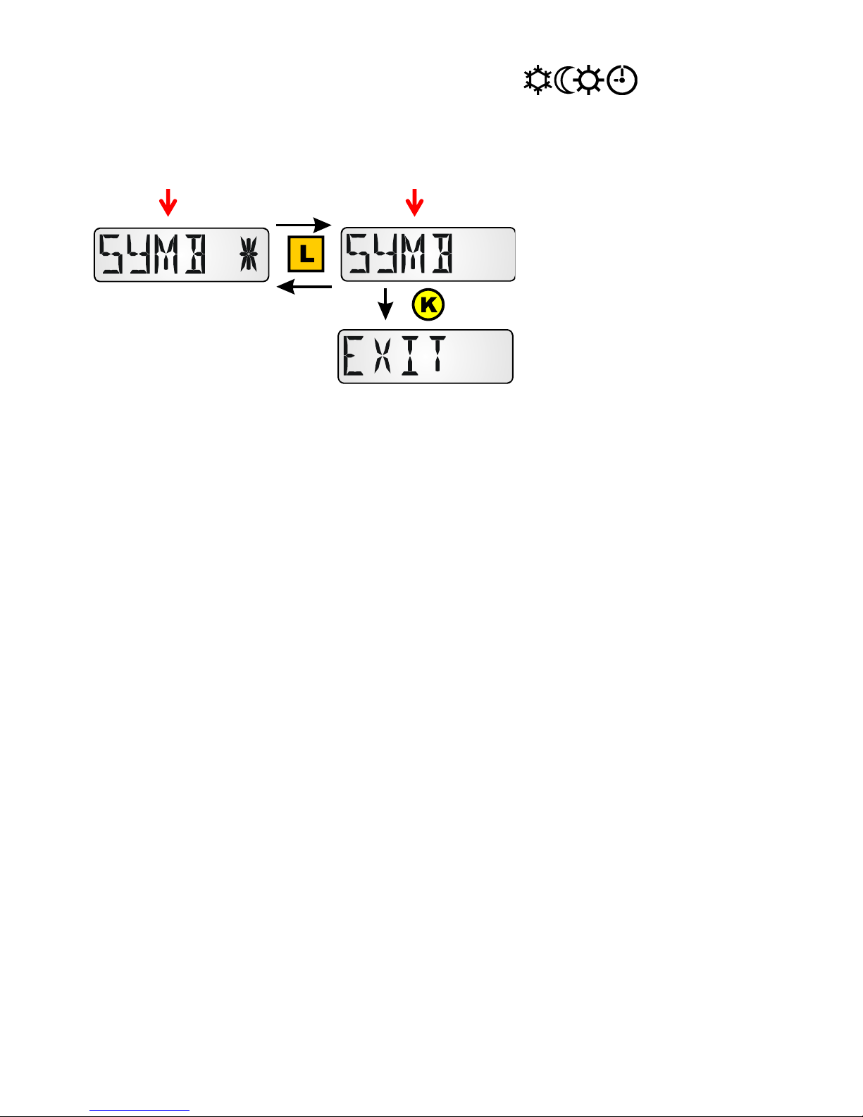
Display of operating mode symbols SYMB
In this menu, you can hide the symbols for the operating mode.
With symbols Without symbols
Press and hold the button for a
long time to select the required
display.

15
Menu VALUES
This is where the display is selected:
Sensor values SENSOR
Output statuses OUTPUT
Speed stages SPEED (only UVR16x2, RSM610, CAN-I/O45 and UVR 1611)
Heat quantity counter POWER (only for controllers with a heat quantity counter)
External sensors NETW (only ESR31 and ESR21 from version. 5)
Analog network inputs ANALNW (only UVR1611)
Digital network inputs DIGINW (only UVR1611)
Symbol allocation SYMB
Menu sensor values SENSOR
Access the menu by a long key press.
Selection by a long key press by the sensor
in question. The selection is indicated by
a star.
Depending on the controller type, up to 16
sensor values can be displayed.
Display examples:
Sensor 1 has an actual measured value of 94.1 °C.
For values from sensors that are not temperature sensors, no units are
displayed.
Input values for inputs that are not parameterised are shown with dash-
es.
Digital inputs are shown with "ON" or "OFF".

16
Menu output statuses OUTPUT
Access the menu by a long key press.
Selection by a long key press on the rele-
vant output. The selection is indicated by
a star.
Depending on the controller type, up to
14 output statuses can be displayed.
Analogue outputs 15 and 16 of controllers
UVR16x2 and UVR1611 cannot be dis-
played.
The output statuses of outputs 12 – 14 of
controller UVR16x2 are displayed correctly
only if they are defined as switching out-
puts.
Display example:
Output O1 is switched off.
If with the heating controller UVR63-H the outputs O2 and O3 are used for actuation of the
mixer motor, then the display for these outputs always remains on "OFF".
For the controllers UVR61-3, UVR63, UVR63-H, ESR21 and ESR31
after display of the outputs the speed stage of the adjustable outputs
can be displayed.
For controllers UVR61-3, UVR63, UVR63-H and ESR31 after display
of the speed stage, the value of control output 1 (ANL1) can be dis-
played.
17
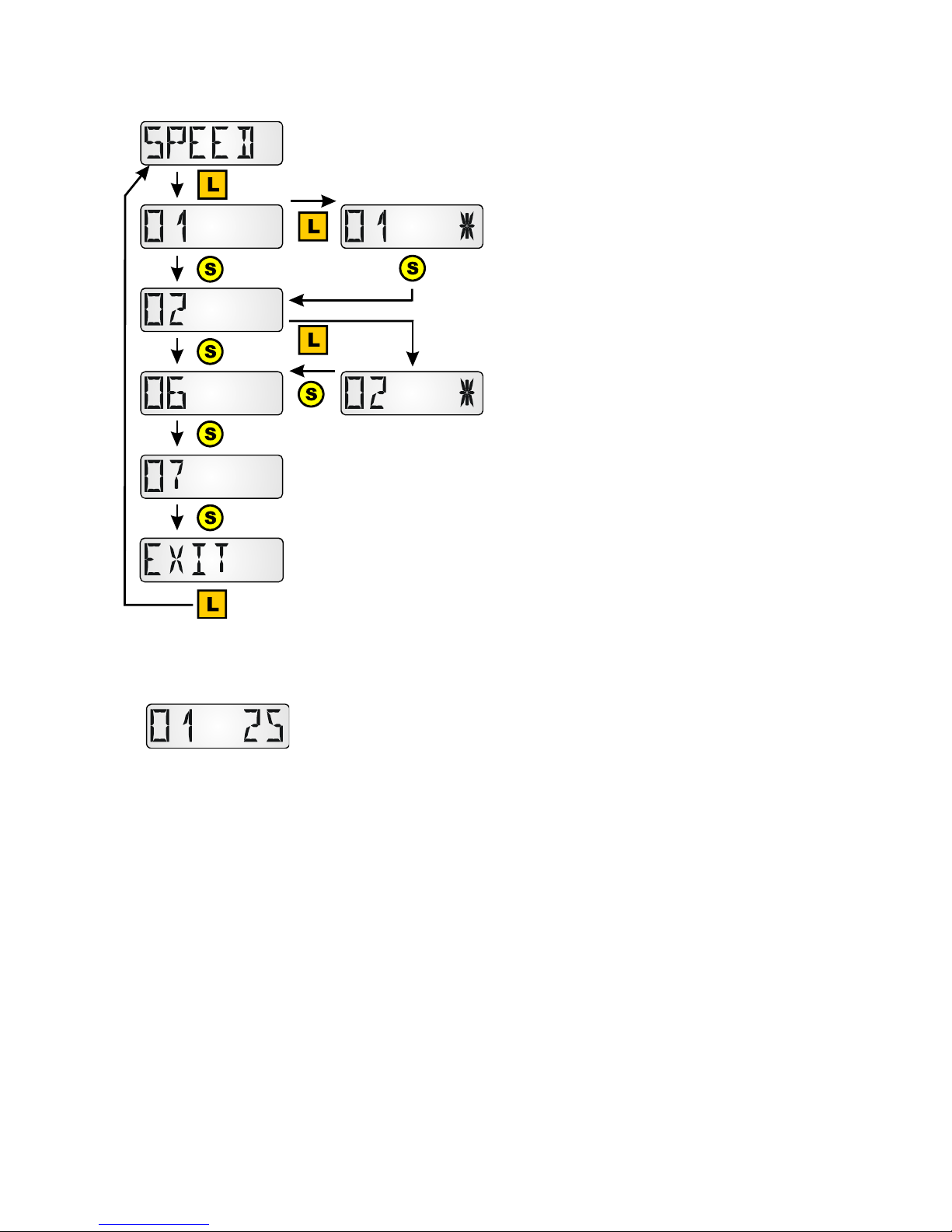
Menu speed stages SPEED (only UVR1611)
Access the menu by a long key press.
Selection by a long key press on the rele-
vant output. The selection is indicated by
a star. The speed of this output is displayed
after all the other displays have been dis-
played.
Display example:
The speed stage of output 1 is 25.

18
Menu heat quantity counter POWER
This menu option is only displayed for controllers with a heat quantity counter.
Access the menu by a long key press.
Selection through a long key press of the
value in question of the relevant heat quan-
tity counter The selection is indicated by
a star.
P1...4 = actual output in kW
KW1...4 = metered heat quantity in kWh
Once 999 kWh is reached, the
counter resets to 0 and the MWh
display is increased by 1.
MW1...4 = metered heat quantity in MWh
(1...4 = Number of the heat quantity coun-
ter, for controllers UVR16x2 and UVR1611
in the programming sequence)
Display examples:
Actual output of the heat quantity counter 1 in kW. For 4 character dis-
plays, "P1" flashes alternately with the value "17.28".
Metered heat quantity of the heat quantity counter 1 in kWh. For
3 character displays, "KW1" flashes alternately with the value "385".
Metered heat quantity of the heat quantity counter 1 in MWh.
19
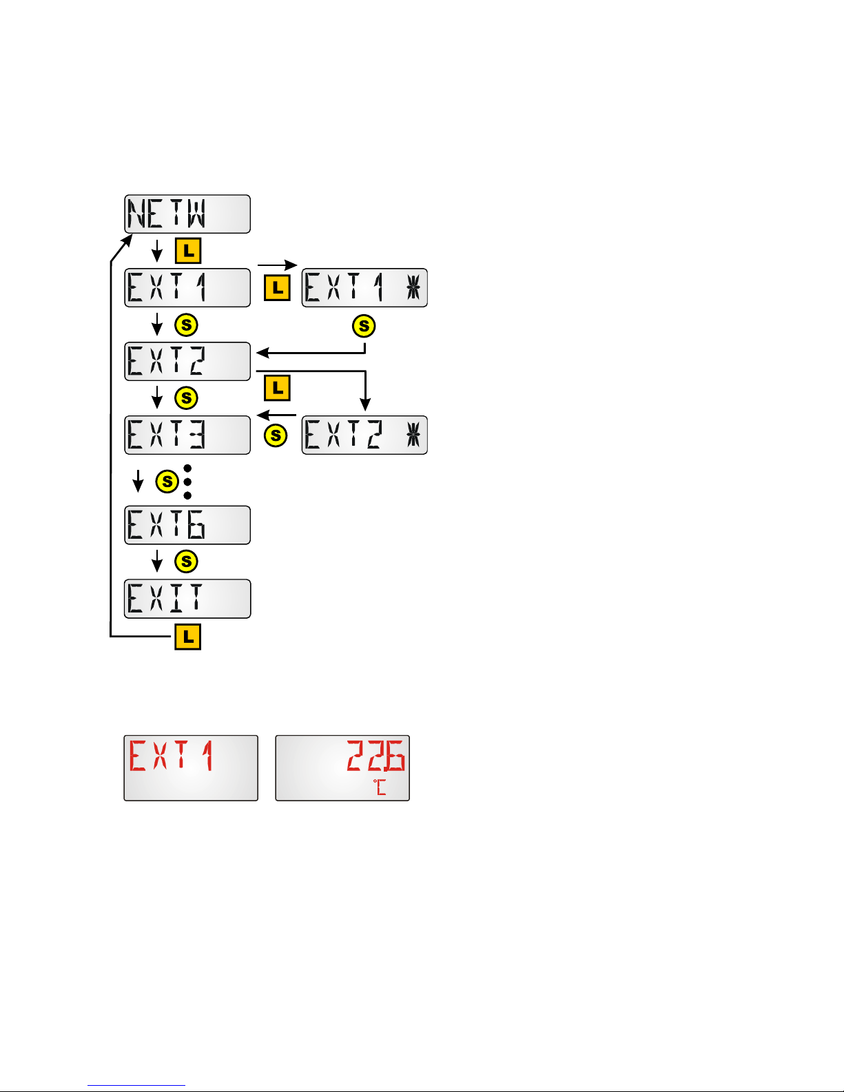
Menu external sensors NETW (only ESR21 (from version 5.0),
ESR31, UVR61-3 (from version 8.3), UVR63 (from version 1.5))
This selection is only possible for the above listed controllers, as only these controllers can
display external sensors across the data link.
Access the menu by a long key press.
Selection by a long key press by the rele-
vant external sensor. The selection is indi-
cated by a star.
Up to 6 external sensors can be displayed.
Display example:
Temperature display at the external sensor 1,
"EXT1" and "22.6°C" flash alternatively.
20
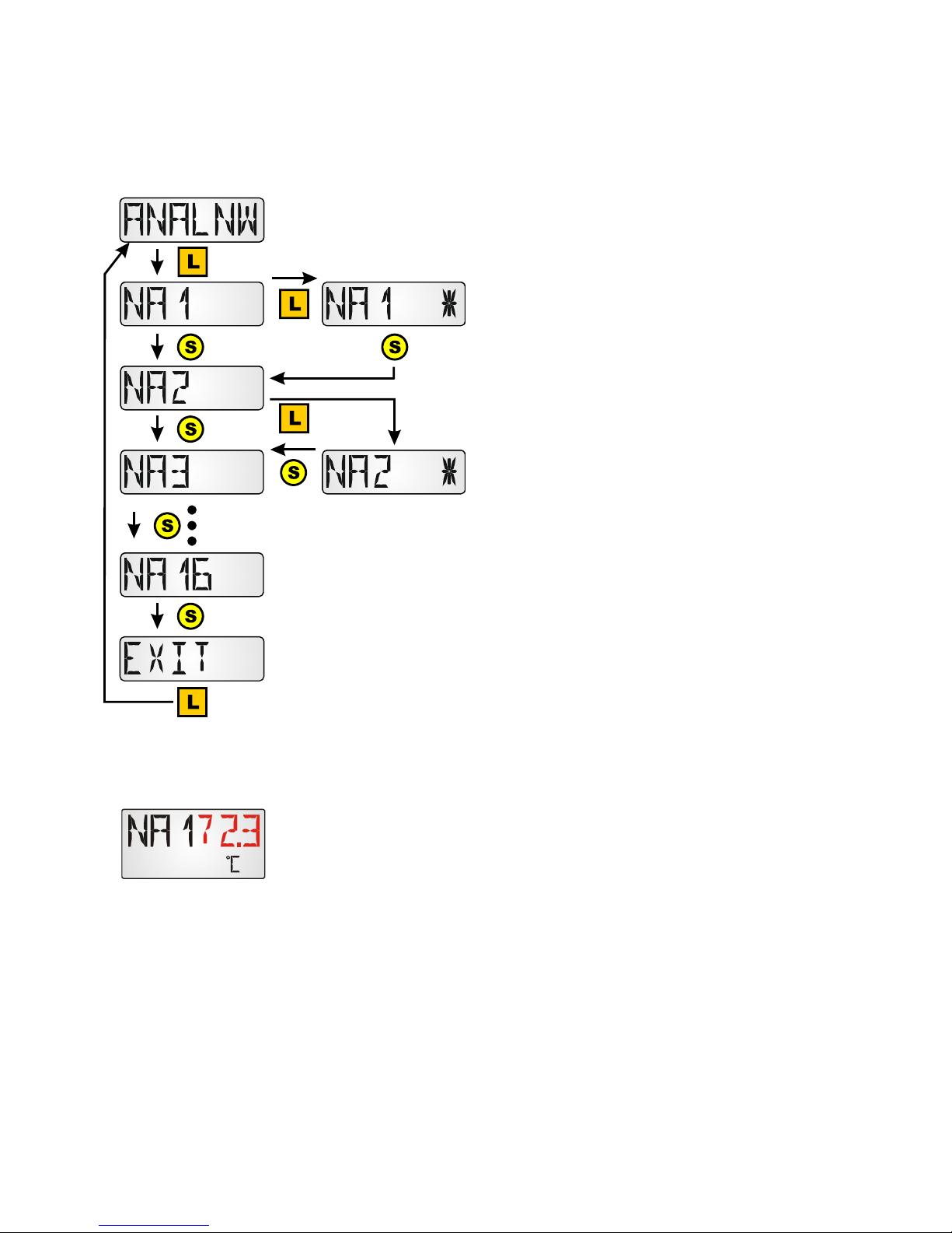
Menu analog CAN network inputs ANALNW (only UVR1611)
This selection is only possible for the controller UVR1611 as other controllers do not have
any CAN network. For output 14, the query NETW.IP.=>DL.: must be set to "yes".
Access the menu by a long key press.
Selection through a long key press by the
relevant analog network input. The selec-
tion is indicated by a star.
Up to 16 analog network inputs can be dis-
played.
Display example:
Actual value of the analog network input 1. For 3 character displays,
"NA1" flashes alternately with the value "72.3".
This manual suits for next models
1
Table of contents
Other Technische Alternative Accessories manuals


