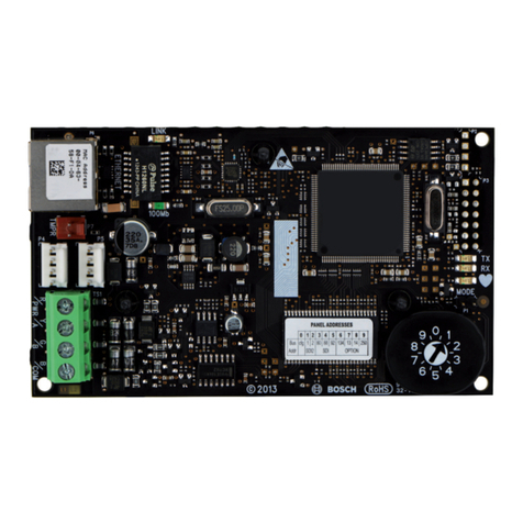
Technische Alternative RSM610-MB Manual


3
Table of contents
Safety requirements . . . . . . . . . . . . . . . . . . . . . . . . . . . . . . . . . . . . . . . . . . . . . . . . . . . . . . . . . . . 4
Maintenance . . . . . . . . . . . . . . . . . . . . . . . . . . . . . . . . . . . . . . . . . . . . . . . . . . . . . . . . . . . . . . . . . . . . . . . . . . .4
Disposal . . . . . . . . . . . . . . . . . . . . . . . . . . . . . . . . . . . . . . . . . . . . . . . . . . . . . . . . . . . . . . . . . . . . . . . . . . . . . .4
Standard delivery . . . . . . . . . . . . . . . . . . . . . . . . . . . . . . . . . . . . . . . . . . . . . . . . . . . . . . . . . . . . . . 5
Installing the device . . . . . . . . . . . . . . . . . . . . . . . . . . . . . . . . . . . . . . . . . . . . . . . . . . . . . . . . . . . 5
Opening the module . . . . . . . . . . . . . . . . . . . . . . . . . . . . . . . . . . . . . . . . . . . . . . . . . . . . . . . . . . . . . . . . . . . . .5
Mounting dimensions . . . . . . . . . . . . . . . . . . . . . . . . . . . . . . . . . . . . . . . . . . . . . . . . . . . . . . . . . . . . . . . . . . . .5
Dimensions drawing of enclosure . . . . . . . . . . . . . . . . . . . . . . . . . . . . . . . . . . . . . . . . . . . . . . . . . . . . . . . .6
Sensor installation . . . . . . . . . . . . . . . . . . . . . . . . . . . . . . . . . . . . . . . . . . . . . . . . . . . . . . . . . . . . . 7
Electrical connection . . . . . . . . . . . . . . . . . . . . . . . . . . . . . . . . . . . . . . . . . . . . . . . . . . . . . . . . . . . 8
Terminal diagram . . . . . . . . . . . . . . . . . . . . . . . . . . . . . . . . . . . . . . . . . . . . . . . . . . . . . . . . . . . . . . . . . . . . . . .9
Mains connection . . . . . . . . . . . . . . . . . . . . . . . . . . . . . . . . . . . . . . . . . . . . . . . . . . . . . . . . . . . . . . . . . . . . . . .9
Sensor leads . . . . . . . . . . . . . . . . . . . . . . . . . . . . . . . . . . . . . . . . . . . . . . . . . . . . . . . . . . . . . . . . . . . . . . . . . .10
Sensor terminal diagram . . . . . . . . . . . . . . . . . . . . . . . . . . . . . . . . . . . . . . . . . . . . . . . . . . . . . . . . . . . . . .10
Data cable for DL bus . . . . . . . . . . . . . . . . . . . . . . . . . . . . . . . . . . . . . . . . . . . . . . . . . . . . . . . . . . . . . . . . . . .11
Terminal diagram, DL bus data cable . . . . . . . . . . . . . . . . . . . . . . . . . . . . . . . . . . . . . . . . . . . . . . . . . . . .11
Bus load of DL sensors . . . . . . . . . . . . . . . . . . . . . . . . . . . . . . . . . . . . . . . . . . . . . . . . . . . . . . . . . . . . . . .11
CAN Bus network . . . . . . . . . . . . . . . . . . . . . . . . . . . . . . . . . . . . . . . . . . . . . . . . . . . . . . . . . . . . . . . . . . . . . .12
Terminal diagram, CAN bus cable . . . . . . . . . . . . . . . . . . . . . . . . . . . . . . . . . . . . . . . . . . . . . . . . . . . . . . .12
Guidelines for the topology of a CAN network . . . . . . . . . . . . . . . . . . . . . . . . . . . . . . . . . . . . . . . . . . . . .12
Technical principles . . . . . . . . . . . . . . . . . . . . . . . . . . . . . . . . . . . . . . . . . . . . . . . . . . . . . . . . . . . . . . .12
Lightning protection . . . . . . . . . . . . . . . . . . . . . . . . . . . . . . . . . . . . . . . . . . . . . . . . . . . . . . . . . . . . . . .13
Examples of different network versions . . . . . . . . . . . . . . . . . . . . . . . . . . . . . . . . . . . . . . . . . . . . . . .13
Cable selection and network topology . . . . . . . . . . . . . . . . . . . . . . . . . . . . . . . . . . . . . . . . . . . . . . . . . . .15
Outputs . . . . . . . . . . . . . . . . . . . . . . . . . . . . . . . . . . . . . . . . . . . . . . . . . . . . . . . . . . . . . . . . . . . . . . . . . . . . . .18
Terminal diagram, switching outputs . . . . . . . . . . . . . . . . . . . . . . . . . . . . . . . . . . . . . . . . . . . . . . . . . . . .18
Terminal diagram for analogue outputs (0-10V / PWM) . . . . . . . . . . . . . . . . . . . . . . . . . . . . . . . . . . . . . .19
Connection auxiliary relay HIREL-230V . . . . . . . . . . . . . . . . . . . . . . . . . . . . . . . . . . . . . . . . . . . . . . . . . . .20
HIREL-230V wiring diagram . . . . . . . . . . . . . . . . . . . . . . . . . . . . . . . . . . . . . . . . . . . . . . . . . . . . . . . . .20
Technical data RSM610 . . . . . . . . . . . . . . . . . . . . . . . . . . . . . . . . . . . . . . . . . . . . . . . . . . . . . . . . 21
Tips on troubleshooting . . . . . . . . . . . . . . . . . . . . . . . . . . . . . . . . . . . . . . . . . . . . . . . . . . . . . . . . 22
Technical support . . . . . . . . . . . . . . . . . . . . . . . . . . . . . . . . . . . . . . . . . . . . . . . . . . . . . . . . . . . . . . . . . . . . . .22
Troubleshooting in the CAN network . . . . . . . . . . . . . . . . . . . . . . . . . . . . . . . . . . . . . . . . . . . . . . . . . . . . . . .24
Information on the ECO-design Directive 2009/125/EC . . . . . . . . . . . . . . . . . . . . . . . . . . . . . . . . . . . . . . . . .24
User manual . . . . . . . . . . . . . . . . . . . . . . . . . . . . . . . . . . . . . . . . . . . . . . . . . . . . . . . . . . . . . . . . 26
LED status indicators . . . . . . . . . . . . . . . . . . . . . . . . . . . . . . . . . . . . . . . . . . . . . . . . . . . . . . . . . . . . . . . . . . .26
Status indicators at controller start . . . . . . . . . . . . . . . . . . . . . . . . . . . . . . . . . . . . . . . . . . . . . . . . . . . . .26
Operation via UVR16x2 or CAN-MTx2 . . . . . . . . . . . . . . . . . . . . . . . . . . . . . . . . . . . . . . . . . . . . . . . . . . . . . .27
User levels . . . . . . . . . . . . . . . . . . . . . . . . . . . . . . . . . . . . . . . . . . . . . . . . . . . . . . . . . . . . . . . . . . . . . . . . .27
Information displayed on the controller . . . . . . . . . . . . . . . . . . . . . . . . . . . . . . . . . . . . . . . . . . . . . . . . . .28
Main menu display . . . . . . . . . . . . . . . . . . . . . . . . . . . . . . . . . . . . . . . . . . . . . . . . . . . . . . . . . . . . . . . .29
Function overview display . . . . . . . . . . . . . . . . . . . . . . . . . . . . . . . . . . . . . . . . . . . . . . . . . . . . . . . . . .30
Status line . . . . . . . . . . . . . . . . . . . . . . . . . . . . . . . . . . . . . . . . . . . . . . . . . . . . . . . . . . . . . . . . . . . . . .34
Function overview . . . . . . . . . . . . . . . . . . . . . . . . . . . . . . . . . . . . . . . . . . . . . . . . . . . . . . . . . . . . . . . . . . .36
Changing values . . . . . . . . . . . . . . . . . . . . . . . . . . . . . . . . . . . . . . . . . . . . . . . . . . . . . . . . . . . . . . . . . .37
The most important functions . . . . . . . . . . . . . . . . . . . . . . . . . . . . . . . . . . . . . . . . . . . . . . . . . . . . . . .39
Messages . . . . . . . . . . . . . . . . . . . . . . . . . . . . . . . . . . . . . . . . . . . . . . . . . . . . . . . . . . . . . . . . . . . . . . . . .47
Sensor and bus errors . . . . . . . . . . . . . . . . . . . . . . . . . . . . . . . . . . . . . . . . . . . . . . . . . . . . . . . . . . . . .47
Operation via C.M.I. . . . . . . . . . . . . . . . . . . . . . . . . . . . . . . . . . . . . . . . . . . . . . . . . . . . . . . . . . . . . . . . . . . . .48
Changing a value . . . . . . . . . . . . . . . . . . . . . . . . . . . . . . . . . . . . . . . . . . . . . . . . . . . . . . . . . . . . . . . . . . . .49
Manual Version 1.26

4
Safety requirements
This device is state of the art and meets all necessary safety regulations. It may only be used
in accordance with the technical data and the safety requirements and regulations listed be-
low. When using the device, also observe the statutory and safety regulations apposite to
the particular use. Any other use will automatically void all warranty rights.
• The device must only be installed in a dry interior room.
• It must be possible to isolate the controller from the mains using an omnipolar isolating
facility (plug/socket or 2-pole isolator).
• Before starting installation or wiring work, the controller must be completely isolated
from the mains and protected against reconnection. Never interchange the safety low
voltage connections (e.g. sensor connections) with the 230 V connections. Destruction
and life threatening voltages at the device and the connected sensors may occur.
• Solar thermal systems can become very hot. Consequently there is a risk of burns. Pro-
ceed with caution when fitting temperature sensors.
• For safety reasons, the outputs should only be left in manual mode when testing. In this
operating mode, no maximum temperatures or sensor functions are monitored.
• Safe operation is no longer possible if the controller or connected equipment exhibits
visual damage, no longer functions or has been stored for lengthy periods in unsuitable
conditions. If this is the case, disable the controller and equipment and secure against
unintentional use.
Maintenance
If treated and used correctly, the device will not require any maintenance. Use a cloth mois-
tened with mild alcohol (such as methylated spirits) to clean. Never use corrosive cleaning
agents or solvents such as chloroethylene or trichloroethylene.
No components relevant to long term accuracy are subject to loading if the device is used
correctly. Consequently long term drift is extremely low. The device therefore cannot be cal-
ibrated. Thus applying any compensation is impossible.
The design characteristics of the device must not be changed during repairs. Spare parts
must correspond to the original spare parts and must be used in accordance with the build
version.
Disposal
• Devices no longer in use or beyond a state of repair must be disposed of
in an environmentally responsible manner by an authorised collection point.
They mus never be treated as ordinary household waste.
• We can undertake the environmentally responsible disposal of devices
sold by the Technischen Alternative company upon request.
• Packaging material must be disposed of in an environmentally responsible
manner.
• Incorrect disposal may result in considerable damage to the environment,
as many of the materials used require professional handling.
All installation and wiring work on the controller must only be carried out
in a zero volt state. The opening, connection and commissioning of the
device may only be carried out by competent personnel. While doing so,
they must observe all local safety requirements.

5
Standard delivery
• RSM610 control module
• Power cable 12 / 0.75 m with earthed plug
• Installation instructions
• Accessories
• Installation material
• Enclosure lock
• Locking clamp with strain relief
Installing the device
Opening the module
Unscrew the screws on the front and lift the cover.
The electronics are located in the cover. The connection to the terminals in the lower section of the
enclosure is made by contact pins when the cover is put in place.
The lower section can be wall mounted through the slots provided (with the cable entries in the side
facing down) or mounted on a top-hat rail (TS35 support rail as defined by the EN50022 standard).
Mounting dimensions
CAUTION: Always pull the mains plug before opening the enclosure!
Only work inside the module when the power supply is at zero volt.

6
Dimensions drawing of enclosure

7
Sensor installation
Correct arrangement and installation of the sensors is extremely important for correct functioning
of the system. To this end, also ensure that they are completely inserted in their sensor wells. The
cable fittings provided serve as strain relief. When used outdoors, no water must be allowed to
penetrate the sensor wells (risk of frost). The contact sensors must be insulated well to protect
them from being influenced by the ambient temperature.
Fundamentally, sensors should not be exposed to moisture (such as condensation) since this can
diffuse through the cast resin and damage the sensor. If this happens, heating the sensor to 90 °C
for an hour may help. When using sensor wells in stainless steel cylinders or swimming pools,
particular attention must be given to their corrosion resistance.
•Collector sensor (grey lead with junction box): Either insert into a pipe which is brazed
or riveted directly to the absorber and protrudes from the collector housing, or insert a
tee into the flow manifold of the outermost collector into which the sensor well, together
with the brass cable fitting (= protection against moisture), can be inserted; then insert
the sensor. To protect against lightning damage, the junction box has a surge protection
(voltage dependent resistor) which is clamped in parallel between the sensor and the
extension cable.
•Boiler sensor (boiler flow): This sensor is either inserted into a sensor well in the boiler
or fitted to the flow line as close to the boiler as possible.
•DHW cylinder sensor: The sensor required for the solar thermal system should be used
with a sensor well for finned tube heat exchangers just above the exchanger or, if inte-
grated smooth tube heat exchangers are used, in the lower third of the exchanger or the
exchanger’s return outlet so that the sensor well protrudes into the heat exchanger tube.
The sensor monitoring the heating of the DHW cylinder by the boiler is installed at a level
corresponding to the amount of domestic hot water required during the heating season.
The supplied cable fitting acts as strain relief. Installation below the associated coil or
heat exchanger is not permissible under any circumstances.
•Buffer sensor: The sensor required for the solar thermal system is fitted in the lower sec-
tion of the cylinder just above the solar indirect coil using the sensor well supplied. The
supplied cable fitting acts as strain relief. As the reference sensor for the heating system
hydraulics, it is recommended to insert the sensor into the sensor well between the cen-
tre and upper third of the buffer cylinder, or positioned against the cylinder wall under-
neath the insulation.
•Pool sensor (swimming pool): Fit a tee into the suction line immediately on the pool out-
let and insert the sensor with a sensor well. In the process, ensure the material used is
corrosion-resistant. A further option would be to fit the sensor as a contact sensor with
appropriate thermal insulation against ambient influences.
•Contact sensor: Use scroll springs, pipe clips, etc. to attach the contact sensor to the
respective line. Ensure the material used is suitable (corrosion, temperature resistance,
etc.). Then insulate the sensor thoroughly so that the pipe temperature is captured accu-
rately and ambient temperatures cannot falsify the result.
•DHW sensor: A rapid reaction to changes in the water volume is extremely important
when using the controller in systems that generate domestic hot water by means of an
external heat exchanger and variable speed pump (freshwater module). Therefore fit the
DHW sensor directly on the heat exchanger outlet. This ultra-quick sensor (special
accessory, type MSP ...) should protrude into the output with the aid of a tee sealed in
with an O-ring. The heat exchanger should be installed upright with the DHW outlet at the
top.

8
•Radiation sensor: The parallel collector orientation is important in order to obtain a mea-
surement that corresponds to the collector position. Consequently it should be secured
to the sheet steel covering or adjacent to the collector on an extension of the mounting
rail. To this end, the sensor casing has a blind hole that can be opened at any time. The
sensor is also available as a wireless version.
•Room sensor: This sensor is intended for installation in the living space (reference
room). Do not install the room sensor near a heat source or window. By simply replug-
ging a jumper inside the sensor, each room sensor can also be used exclusively as a
remote adjuster (no room temperature influence). It is only suitable for operation in dry
rooms. The sensor is also available as a wireless version.
•Outside temperature sensor: This sensor is installed on the coldest wall (usually facing
north) some two meters above the ground. Avoid temperature influences from nearby air
shafts, open windows, cable ways, etc. It must not be subjected to direct insolation.
Electrical connection
This must only be carried out by a qualified electrician in accordance with the relevant local
regulations.
Note: In line with regulations, the system must be equipped with protection against lightning
(surge arrester). Sensor failures due to thunderstorms and static electricity are usually the
result of missing or incorrect earthing or missing surge protection.
Caution: Only work inside the module when the power supply is at zero volt. Assembling the
device with the power connected may result in damage.
Connect all sensors and pumps/valves as they are numbered in the respective program.
In the mains voltage range, fine wire cross-sections of 0.75 - 1.5 mm² are recommended, ex-
cept for the supply cable.
A terminal strip is provided in the 230 V terminal box for connection of the earth conductor
(PE). All cables can be fixed with a locking clamp (= strain relief) immediately after termina-
tion. Subsequently, side cutters are required to remove the locking clamps; therefore, more
clamps than necessary are provided.

9
Terminal diagram
View of the lower enclosure section with terminals:
Mains connection
Power is supplied through a power supply unit integrated into the module. The mains connection
must therefore be 230 V 50 Hz. This is also the voltage conducted by the output relay. The integral
power supply unit also supplies power to the CAN bus.

10
Sensor leads
Sensor terminal diagram
Sensors are always connected across the relevant sensor terminal (S1 – S6) and sensor earth (GND).
There is an earth strip in the base. A connection to the GND terminal must be laid using this strip be-
fore the sensors are connected.
In order to prevent measurement fluctuations and ensure perfect signal transmission, sensor leads
must not be subject to external negative influences through 230 V cables.
Never run sensor leads together with mains voltage cables in the same conduit.
When using non-screened cables, route sensor leads and 230 V cables either in separate cable con-
duits or with a minimum clearance of 5 cm.
Sensor leads for PT100 or PT500 sensors must be screened.
If screened cables are used, the screen must be connected to the sensor earth (GND)
All sensor leads with a cross-section of 0.5 mm2 can be extended to up to 50 metres. With this lead
length and a PT1000 temperature sensor, the measuring error is approximately +1 K. A correspond-
ingly larger cross-section is required for longer leads or a lesser measuring error.
The connection between the sensor and the extension can be made by pushing heat shrink tubing
(trimmed to 4 cm) over one core and twisting the bare wire ends. Solder the connection if one of the
wire ends has been tin-plated.
Then push the heat shrink tubing over the connection and heat up carefully (e.g. with a lighter) until
it sits tightly over the connection.

11
Data cable for DL bus
The DL BUS consists of just 2 wires: DL and GND (sensor earth). The DL BUS itself supplies the nec-
essary power for the DL BUS sensors.
Cables can be routed with a star topology but also in serial formation (from one device to the next).
Any cable with a cross-section of 0.75 mm², and measuring up to 30 m in length, can be used as a
data link. For lengths greater than 30 m, the use of screened cables is recommended, which increas-
es the reliable length of the cable to 100 m.
If screened cables are used, the screen must be connected to GND.
Long cable conduits routed closely next to each other for mains and data cables result in faults being
induced into the data cables from the mains. We therefore recommend a minimum clearance of
20 cm between two cable conduits or the use of screened cables.
Use separate, screened cables when capturing data from two controllers with a single datalogger.
Never run the data cable together with a CAN BUS cable in the same conduit.
Terminal diagram, DL bus data cable
Bus load of DL sensors
A 2-pole cable provides both the power supply and the signal transfer from DL BUS sensors. An ad-
ditional power supply by means of an external power supply unit (such as with the CAN BUS) is not
possible.
Take the "BUS load" into consideration as sensors have a relatively high current demand:
The RSM610 module supplies the total BUS load. The BUS loads of the electronic sensors are listed
in the technical data of the relevant sensors.
Example: The electronic sensor FTS4-50DL has a BUS load of 25 %. Consequently up to four FTS4-
50DL can be connected to the DL BUS.

12
CAN Bus network
Terminal diagram, CAN bus cable
Guidelines for the topology of a CAN network
Technical principles
The CAN BUS comprises the cables CAN-High,
CAN-Low, GND and one +12 V supply cable for
BUS components without their own power supply.
The combined total load of all devices with 12 V
and 24 V supply must not exceed 6 W.
Design CAN networks in a linear fashion and set a
terminator at each network termination. This is
ensured by the termination of the end devices.
In the case of larger networks (covering several
buildings), problems can occur through electro-
magnetic interference and potential differences.
To avoid or to the greatest extent manage such
problems, take the following measures:
• Cable screening
The BUS cable screen must be connected well at every node to provide continuity. For larger net-
works we recommend including the screen in the equipotential bonding, in line with the exam-
ples shown.
• Equipotential bonding
As low an ohm connection as possible to the earth potential is particularly important. Where
cables enter buildings, ensure that the cable entries are in the same location where possible and
that all are connected to the same equipotential bonding system (SingleEentryPoint principle). The
purpose is to create potentials that are as similar as possible, in order to achieve the smallest
possible potential difference to adjacent lines in case one line suffers a voltage surge (lightning
strike). Also ensure a corresponding clearance between the cable and lightning protection sys-
tems.
The equipotential bonding also has positive properties to counteract interferences emitted from
linked cables.

13
• Avoiding earth loops
Where a bus cable is routed between several buildings, ensure that earth loops are avoided. The
reason for this is that buildings actually have different potentials compared to the earth poten-
tial. An earth loop is created when connecting one cable screen in each building directly with the
equipotential bonding system. In other words, a current flows from the higher to the lower poten-
tial.
For example, if lightning strikes near one of the buildings, the potential of that building will briefly
be raised by several kV.
In this case, the equalizing current flows to earth via the bus screen and causes an extreme elec-
tromagnetic input which can result in the destruction of the bus components.
Lightning protection
Efficient lighting protection is highly dependent on good building earthing that meets the relevant
regulations.
An external lightning protection system offers protection against a direct lightning strike.
In order to protect against voltage surges in the 230 V mains supply cable (indirect lightning strike),
appropriate lightning conductors and surge arresters compliant with local regulations must be fitted
in the upstream distribution systems.
In order to protect the individual components of a CAN network against indirect lightning strike, we
recommend the use of surge arresters specifically developed for bus systems.
Example: CAN bus surge arresters CAN-UES from Technische Alternative
Gas discharge arrester for indirect earthing EPCOS N81-A90X
Examples of different network versions
Key to symbols:
„Small“ network (within one building):
Max. cable length: 1000 m at 50 kbit/s
The screen must be continued at each network node and be connected to the device earth (GND).
The screen earthing or GND must only be implemented indirectly via a gas discharge arrester.
Ensure that no unintentional direct connection of earth or screen and the earth potential is created
(e.g. via sensors and the earthed pipework).
… device with its own power supply (UVR16x2, UVR1611K, UVR1611S, UVR1611E)
… device is supplied by the bus (CAN I/O, CAN-MT, …)
… CAN-Repeater (CAN-RP)
… terminated (end devices) … open termination
… CAN bus surge arrester ... gas discharge arrester for indirect earthing

14
Network (across several buildings) without CAN-Repeater CAN-RP:
Max. cable length: 1000 m at 50 kbit/s
The screen must be continued at every network node and earthed at a single point, as close to the
cable center as possible. We recommend earthing the screen indirectly in the other buildings using
a gas discharge arrester. The screen is not connected with the earth (GND) of the devices.
Netzwerk (across several buildings) with CAN-Repeater CAN-RP:
Maximum cable length: subject to the set Baud rate
The screen of the disconnected network is connected at each bus converter to CAN bus earth (GND).
This screen must not be directly earthed.
Without CAN Bus surge arresters, this version only protects against potential differences up to 1 kV,
therefore cannot be considered as lightning protection. In this case, the cable screen must be
earthed at a single point between the CAN bus converters, as close to the cable centre as possible.
We recommend earthing the screen indirectly in the other buildings using a gas discharge arrester.
A CAN bus converter is similar to a repeater. It receives CAN bus signals and passes them on. Each
cable run on either side of the CAN bus converter must therefore be viewed as an independent CAN
bus network.

15
Cable selection and network topology
Screened twisted pairs have proven useful in CANopen networks. These are cables with twisted
pairs of conductors and a shared external screen. Such cables are relatively resistant to EMC inter-
ference and can still carry 50 kbit/s for up to 1000 m. The CANopen recommendations (CiA DR 303-
1) for cable cross-sections are given in the table below.
The maximum cable length also depends on the number of nodes [n] linked with the bus cable and
the cable cross-section [mm²].
Bus rate
In the CAN bus / CAN settings menu of the UVR16x2, the bus rate can be set to between 5 and
500 kbit/s, whereby lower bus rates enable longer cable networks. However, in this case, the cable
cross-section must be increased accordingly.
The standard bus rate of the CAN network is 50 kbit/s (50 kBaud), which is specified for many CAN
bus devices.
Important: All devices in the CAN bus network must have the same transfer rate in order to be
able to communicate with each other.
Recommendations
A 2x2-pole, screened twisted pair (twist CAN-L with CAN-H or +12 V with GND) with a cable cross-
section of at least 0.5 mm² and a conductor-to-conductor capacity of no more than 60 pF/m and a
nominal impedance of 120 ohms. The standard bus speed of the UVR16x2 is 50 kbit/s. This recom-
mendation corresponds, for example, to cable type Unitronic®-BUS CAN 2x2x0.5 supplied by Lapp
Kabel for permanent installation in buildings or conduits. Theoretically this would enable a bus
length of approx. 500 m to guarantee reliable transmission.
For direct routing underground, earth cable 2x2x0.5 mm² supplied by HELUKABEL, part no. 804269,
or earth cable 2x2x0.75 mm² supplied by Faber Kabel, part no. 101465, would be suitable.
Bus length
[m]
Resistance in terms of
length [mΩ/m]
Cross-section
[mm2]
0...40 70 0,25...0,34
40...300 < 60 0,34...0,60
300...600 < 40 0,50...0,60
600...1000 < 26 0,75...0,80
Cable cross-section
[mm2]
Maximum length [m]
n=32 n=63
0,25 200 170
0,50 360 310
0,75 550 470
Bus rate [kbit/s] Maximum permissible total bus length [m]
5 10.000
10 5.000
20 2.500
50 (standard) 1.000
125 400
250 200
500 100

16
Wiring
A CAN BUS network should never have a star topology. Rather, the correct topology is a line from the
first device (with terminator) to the second, third and so forth. The last bus device has the termina-
tion jumper again.
Example: Connection of three network nodes (NWN) with a 2x2-pole cable and termination of the ter-
minal network nodes (network inside one building)
Each CAN network is to be provided with a 120 ohm BUS terminator at the first and last network sub-
scriber (= termination). This is achieved with a plug-in jumper at the back of the controller. Each CAN
network therefore always has two terminators (one at each end). Branch cables or a star topology
are not permissible for CAN wiring.

17
Branch cables
A CAN bus converter is used to provide reliable long branch cables. This means the branch cable is
disconnected from the other CAN bus network and can be viewed as an independent CAN bus net-
work.
Trials at the factory have shown the following:
1) Branches with a star topology of up to 10 m will not impede transmission.
2) Up to a bus length of 250 m and a transfer rate of 50 kbit/s, data transfer works perfectly with a
low number of CAN nodes and an inexpensive J-Y(St)Y EIB KNX 2x2x0.8 KNX bus cable with a char-
acteristic impedance of 75 to 90 ohm.
3) Up to a bus length of 150 m and with only a few nodes, the CAT 5 24AWG cable (typical Ethernet
cable in PC networks) can be used.
Changing to cable types with different characteristic impedances is only permitted via signal sepa-
ration through a CAN bus converter.
However, such networks do not comply with the recommended specification. Technische Alternative
RT GmbH therefore cannot guarantee trouble-free operation if one of the three options listed above
is applied.

18
Outputs
Terminal diagram, switching outputs
For maximum current load of the outputs, see the technical data.
Potential-free connection of output 6
By unplugging jumper J, output A6 can be rendered potential-free.
View of module back:
With jumper J plugged in, output 6 is not po-
tential-free.
Example: Connecting a pump
C (= L).... Phase conductor
A6.... Normally open contact (N/O)
NC.... Normally closed contact (N/C)
If the jumper is unplugged, output 6 is poten-
tial-free.
Example: Burner demand
C.... Root C
A6.... Normally open contact (N/O)
NC.... Normally closed contact (N/C)

19
Terminal diagram for analogue outputs (0-10V / PWM)
The connections A7-A10 are the positive pole; the GND connection is the negative pole.
When programmed as the "switching output", up to 2 HIREL-230V or HIREL-PF auxiliary relays can be
connected.

20
Connection auxiliary relay HIREL-230V
Example: Connection HIREL16x2 for analogue outputs A7 and A8.
Program outputs A7 and A8 as switching outputs.
The auxiliary relay cannot be integrated in the module; it requires its own enclosure.
HIREL-230V wiring diagram
Both relay outputs are protected by the fuse on the relay module. Terminal "W" therefore corresponds
to phase conductor "L".
If the fuse is removed, both outputs will be potential-free whilst remaining connected to one another
via root "W".
The relay module can be connected to any two outputs between A7 and A10 if these have been pro-
grammed as switching outputs.
This manual suits for next models
3
Table of contents
Other Technische Alternative Control Unit manuals
Technische Alternative
Technische Alternative ESR 31 User manual
Technische Alternative
Technische Alternative ESR 21 Series User manual
Technische Alternative
Technische Alternative ANS 21 User manual
Technische Alternative
Technische Alternative CAN-I/O45 User manual

Technische Alternative
Technische Alternative ESR 31 User manual

