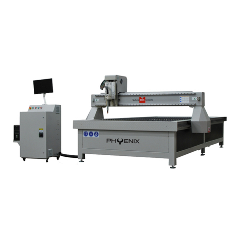
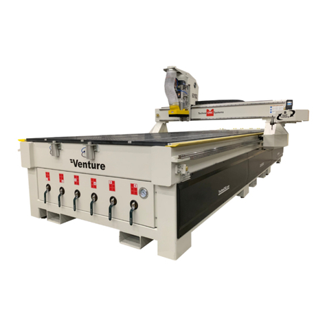
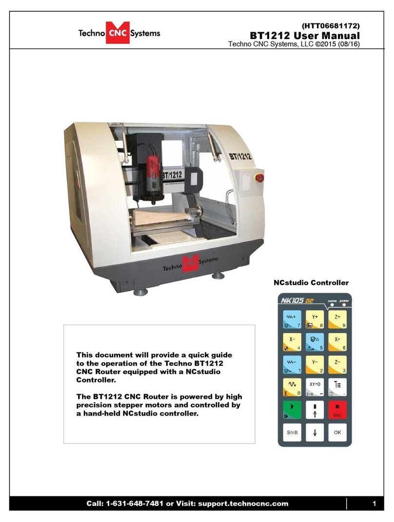
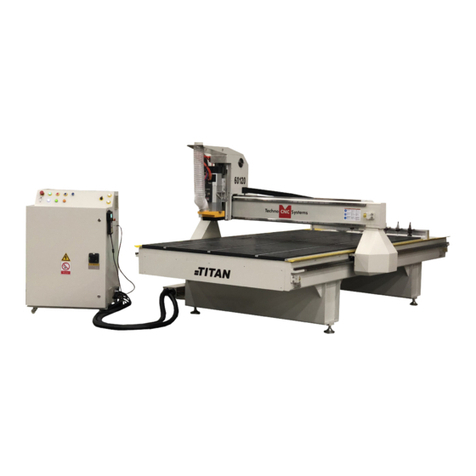
Techno CNC Systems HD series User manual

Call: 1-631-648-7481 or Visit: support.technocnc.com 1
HD WinCNC Manual
(HTT0674)
This document will provide a quick guide to the set up and operating
procedure of the Techno HD Mini CNC Router and the Techno HD Series CNC
Router with a WinCNC Controller.
The Techno HD Mini CNC Router and the HD CNC Routers are powered by
high precision stepper motors and controlled by a PC with a WinCNC Control
System. Files are transferred from a Cam system via a USB memory stick.
Techno CNC Systems, LLC. ©2015 (06/17)

2Call: 1-631-648-7481 or Visit: support.technocnc.com
HD WinCNC Manual
(HTT0674)
TABLE OF CONTENTS
I Forklift Guide ............................................................... Page 3
Safety Instructions ............................................................... Page 4
Colleting Guidelines ............................................................... Page 5
HD Mini Setup Instructions .................................................. Page 6
HD Series Setup Instructions .................................................. Page 9
HD Series Vacuum Pump Setup.................................................. Page 10
HD Series Installation .................................................. Page 11
II Controller Functionality
2.1- HD Mini Control Panel Functions ..................................................... Page 7
2.2- HD Mini Enabling the Machine 2.3- HD Mini Start Up/Home.........Page 8
2.1- HD Series Control Panel Functions ..................................................... Page 14
2.2- HD Series Enabling the Machine 2.3- HD Series Start Up/Home......Page 15
2.4- WinCNC Controller Overview ..................................................... Page 16
2.5- WinCNC Program Operation ..................................................... Page 17
III Operating Tutorials
3.1- Jogging the Machine and . ......................... Page 38
3.2- Adjusting the XYZ Position/WCS/User Origin ....................... Page 39
IV Advanced Tutorials
4.1- Alternating between Override and Programmed Feedrates .. Page 41
4.2-SettingOverridespeedforaG-codele................................Page42
4.3- Setting the Table Size ...................................... Page 43
4.4- Command Reference ...................................... Page 44
V HD Mini Machine Lubrication ................. Page 72 and Page 73
HD Machine Lubrication ...................................... Page 74
VI ERROR MESSAGES ................................................................ Page 75 - 80
VII Appendix
Becker Vacuum Pump Manual ......................... Page 81 - 85
Becker Vacuum Pump Filter Inspection ......................... Page 86 - 89
Becker Vacuum Pump Greasing Process ......................... Page 90 - 93
VIII Warranty ......................... Page 94

Call: 1-631-648-7481 or Visit: support.technocnc.com 3
HD WinCNC Manual
(HTT0674)
www.technocnc.com (HTT06081112)
All Techno machines are shipped assembled and secured to a wooden pallet.
Unpack all items that shipped
with your machine. Check the
items against the packing slip
to be sure nothing was left out.
Notify Techno immediately if
you are missing any pieces of
your shipment.
1.1
I. UNPACKING AND MACHINE IDENTIFICATIONS
Please note the 4 Forklift Tubes on
the front and rear of the machine.
II. MEASURING FORKS AND FORKLIFTING MACHINE
Front of Machine
Rear of Machine
1 2
43
Fig. 1.1
Care must be taken not to damage the
valves on the front of the machine.
Slowly move in close to the machine.
2.3
Fig. 2.3 Forklift your machine up from the
oor and remove the wooden pallet.
2.4
Fig. 2.4
Forks must be centered in the front
of the machine (shown in Fig 2.1).
2.1
Fig. 2.1
Measure the distance
between the forks.
(shown in Fig 2.2).
2.2
Fig. 2.2
For safety and to prevent damage to the machine
and cables, Lift Machine Using Forklift Tubes ONLY
If required, there are 4 Forklift Tubes
on the sides of the machine.
SAFETY WARNING: DO NOT LIFT OR MOVE MACHINE USING GANTRY
Depending on machine size — SEE QUOTE FOR MACHINE WEIGHT
NOTE: Forklift capacity must be adequate to safely lift the machine.
It is recommended to have Fork Lift Extensions to better support load.
FORKLIFT GUIDE

4Call: 1-631-648-7481 or Visit: support.technocnc.com
HD WinCNC Manual
(HTT0674)
1. Keepngers,hands,andallotherobjects
awayfrommachinewhilepowerison.
2. Disconnectpowertoallsystemcomponents
whennotinuse,whenchangingaccessories,
andbeforeservicing.
3. Donotloosen,remove,oradjustmachine
partsorcableswhilepowerison.
4. Exercisecarewithmachinecontrolsand
aroundkeyboardtoavoidunintentional
starting.
5. Makesurevoltagesuppliedisappropriateto
specicationsofcomponents.
6. Machinesmustbepluggedintothree-
prongedgroundedoutlets.Donotremove
thegroundingplugorconnectintoan
ungroundedextensioncord.
7. Keepcablesandcordsawayfromheat,oil,
andsharpedges.Donotoverstretchor
runthemunderotherobjectsoroverwork
surfaces.
8. Useproperxturesandclampstosecure
work.Neverusehandstosecurework.
9. Donotattempttoexceedlimitsofmachine.
10. Donotattempttousemachineforpurposes
otherthanwhatisintended.
11. Usemachineonlyinclean,well-litareas
freefromammableliquidsandexcessive
moisture.
12. Stayalertatalltimeswhenoperatingthe
machine.
13. Alwayswearsafetygoggles.
14. Donotwearloose-ttingclothingwhen
operatingmachine.Longhairshouldbe
protected.
15. Alwaysmaintainproperbalanceandfooting
whenworkingaroundthemachine.
16. Maintainequipmentwithcare.Keepcutting
toolscleanandsharp.Lubricateandchange
accessorieswhennecessary.Cablesand
cordsshouldbeinspectedregularly.Keep
controlscleananddry.
17. Beforeusing,checkfordamagedparts.An
authorizedservicecentershouldperform
allrepairs.Onlyidenticalorauthorized
replacementpartsshouldbeused.
18. Removeanyadjustingkeysandwrenches
beforeturningmachineon.
19.Donotoperatethemachineunattended.
20.Followallsafetyinstructionsandprocessing
instructionsintheMSDSforthematerial
beingprocessed.
21. Useproperprecautionswithdustcollection
systemstopreventsparksandrehazards.
22.Makesuretohaveproperreextinguishing
equipmentonhandatalltimes.
WARNING: IMPROPER OR UNSAFE OPERATION OF THE MACHINE WILL
RESULT IN PERSONAL INJURY AND/OR DAMAGE TO THE EQUIPMENT.
READ THESE INSTRUCTIONS THOROUGHLY BEFORE OPERATING MACHINE.
DO NOT OPERATE MACHINE IF YOU ARE UNFAMILIAR WITH THESE SAFE
OPERATING INSTRUCTIONS. DO NOT OPERATE MACHINE WITHOUT
KNOWING WHERE THE EMERGENCY STOP SWITCH IS LOCATED.
PREVENT FIRE HAZARDS by using the proper feeds, speeds, and tooling while
operating your Techno machine. For example, setting feeds and speeds too low
and/or using dull tool bits creates friction at the material. The friction generates
heat which can result in a re that can be drawn through the vacuum table or
dust collector without warning. Fire hazard from friction heating caused by dull
tools is possible when cutting certain materials, especially composite material
such as wood composites, MDF and Particleboard. © 2012
Safety Instructions

Call: 1-631-648-7481 or Visit: support.technocnc.com 5
HD WinCNC Manual
(HTT0674)
WARNING!
THE SPINDLE WILL BE DAMAGED
IF UNBALANCED EQUIPMENT IS USED.
AIR SUPPLY MUST BE FILTERED AND DRY.

6Call: 1-631-648-7481 or Visit: support.technocnc.com
HD WinCNC Manual
(HTT0674)
The Techno HD Mini
Router is powered by
220 Volt AC and the
electronics require Single
Phase power.
When unpacking the machine,
avoid twisting any of the cables.
(Fig 1.1a and Fig 1.1b)
1.1
1.2
I. TECHNO HD MINI SETUP
The power cable is supplied without a plug.
You will need to supply your own plug.
Haveasuitablyqualiedpersonattachthecorrectplug
in compliance with the wiring standards in your area.
The machine must be connected to a 220V,
single phase, 15A circuit.
The cable that we supply will be one of two types.
It may either be a cable with a brown, blue, and green/yellow wire
or a cable with a black, white, and green wire. (Fig 1.2)
Power is connected as follows:
Cable type 1:
Brown - hot
Blue - hot
Green/yellow - ground
Cable type 2:
Black - hot
White - hot
Green - ground
Fig. 1.2
Fig. 1.1

Call: 1-631-648-7481 or Visit: support.technocnc.com 7
HD WinCNC Manual
(HTT0674)
2.1 Control Panel Functions.
Once the electrical connections have been made, the machine is powered on by pressing the green
POWER button on the front of the machine. Figure 2.1a shows the buttons and their functions.
The front panel also contains the Spindle Inverter Readout.
The number on this display multiplied by 60 gives the spindle speed in RPM.
The potentiometer and buttons on this display should NOT be touched.
The spindle is controlled by the WinCNC controller on your PC.
Emergency
Stop Power
Enable
Power
Disable
Spindle Inverter
Readout
USB
Port
Fig.2.1a
Tool
Calibration
Block
WinCNC Controller
WinCNC Users Guide Page 10
Screen Display
The following section contains a sample of the WinCNC software
display. Common components are labeled to provide clarity.
NOTE : This screen may differ from your screen layout, as it is
highly customizable and may have been altered by the CNC ma-
chine manufacturer.
Screen Display Component Breakdown
Menu Bar
The Menu Bar contains many of the main features of the WinCNC
software. It is broken down into several generalized sections, as
shown below. The menu bar selections are described in the follow-
ing pages. If a menu option has a shortcut key, the shortcut key
combination is listed in parenthesis () after the name of the menu
option.
Program Operation
Turn on the Spindle Vary the spindle speed
The spindle speed should change uniformly, 1 on
LCD=50 on inverter,6=300
If looking down the spindle from above, tool should be
turning Clockwise.
Check rotation of the spindle.
II. WinCNC Controller: Functionality
Once the main power switch has been engaged the controller is activated by pressing the
green on switch on the front of the controller.

8Call: 1-631-648-7481 or Visit: support.technocnc.com
HD WinCNC Manual
(HTT0674)
2.2 Enabling The
Machine.
When the machine is plugged in,
the red POWER button will light up
indicating the machine is powered,
but motors are not yet powered.
Fig 2.2a
Activate the machine by pressing the
green POWER button.
Power is now applied to the machine.
The green light will now light up and the
red light will go off. Fig 2.2b Fig.2.2b
Fig.2.2a
(Note that the red POWER button will light up if the Emergency Stop is pressed during operation.)
2.3 Start-Up/Home
Homing the Machine
WhenWinCNCControllerisstartedthedisplayissettothelastknownposition.Ifthemachine
hasbeenmovedmanuallyorhasdriftedwhilepowereddown,thispositionwillnotbeaccurate.
TheG28commandmustbeusedtohomethemachine.G28movestheWZmotorsuptothe
highlimits,thenmovestheXYmotorstotheirlowlimits.Theheadsarethenmovedawayfrom
thelimitsbythevaluesspeciedinWINCNC.INIandeachaxisissettozero.Thispositionis
MachineZero.
ItisimportanttouseG28tosetMachineZerosincemanyWinCNCfeaturesarecalculatedfrom
thisposition.SoftLimitsandBoundariescannotbeusedifMachineZeroisnotproperlyset.G28
willsearchforthelimitsat50”perminute.The“lim_step=”settinginWINCNC.INIcanhelp
minimizetheimpacttothemachinewhenstoppingatthelimitswitches.
G28canalsobeusedtohomeonlyspeciedaxis.(i.e.G28ZhomesonlytheZaxis).
NormalmachineoperationusingWinCNCControllerwouldbe:
Starttheprogram.
EnterG28.PushENTER.(MachineGoesHome)
Enterpartprogramtocut.PushENTER.(Jobleruns)

Call: 1-631-648-7481 or Visit: support.technocnc.com 9
HD WinCNC Manual
(HTT0674)
L1 L2 L3
Fig. 1.1
Enclosure
The Techno HD Series Router is powered by 220 Volt AC. Unless specially requested,
the electronics require 3-phase power.
The Electronics are housed in the large Nema
enclosure as shown in Figure 1.1. When unpacking
the machine avoid twisting the cable carrier that
guides the cables to the motors.
Haveasuitablyqualied
person connect the
220V to the terminals.
Make sure that all local
electrical codes are
obeyed. For single phase
machine, connect power
to L1 and L3 only.
1.1
1.4
I. TECHNO HD SETUP
Open the
back of the
enclosure
(shown in
Fig 1.2) with
the key
provided.
1.2
Fig. 1.2
Fig. 1.4
Guide the cable through the hole
on the side of the enclosure and
attach the hand-held controller to
the DB 15 terminal.
(shown in Fig. 1.6).
1.5
Fig. 1.5
The electronics will now be
visibleandidentiableandwill
be identical or like depending
on the model issued. (shown in
Fig. 1.3).
The terminals for the
220 volt connection are located
at the bottom of the box
(shown in Fig.1.4).
1.3
Fig. 1.3
B
A
C
D
A -Controller Board
B -Stepper Driver
C -24 Volt PSU
D -220 Volt In
1.6
If the machine has a vacuum
hold down pump, there is a
matching connector that will
plug into the controller box
(shown in Fig.1.7).
Vacuum Starter
Connection
Fig. 1.6

10 Call: 1-631-648-7481 or Visit: support.technocnc.com
HD WinCNC Manual
(HTT0674)
Control Box Front Panel
(for Vacuum System)
The
highlighted above come
standard if the Vacuum Table
is purchased with the machine.
Vacuum Pump Switch
WARNING: Direction of Pump Rotation is critical.
Briey start Pump and check rotation (arrow on casing).
Exchange phases if rotation is incorrect.
IF YOU RUN THE PUMP/BLOWER CONTINUOUSLY
IN THE WRONG DIRECTION,
THE VANES WILL BE DAMAGED.
NOTE:
The cover was
removed from
Motor Starter.
HD VACUUM PUMP SETUP: SINGLE PHASE & 3 PHASE
If a Vacuum Pump/Blower was part of your order, you
will have an electrical starter box that looks like this.
You should not need to wire the Vacuum Pump/Blower
Motor, it has been wired and tested at the factory.
You will need to have the electrician connect
AC power (220 or 440VAC)asspecied
on the unit here to the Motor Starter.
3 Phase Control Box
Single Phase Control Box
Pump/Blower Motor
Starter Box & Connector
Vacuum Hoses
Vacuum Hose Kit
Use the
T-Connector
to connect the
Blue Hose to
the 2 Vacuum
Hoses to the
Machine.

Call: 1-631-648-7481 or Visit: support.technocnc.com 11
HD WinCNC Manual
(HTT0674)
I. Techno HD Installation
The Techno HD series Router is powered
by 220 Volts AC.
Unless specially requested the electronics
require 3 phase power.
1.1 The Electronics are housed in the large
controllerboxasshowningure1.1.When
unpacking the machine avoid twisting the
cable carrier that guides the cables to the
motors.
Fig.1.1
Controllerbox
1.2 Open the back of the controller box (shown in Fig 1.2a) with the key provided.
TheelectronicswillnowbeexposedandcomponentsidentiedinFig1.2b.
Fig.1.2a
Fig.1.2b
A
C
B
A- Controller Board.
B- 24Volt PSU.
C- Stepper Driver.
D- 220Volt In.
D

12 Call: 1-631-648-7481 or Visit: support.technocnc.com
HD WinCNC Manual
(HTT0674)
Fig.1.3
1.3
Haveaqualiedelectricianattach220Voltsto
theterminalonthebottomofthebox(g1.4.)
Unlessspecicallyrequestedbytheuser,
3 Phase 220Volt is needed.
Ifthemachinehasbeenmodiedforsingle
phase operation, then L1, L3 and GND are
used, and nothing is attached to L2. Fig.1.4
1.4
If the machine has a vacuum table the Vacuum
Pump should be wired to 220V or 440V
(dependingonwhatisspeciedontheUnit,)by
aqualiedElectrician.
Fig 1.5a
Voltage In
Fig.1.5a
Fig.1.5b
Fig.1.5c
The starter box will have a round silver
connector attached to a grey cable coming
outofit,g1.5b.
This connector plugs into the socket on the
sideofthemachine,g1.5c.
This cable provides 220volts to the starter coil
to turn on the vacuum.
Very Important! Install the 37 pin cable from the control box
into the daughter card (BLUE) connector, not the PCI (BLACK) connector.
The cards have different power and ground pins and the cards will be
damaged if connected incorrectly.
Make sure the PCI-7200 card is using its own IRQ. IRQ settings must be
alteredfromtheBIOStoinsurenoconictsoccurbetweenthePCI-7200
card and other system resources. Changing these settings from within
Windows alone will not insure this.
After installing your PCI-7200 card and the extra connector, boot up your
computer for driver and software installation.
**Note: When your computer boots up, you may get a hardware installation
wizard. Close it. You will be installing the driver after the software is installed.

Call: 1-631-648-7481 or Visit: support.technocnc.com 13
HD WinCNC Manual
(HTT0674)
WARNING: Direction of Pump Rotation is critical.
Briey start Pump and check rotation (arrow on casing).
Exchange phases if rotation is incorrect.
IF YOU RUN THE PUMP/BLOWER CONTINUOUSLY
IN THE WRONG DIRECTION,
THE VANES WILL BE DAMAGED.
1.6
Use the T-connector to connect the blue
hose to the two hoses from the bottom
of the machine (Fig 1.6a) and attach the
other end of the blue hose to the pump.
(Fig 1.6b) Fig.1.6a
Fig.1.6b
1.7
Once power is connected, turn the
machine on by turning the main
power control switch.
Fig 1.7a
Fig.1.7a
Fig.1.7c
Press the green button to apply
power to the controller and
enable the motors. Fig 1.7c
Vacuum switch.
Press the vacuum switch to turn
on the vacuum pump.
Fig 1.7d
The Vacuum zones are
controlled by the manifolds on
the front of the machine. Fig
1.7e
Fig.1.7d
Fig.1.7e
Fig.1.7b
Power is now applied to the
controller box. The red light will
now light up indicating the machine
is powered, but motors are not yet
enabled. Fig 1.7b
(Note that the red POWER button will light up if the Emergency Stop is pressed during operation.)
Vacuum Hoses
T-connector
end of Blue Hose

14 Call: 1-631-648-7481 or Visit: support.technocnc.com
HD WinCNC Manual
(HTT0674)
2.1 Control Panel Functions.
Once the electrical connections have been made, controller is
powered by turning the main power switch, on the front of the
machine, to the ON position
(as shown in Fig. 2.1a).
II. WinCNC Controller: Functionality
Fig.2.1a
Once the main power switch has been engaged the controller is activated by pressing the
green on switch on the front of the controller.
The front panel also contains the spindle speed readout. The number on this display
multiplied by 60 gives the spindle speed in RPM. The potentiometer and buttons on this display should NOT be
touched.
The spindle is controlled by the WinCNC controller on your PC.
Figure 2.1b shows the buttons and their functions.
Emergency
Stop
Power
Enable
Power
Disable
Spindle Inverter
Readout
Vacuum
Controls
USB
Port
Fig.2.1b
WinCNC Controller
WinCNC Users Guide Page 10
Screen Display
The following section contains a sample of the WinCNC software
display. Common components are labeled to provide clarity.
NOTE : This screen may differ from your screen layout, as it is
highly customizable and may have been altered by the CNC ma-
chine manufacturer.
Screen Display Component Breakdown
Menu Bar
The Menu Bar contains many of the main features of the WinCNC
software. It is broken down into several generalized sections, as
shown below. The menu bar selections are described in the follow-
ing pages. If a menu option has a shortcut key, the shortcut key
combination is listed in parenthesis () after the name of the menu
option.
Program Operation
Turn on the Spindle Vary the spindle speed
The spindle speed should change uniformly, 1 on
LCD=50 on inverter,6=300
If looking down the spindle from above, tool should be
turning Clockwise.
Check rotation of the spindle.

Call: 1-631-648-7481 or Visit: support.technocnc.com 15
HD WinCNC Manual
(HTT0674)
2.2 Enabling The
Machine.
Turnthemachineonbyturn-
ingthemainpowercontrol
switch.
Fig2.2a
Fig.2.2a
Fig.2.2c
Powerisnowappliedtothe
controllerbox.Theredlight
willnowlightupindicating
themachineispowered,but
motorsarenotyetenabled.
Fig2.2b
Pressthegreenbuttontoap-
plypowertothecontrollerand
enablethemotors.Fig2.2c
Fig.2.2b
2.3 Start-Up/Home
(Note that the red POWER button will light up if the Emergency Stop is pressed during operation.)
Homing the Machine
WhenWinCNCControllerisstartedthedisplayissettothelastknownposition.Ifthemachine
hasbeenmovedmanuallyorhasdriftedwhilepowereddown,thispositionwillnotbeaccurate.
TheG28commandmustbeusedtohomethemachine.G28movestheWZmotorsuptothe
highlimits,thenmovestheXYmotorstotheirlowlimits.Theheadsarethenmovedawayfrom
thelimitsbythevaluesspeciedinWINCNC.INIandeachaxisissettozero.Thispositionis
MachineZero.
ItisimportanttouseG28tosetMachineZerosincemanyWinCNCfeaturesarecalculatedfrom
thisposition.SoftLimitsandBoundariescannotbeusedifMachineZeroisnotproperlyset.G28
willsearchforthelimitsat50”perminute.The“lim_step=”settinginWINCNC.INIcanhelp
minimizetheimpacttothemachinewhenstoppingatthelimitswitches.
G28canalsobeusedtohomeonlyspeciedaxis.(i.e.G28ZhomesonlytheZaxis).
NormalmachineoperationusingWinCNCControllerwouldbe:
Starttheprogram.
EnterG28.PushENTER.(MachineGoesHome)
Enterpartprogramtocut.PushENTER.(Jobleruns)

16 Call: 1-631-648-7481 or Visit: support.technocnc.com
HD WinCNC Manual
(HTT0674)
II. WinCNC Controller: Overview
WinCNC Controller has advanced features to provide the smoothest possible
cuts. G-Code input is constantly buffered to ‘vector match’ moves. This means
your machine only slows down when it needs to and then only as much as
needed to stay within the acceleration parameters programmed. WinCNC
Controller also does S-Curve acceleration through arcs and matches arc
tangential velocities with straight moves to provide smooth arc moves. The
result of these features is simply smoother cuts and less need for finishing
operations. WinCNC Controller has a highly customizable, user-friendly
interface that lets you take control of your machine, providing features
previously only found on custom industrial controllers.
The intuitive user interface is easy to learn and convenient to use. All the
features you need and expect are readily accessible via industry standard
G-Codes. Simple keystrokes provide the ability to start, pause, restart, jog,
and rapid transit any axis without navigating multiple screens and windows.
Programs may be run from any line as needed. The programmed feed rates
may be adjusted from 1% to 200% without stopping machine motion.
Run the program by double clicking the WinCNC icon
on your Windows desktop.
Program options may be selected from the pull down menu using the mouse,
ALT+ menu key, or function keys while the machine is stopped. Files can either
be typed into the command line or you can use the File menu’s open option to
bring the file name to the command line. Using the open command does not
automatically run the file, it just brings the name to the command line.

Call: 1-631-648-7481 or Visit: support.technocnc.com 17
HD WinCNC Manual
(HTT0674)
WinCNC Controller
WinCNC Users Guide Page 10
Screen Display
The following section contains a sample of the WinCNC software
display. Common components are labeled to provide clarity.
NOTE : This screen may differ from your screen layout, as it is
highly customizable and may have been altered by the CNC ma-
chine manufacturer.
Screen Display Component Breakdown
Menu Bar
The Menu Bar contains many of the main features of the WinCNC
software. It is broken down into several generalized sections, as
shown below. The menu bar selections are described in the follow-
ing pages. If a menu option has a shortcut key, the shortcut key
combination is listed in parenthesis () after the name of the menu
option.
Program Operation

18 Call: 1-631-648-7481 or Visit: support.technocnc.com
HD WinCNC Manual
(HTT0674)
WinCNC Controller
WinCNC Users Guide Page 10
Screen Display
The following section contains a sample of the WinCNC software
display. Common components are labeled to provide clarity.
NOTE : This screen may differ from your screen layout, as it is
highly customizable and may have been altered by the CNC ma-
chine manufacturer.
Screen Display Component Breakdown
Menu Bar
The Menu Bar contains many of the main features of the WinCNC
software. It is broken down into several generalized sections, as
shown below. The menu bar selections are described in the follow-
ing pages. If a menu option has a shortcut key, the shortcut key
combination is listed in parenthesis () after the name of the menu
option.
Program Operation
2.4 Program Operation: Overview and Short Cuts
Transit Menu
Slow (F2) - Sets the transit speed to slow.
Medium (F3) - Sets the transit speed to medium
Fast (F4) - Sets the transit speed to fast.
Keyboard (CTRL+K) -
Enable/Disable the keyboard transit/jog
control used to move the machine with
the keyboard.
This section outlines the tasks required to operation
your Techno HD CNC Router equipped with the
WinCNC Control System

Call: 1-631-648-7481 or Visit: support.technocnc.com 19
HD WinCNC Manual
(HTT0674)
WinCNC Controller
WinCNC Users Guide Page 11
File Menu
Open (CTRL+O) - Opens a le.
Edit (CTRL+E) - Opens the editor. If a lename is in the command
line, the editor opens that le.
Simulate (CTRL+S) - Simulates a le running to check for errors and
estimate run time.
View (CTRL+V) - Views a le in the viewer window.
Restart (CTRL+R) - Opens the le restart dialog box to restart a le.
Create Home File (CTRL+H) - Creates a home le at the current
machine position.
Import => DXF - Allows the user to import DXF (Drawing Exchange
Format) le.
Import => HPGL - Allows the user to import HPGL (Hewlett-Packard
Graphics Language) le.
*Note: The DXF and HPGL import feature is intended for cutting
simple designs. WinCNC does not compensate for tool diameter
when converting these les. For more complicated design, where
intelligent tool pathing is important, please use a compatible CAD/
CAM program.
Digitize => Manual - Enable/Disable the Manual Digitizing Toolbar.
Digitize => Automatic - Automatic digitizing (L802, L803).
Digitize => Frame - Skeletal Digitizing (L810). This scanning
method scans a center line or spine, and horizontal lines or ribs of
the object.
Digitize => Outline - Creates an outline trace around an object.
Program Operation

20 Call: 1-631-648-7481 or Visit: support.technocnc.com
HD WinCNC Manual
(HTT0674)
WinCNC Controller
WinCNC Users Guide Page 12
Digitize => Laser => Run Scan - Opens the laser digitization dialog
box to set up laser scanning parameters.
Digitize => Laser => Reprocess Data - Opens a data le from a
previous laser scan used to re-generate a 3D object with different
ltering options to improve the quality of the 3D object.
Exit - Closes WinCNC.
Conguration Menu
D/A Calibration - Calibration Settings for D/A (Digital to Analog)
spindle speed control. This can only be used if D/A has been acti-
vated in the WinCNC Program.
Settings Menu
Positions - Opens the positions dialog box with options to view and
edit stored positions. (Ex: G53 P# to call position in G-Code)
Home Positions - Opens the positions dialog box with options to
view and edit stored home positions. (Ex: G0 H# to call home pos.)
Tool Positions - Opens the tool positions dialog box with options to
view and edit stored tool positions for use with automatic tool chang-
ers. (This requires an additional software feature to be enabled)
Tool Library - Edits and views the dened tool library.
Local Coordinates - View XYZ coordinates.
View Menu
Resolution - View current resolution settings for each axis.
Acceleration - View current acceleration settings for each axis.
Limits - View current limit settings for each axis.
Inputs - Views real-time input states.
Outputs - Views real-time output states.
Program Operation
This manual suits for next models
1
Table of contents
Other Techno CNC Systems Control System manuals
Popular Control System manuals by other brands
Krom Schroder
Krom Schroder FCU 500 technical information
Meteo Control
Meteo Control WEB’LOG RESIDENTIAL quick start guide
Electro motive
Electro motive TECgt user manual

Little Giant
Little Giant OA1S Series owner's manual
flakt woods
flakt woods FICO FCLA-128 Installation, use and maintenance handbook

Aqua Logic
Aqua Logic HydroMate 3000 Installation & setup instructions
