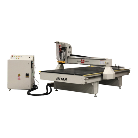
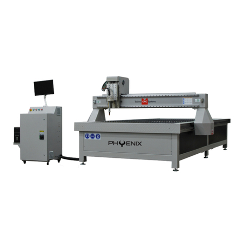
Techno CNC Systems Venture Series User manual

1For Support Visit· www.technocnc.com and click Support or Call: (631) 648-7481
(HTT0673)
Venture Series
This manual will provide unpacking, maintenance, and user guide for running the Techno Venture Series
and Venture Plus Series CNC Routers.
It is suggested that the operator keep this manual by the machine. This will provide the most important
information pertaining to the operation of this machine.
©2017 (05/08/2017)
WARNING: DO NOT OPERATE THIS MACHINE WITHOUT PROPER
TRAINING! Improper or unsafe operation of the machine will
result in personal injury and/or damage to the equipment.
Series CNC Router
User Manual

2For Support Visit· www.technocnc.com and click Support or Call: (631) 648-7481
(HTT0673)
Venture Series
TABLE OF CONTENTS
I......General Installation Instructions.
1.1 Forklift guide and unpacking instructions. ............................. Page 3
1.2 Safety Instructions. ............................. Page 4
1.3 Correct Colleting. ............................. Page 5
1.3.5 Toolstand 1.3.6 Spindle Warmup ............................. Page 6
1.4 Electrical and Pneumatic connections. ............................. Page 7 - 8
1.5 Vacuum Pump connections. ............................. Page 9
II.....Machine Start-Up and Screen Functionality.
2.1- Start up Procedure. ............................. Page 10 - 12
2.2- Screen Callouts. ............................. Page 13 - 25
2.3- File System-Network. ............................. Page 26
III... Operating Tutorials
3.1- Jogging the Machine. ............................. Page 27 - 28
3.2- Learning Tool lengths. ............................. Page 29 - 30
3.3- Saving an Origin | Setting XYZ Zero Position ............................. Page 31 - 32
3.4- Preparing a G-Code File. ............................. Page 33 - 34
3.5- Running a G-Code File. ............................. Page 35 - 36
3.6-MachineOrigin,WorkingOrigin,&Osets .............................Page37
IV.....Advanced Tutorials
4.1- Using Block to Block Function. ............................. Page 38
4.2-MemSearch. 4.3-ReturntoProle. .............................Page39
4.4- Setup Parameters. ............................. Page 40 - 43
4.5- Backing up Parameters. ............................. Page 44 - 46
V......Machine Lubrication ............................. Page 47
VI....Appendix
6.0- HSD Aggregate Tool Setup. ............................. Page 48 - 49
6.1- Service and Maintenance Guide ............................. Page 50 - 54
6.2- Fault Finding/Error Messages. ............................. Page 55 - 59
Becker Vacuum Pump Manual ............................... Page 60 - 64
Becker Vacuum Pump Filter Inspection ............................... Page 65 - 67
Becker Vacuum Pump Greasing Process ............................... Page 68 - 72
Warranty .......................... Page 73

3For Support Visit· www.technocnc.com and click Support or Call: (631) 648-7481
(HTT0673)
Venture Series
Techno CNC Systems Venture Series Forklift Guide
SAFETY WARNING:
DO NOT LIFT MACHINE OR MOVE MACHINE BY THE GANTRY
For safety and to prevent damage to the machine, Lift Machine Using The Frame ONLY
** Some Venture Series CNC Routers do NOT have forklift tubes. **
If so, make sure forklift blades enter through the frame of the machine only. Use blocks when lifting
machine to prevent damage to the vacuum table plumbing **
1. Unpack all items that shipped with your machine. Check the items on your slip to be sure nothing was left out. Notify Techno if you have any missing
pieces of your shipment.
2. A toolbox and other accessories, such as vacuum hosing and leveling feet, may be packed under the machine during shipping.
3. Forklift your machine up from the oor and remove the wooden pallet (if it was shipped on a wooden pallet).

4For Support Visit· www.technocnc.com and click Support or Call: (631) 648-7481
(HTT0673)
Venture Series
1.2 SAFETY INFORMATION!
1. Keepngers,hands,andallotherobjectsawayfrom
machinewhilepowerison.
2. Disconnectpowertoallsystemcomponentswhen
notinuse,whenchangingaccessories,andbefore
servicing.
3. Donotloosen,remove,oradjustmachinepartsor
cableswhilepowerison.
4. Exercisecarewithmachinecontrolsandaround
keyboardtoavoidunintentionalstarting.
5. Makesurevoltagesuppliedisappropriateto
specicationsofcomponents.
6. Machinesmustbepluggedintofour-pronged
groundedoutlets.Donotremovethegrounding
plugorconnectintoanungroundedextension
cord.
7. Keepcablesandcordsawayfromheat,oil,and
sharpedges.Donotoverstretchorrunthem
underotherobjectsoroverworksurfaces.
8. Useproperxturesandclampstosecurework.
Neverusehandstosecurework.
9. Donotattempttoexceedlimitsofmachine.
10. Donotattempttousemachineforpurposesother
thanwhatisintended.
11. Usemachineonlyinclean,well-litareasfreefrom
ammableliquidsandexcessivemoisture.
12. Stayalertatalltimeswhenoperatingthemachine.
13. Alwayswearsafetygoggles.
14. Donotwearjewelryorloose-ttingclothingwhen
operatingmachine.Longhairshouldbeprotected.
15. Alwaysmaintainproperbalanceandfootingwhen
workingaroundthemachine.
16. Maintainequipmentwithcare.Keepcutting
toolscleanandsharp.Lubricateandchange
accessorieswhennecessary.Cablesandcords
shouldbeinspectedregularly.Keepcontrols
cleananddry.
17. Beforeusing,checkfordamagedparts.An
authorizedservicecentershouldperformall
repairs.Onlyidenticalorauthorizedreplacement
partsshouldbeused.
18. Removeanyadjustingkeysandwrenchesbefore
turningmachineon.
19. Donotoperatethemachineunattended.
20. Followallsafetyinstructionsandprocessing
instructionsintheMSDSforthematerialbeing
processed.
21. Useproperprecautionswithdustcollection
systemstopreventsparksandrehazards.
Read these instructions thoroughly before operating
machine. DO NOT operate machine if you are unfamiliar with
these safe operating instructions. DO NOT operate machine
without knowing where the emergency stop switch is located.
PREVENTFIREHAZARDSbyusingtheproperfeeds,speeds,andtoolingwhileoperatingyourTechnomachine.
Forexample,settingfeedsandspeedstoolowand/orusingdulltoolbitscreatesfrictionatthematerial.The
frictiongeneratesheatwhichcanresultinarethatcanbedrawnthroughthevacuumtableordustcollector
withoutwarning.Firehazardfromfrictionheatingcausedbydulltoolsispossiblewhencuttingcertainmaterials,
especiallycompositematerialsuchaswoodcomposites,MDFandParticleboard. ©2015

5For Support Visit· www.technocnc.com and click Support or Call: (631) 648-7481
(HTT0673)
Venture Series
WARNING!
THE SPINDLE WILL BE DAMAGED
IF UNBALANCED EQUIPMENT IS USED.
AIR SUPPLY MUST BE FILTERED AND DRY.
1.3 Correct Colleting:
Read these instructions thoroughly
BEFORE operating machine.

6For Support Visit· www.technocnc.com and click Support or Call: (631) 648-7481
(HTT0673)
Venture Series
1.3.5 Tool Stand Diagram - Proper Placement
ReadtheseinstructionsthoroughlyBEFOREoperatingmachine.
1.3.6 —HSD
Spindle Warmup
Read these instructions thoroughly BEFORE operating machine.
USE AND ADJUSTMENT
PREHEATING
HSD S.p.A. uses high-precision angular contact bearing pairs, pre-loaded and lubricated for life
with special grease for high speeds.
When the machine is switched on for the first time every day, allow the electrospindle to perform a
brief preheating cycle in order to allow the bearings to gradually attain a uniform operating
temperature, and hence to obtain a uniform expansion of the bearing races and the correct preload
and rigidity.
The following cycle is recommended, without machining operations:
50 %of the maximum rated speed for 2minutes.
75 %of the maximum rated speed for 2minutes.
100 %of the maximum rated speed for 1minute.
The preheating cycle should also be performed every time that the machine is inoperative long
enough for the electrospindle to cool down to room temperature.
Only for HSK versions:
it is forbidden to run the electrospindle without the tool-holder inserted.
While the machine is operating, the spindle can reach high temperatures. Be very careful
not to touch it without due precautions.
Spindle Warm-up:

7For Support Visit· www.technocnc.com and click Support or Call: (631) 648-7481
(HTT0673)
Venture Series
1.4.2
AlltheelectronicsfortheVenturemachineare
locatedinthehousingcabinet.Donotopen
thesedoorswhenpowerisappliedtothe
machine.
1.4.3
Therearetworoundedconnectorsonthesideofthe
controller,theseconnectorsprovide220voltsforthe
vacuumpumpstartercontactors.
Leadthecablefor3phase220voltsthatwillbeusedto
powermachinethroughtheholeonthebottomofthe
cabinet.
Fig1.4.2
220Vinfor
powering
machine
220VOut
forVacuumPump
Network
Connection
Motor/
Encoder
Fig1.4.3.
1.4 Electrical and Pneumatic connections.
TheTechnoVentureseriesmachineispoweredbythreephase220
volts.Theamperagerequirementsforthismachineare40amps.
1.4.1
Whenthemachinehasbeenunpacked,itwill
benecessarytoattachthekeyboardshelftothe
frontofthemachine.
Whentheshelfisinplace,leadthemouseand
keyboardcablesthroughthesmallholeinthe
fontofthemachine.Plugthecablesintoan
availableUSBconnectiononthePC.
Screwstoattach
shelf
Fig1.4.1
Holeformouseand
keyboardcable
WARNING: Ensure that all electrical connections are
carried out by a qualied electrician.
Improper electrical connections can result in
damage to the equipment, re and death.

8For Support Visit· www.technocnc.com and click Support or Call: (631) 648-7481
(HTT0673)
Venture Series
1.4.4
Attachthethreephasesandthegroundtothe
connectionsshowning1.4.4aor1.4.4b
Yourmachinemaycomewithaterminalblock
(shownin1.4.4a)oryoumachinemaycomewith
noterminalblockandmustbewiredtothepower
switchshowningure1.4.4b
1.4.5
Variouscomponentsonthemachinerequireair
pressure.of90psiandneedstobesuppliedtothe
machineatalltimesforittofunctioncorrectly.
Attachanairhosetotheairinputonthebackofthe
machine.Seeg1.4.5.
Ifyourshophosedoesnotttheadaptorsupplied,the
adaptercanberemovedandasuitableoneattached.
3 phase
220V in
WARNING: Ensure that all electrical connections are
carried out by a qualied electrician.
Improper electrical connections can result in damage
to the equipment, re and death.
Fig1.4.5
Should read
90 psi
1.4.6
Removethefourbracketsusedtostabilizethegantry
duringshippingusingmetricallenwrenchs.Theremay
bebracketsattachedtotheXandZaxis,aswell.
Fig1.4.6
Fig1.4.4a.
Fig1.4.4.b
3 phase
220V in

9For Support Visit· www.technocnc.com and click Support or Call: (631) 648-7481
(HTT0673)
Venture Series
1.5 Vacuum Pump connections
YouwillneedtohaveanelectricianconnectACpower
(220or440VAC)asspeciedontheunittothemotor
starter.
TakethesilverconnectorfromtheStarterBoxand
connectittothefemaleconnectoronthemain
electronicunit.
Attachthesilverconnector
fromthestarterboxhere.
Attachthehosesfromthemachinetothe
T-connectorsandattachthemtothepump.
WARNING: Direction of Rotation is critical.
Briey start motion and check rotation (arrow on casing).
Exchange phases if rotation is incorrect.
IF YOU RUN THE PUMP/BLOWER CONTINUOUSLY IN THE WRONG
DIRECTION, THE VANES WILL BE DAMAGED
Turnonindividualsectionsofthe
vacuumtablebyturningthemanifold
handlesinthefrontofthemachine.
Vacuum on and off functions are
controlled by the Osai controller
and can only be turned on from
the computer screen.
To test the motor, press the
reset button on the starter box
once all connections are made.
1
2
4
3

10 For Support Visit· www.technocnc.com and click Support or Call: (631) 648-7481
(HTT0673)
Venture Series

11 For Support Visit· www.technocnc.com and click Support or Call: (631) 648-7481
(HTT0673)
Venture Series
Section II: Machine Start-Up | Screen Functionality
2.1.1Turn the Main power switch to the ON
Position.220Voltsshould havebeenran to
themachinebyanelectrician.220Visgoing
to be attached to the back of the switch
(below)orattachedtotheterminal(below)
*E-Stop may have been pushed in for
shippingpurposes*
2.1.2
Theredlightonthefrontofthe
machinewilllightup.Thisindicates
that220voltsiscomingintothe
machine.
ThePowerONlightwilllightup
indicatingthatpowerhasbeen
appliedtothecontrollersystemand
themotors.
2.1- Start up Procedure.
Power
O
Power
ON
OSAI
Power
Switch
MUST
BEON!
PC
Power
E-stop:
Turnso
controller,
motorand
spindle
USB
Port
1
2
4
3
Fig2.1.2
PressthePowerONbuttontostart
thesystem.
PresstheComputerPowerbutton
tostartthePC.Thismayonlylight
temporarily.ThePCwillstarttoboot.
5
Terminal

12 For Support Visit· www.technocnc.com and click Support or Call: (631) 648-7481
(HTT0673)
Venture Series
2.1.4Softwarestartup.
OncethePChasstarted,theBootControllersoftwarewillstartautomatically.Ifitdoesnot,doubleclick
ontheBootControllerIcon(Itlookslikearocketship)onthedesktop.Ifnotextappearsinthebox,after30
seconds,checkthatthelightforthecontrollerisonandthatthenetworkcablefromPCtoOsaicontrolleris
connected.Ifnoconnectionoccurs,seetheFaultFindingsectionintheAppendix.
IftheBootControllerdoesnotstartafteraminuteandthemessageCNCiswaitingforaBOOTmodedirective
appearsonthescreen,thennormalmodeneedstobeselected.
Bootcontrollerloaded
andconnectingto
machine
Controlleriswaiting
foramode.
Ifthemachineisstarting
fromafreshPCboot,
thenNormalmodewill
automaticallybeselected.
192.168.0.1
192.168.0.1
* Otherwise,itwill
automaticallygointo
normalmodeafterafew
seconds.

13 For Support Visit· www.technocnc.com and click Support or Call: (631) 648-7481
(HTT0673)
Venture Series
2.1.5InterfaceStarts:
TheTechnointerfacescreen
willnowopen.Therewillbe
awarningmessagesaying
EmergencyStopActive.
ClickontheE-stopReset
Buttontoremovethis
warning.
TheAxisnotreferencederrorwillappear.
Clickon“HomeAll”andalltheaxeswillmovetotheirhomeposition.Ifanyerrorsremainonthescreen(i.e.Low
AirPressure,)rectifytheproblemandclickon“ResetErrors”or“RESET”toremovethemessage.
Themachineisnowreadytobejogged.
HomeAll
ResetErrors
Note:PressingHomeAll
willmovethemachine
tothefrontleftcornerof
thetable.
Thismustbedoneevery
timethemachineboots
up.
Oncethemachineisin
theHomeposition,it
hasareferencepoint
fromwhichitcanpickup
toolsandlocateosets.

14 For Support Visit· www.technocnc.com and click Support or Call: (631) 648-7481
(HTT0673)
Venture Series
2.2 Screen Callouts
AboveisthemainscreenoftheTechnoVentureinterface.
Tohelpunderstandthefunctionsofthebuttonstheywillbebrokendownintothefollowingcategories:
A-Joggingfunctions.
B-HomingFunctionsandClearancePosition
C-PneumaticandElectricalControls.
D-MenuSystems.
E-CoordinateSystems.
F-OriginFunctions.
G-SaveOriginMenu
H-SpindleandCoolantcontrol.
I-LoadG-codeFile.
J-ProgramFunctions.
K-ToolMenu
L-OsetMenu.
A
B
C
D
E
F
G
H
J
K
L

15 For Support Visit· www.technocnc.com and click Support or Call: (631) 648-7481
(HTT0673)
Venture Series
Themachinewillnotmoveunlessajogmodeisselected.Clickonthebuttonbesidethetext
toselectamode.
A-Handwheel:
Inthismode,themachinewilloperateviatheMPG/Handwheel.PleaseseeHandwheel
operationformoreinformation.Allotherfunctionsaredisabledwhenthisisactive.
B-Continuous:
Also,knownasJogMode.Themachinewillmovesmoothlyandcontinuouslywhenthe
userclicksonthedirectionalarrowassociatedwitheachaxis.SpeediscontrolledbyJog
speedandisapercentageofthemaxjogspeed(800ipm)formanualjogmode.(Ex:[50%of
800=400IPM])
C-Step:
Also,knownasIncrementalJogMode.Themachinewillmovebyanexactamount,as
speciedbyJogStepvariablewhenthearrowbuttonishelddownwithleftclick.[Example:if
jogstepissetto.05andIclickX+.machinemoves.05toright]
D-MDI:
ManualDataInput,thisfeatureallowstheusertomanuallyenterandexecutealineofG-code.
[Ex:(M3S1800:spindleturnsonat18,000rpm)]
E-JoggingArrows:
Byleftclickingonthesearrowsthemachinewillmoveinthecorrespondingdirection.These
arrowsareonlyfunctionalifContinuousorStepmodeisactive.
F-ResetErrors:Thiswillremoveanywarning/errormessagesthatappearonthescreen.
A
B
CD
E
F
A-Jogging Functions

16 For Support Visit· www.technocnc.com and click Support or Call: (631) 648-7481
(HTT0673)
Venture Series
A-HomeAll:
Sendsthemachinetothehomeposition.(AbsoluteXYZ=0).TheZaxiswillrstmoveuptoits
limit,thentheXandYaxeswillmovesimultaneously.
B-SINGLEAXISHOME:
Whenthisbuttonisleftclicked,eachaxiscanbehomedseparately.Whenthebuttonisactive,
theuserthenclicksonthearrowkeyfortheaxistobehomedtoenabletheoperation.[Ex:
clicksingleaxishome,clickX-,machinewillhomethex-axisonly]
C-CLEARANCEPOSITION:
Whenthisbuttonisleftclicked,themachinewillruntowardstheback,inordertoloadand
unloadwork
B-Homing Functions
A
B
C

17 For Support Visit· www.technocnc.com and click Support or Call: (631) 648-7481
(HTT0673)
Venture Series
C-Pneumatic and Electrical Controls
Thesectionshighlightedbelowarethebuttonsthatcontrolthepneumaticandelectrical
outputsforthecontroller.
A
B
C
D
A-ShroudUp/Down:
Thisbuttonwillraiseorlowerthedustshroudonthespindle.
B-PinsUp/Down:
Thisbuttonwillraiseorlowerthepop-uppinsonthesidesofthetable.
C-Vacuum1On/O:
ThisbuttonwillturnVacuum1onando,ifitisconnected.
D-Vacuum2On/O:
ThisbuttonwillturnVacuum2onando,ifitisconnected.
ShroudUp/DownandPinsUp/Downwillonlyfunctionif90lbs.ofcompressedairconnectedtothe
machine
Vacuum1on/oandVacuum2on/osend220voltstothestartercoilofthevacuumpump,thus
activatingthepump.
Down Up
Down Up

18 For Support Visit· www.technocnc.com and click Support or Call: (631) 648-7481
(HTT0673)
Venture Series
A
B
C
D-Menu Screens
ThesectionshighlightedbelowaretheMenuScreenoptionsoftheinterface.Theusercan
switchtothesescreensbyclickingonthecorrespondingbutton.
A-Osets:
OpenstheOsetMenu.Inthismenutheusercansavemultipleosets/origins
andapplythemtothecoordinatesystem.
B-I/O:
OpenstheInputandOutputscreendiagnostics.Thesescreenswillshowthe
statesoftheinputsandoutputs.
C-Tool:
OpenstheToolMenu.Inthismenutheusercanstoretoollengthsandchange
toolnumbers.

19 For Support Visit· www.technocnc.com and click Support or Call: (631) 648-7481
(HTT0673)
Venture Series
E-Coordinate System
A
B
C
D
A-XYZCoordinates:
Thisdisplaysthelocationofthemachine.IftheOriginNoiszero,thenumbersdisplayed
arethedistancefromtheHomeposition(AbsoluteXYZ=0).IfthereisanOriginNumber
active,thenumbersdisplayedarethedistancefromthatoriginszeroposition.
B-Tool:
Thisdisplaysthetoolthatiscurrentlyinthespindle.Ifthenumberreadsasingledigitthen
thereisnoosetappliedtothattoolatthistime.WhentheTooldisplays1.1,or2.2,or5.5
etcthentheZ-osetisactive.TheZ-osetneedstobeactivewhensettingtheorigin.
C-OriginNo:
Thisdisplaystheactiveorigin/coordinatesystem.Whenitreads0,nooriginisactiveand
thecoordinatesystemdisplayedisthefromtheHomeposition.Thesystemissetupto
accommodate8origins,butmanymorecanbemadeavailable.
D-ZOset:
ThisistheamountofZ-osetbeingappliedtothetool.Z-osetisthedistancefromthe
homepositionanditissetintheToolmenuusingthetoolcalibrationblock.

20 For Support Visit· www.technocnc.com and click Support or Call: (631) 648-7481
(HTT0673)
Venture Series
F-Origin Functions
A
B
C
A-APPLYORI1:
LeftclickingonthisbuttonactivatesOrigin1forthecoordinatesystem.
B-GOTOXY0ORI1:
LeftclickingonthisbuttonmovestheZaxistothehomepositionand
theXYaxestotheX-zero,Y-zeroforOrigin1.(XY=0)
C-SaveOrigin:
LeftclickingonthisbuttonopenstheSaveOriginScreenSafeMode
Option.Inthisscreentheusercansavethepositionofthemachine
astheOrigin.ThisiswheretheusersetsXYZzero.ThisSafeMode
Optionwillprovideadditionalwarningsandopportunitiesfortheuser
toensurethattheoriginissavedcorrectly.
Origincanalso
becalledtheXYZ
zeropoint.
Other Techno CNC Systems Control System manuals
