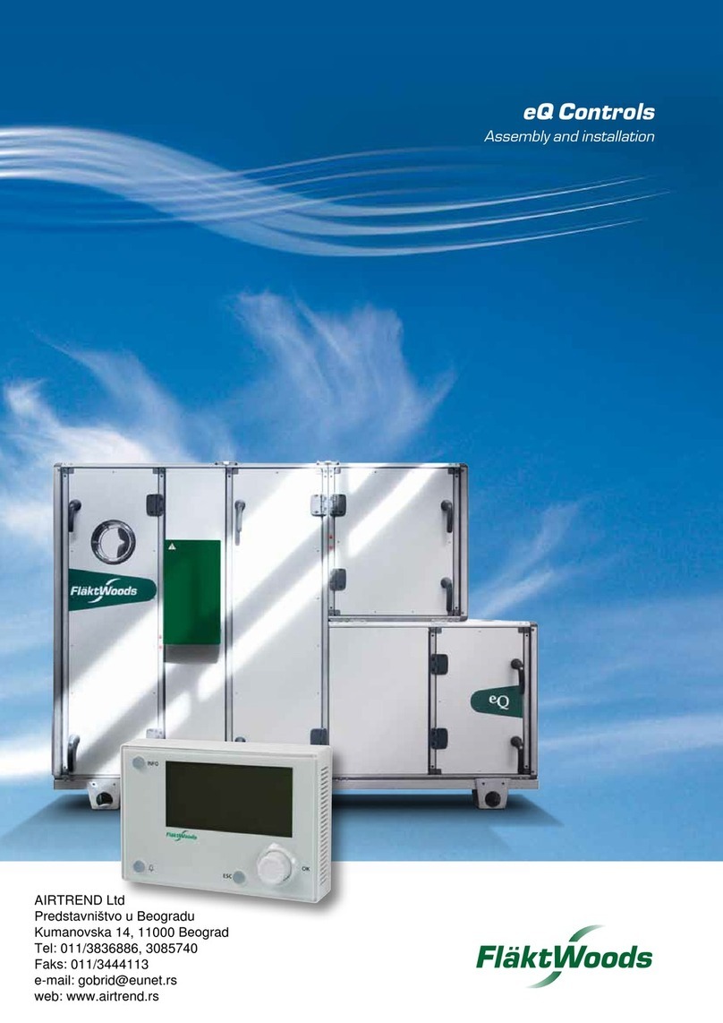
flakt woods FICO FCLA-128 Manual

Cotrol system FICO-128
Installation, use and maintenance
09/2014

2
Fläkt Woods FIFLO EN 2014.09 All rights reserved.
Control System FICO-128 INSTALLATION, USE AND MAINTENANCE
Contents
1. Connection instructions, system with individual indication .....................................................................................3
2. Topology of FICO FCLA-128 with one and two communication loops ..................................................................4
3. Topology of FICO FCLA-128 with two communication loops and four fan interlocks
(Groups A, B, C, and D) ...................................................................................................................................................5
4. Control unit FCLA-128 ....................................................................................................................................................6
5. Communication unit FCBA-2 and relay unit FCFA-1 .................................................................................................7
6. Installing communication unit FCBA-2 ........................................................................................................................9
7. Installing control unit FCLA-128 ..................................................................................................................................10
8. Taking FCLA-128 with its FCBA-2 communication units into use .........................................................................11
9. Ĵȱ .............................................................................................................................................................................15
10. Adding / changing fan groups .................................................................................................................................... 16
11. Controlling operating status .........................................................................................................................................16
12. Manual test of dampers, communication units, and groups ...................................................................................17
13. Ĵȱěȱȱȱȱȱȱȱȱȱȱȱȱ .......................18
14. Adding a communication unit to the system .............................................................................................................19
15. Adding a relay unit to the system ............................................................................................................................... 21
16. Connecting damper motor / smoke detector to a communication unit with only one damper motor /
smoke detector connected to it .....................................................................................................................................23
17. Disconnecting damper motor / smoke detector from a communication unit with two damper motors /
smoke detectors connected to it ...................................................................................................................................24
18. Disconnecting communication unit / relay unit from the system ...........................................................................25
19. Alarms at control unit FCLA-128 ................................................................................................................................ 26
20. Alarms at communication unit FCBA-2 ..................................................................................................................... 27
21. Alarm codes and situations in FCLA-128 shown in Alarm History ...................................................................... 28
22. ¢ȱȱĴ¢ȱȱȱȱȱȱȱȱȱȱȱ.................................... 28
23. ĴȱȱȱȬŗŘŞȱȱ¢ȱĴȱ................................................................................................. 29
24. Aid for system documentation .................................................................................................................................... 30

3
INSTALLATION, USE AND MAINTENANCE
Fläkt Woods FIFLO EN 2014.09 All rights reserved.
Control System FICO-128
1 Connection instructions, system with individual
indication
1 Connection instructions, system with
individual indication
1.1 General
Control unit FCLA-128, communication unit FCBA-2, and
relay unit FCFA-1 contain electronic components that can be
damaged if handled incorrectly. Before connecting power,
all external installations shall be completed.
Control unit FCLA-128, communication unit FCBA-2, and
relay unit FCFA-1 are mounted with 4 screws located under
the enclosure cover to ensure protection class IP54.
1.2 Inputs FCLA-128
Supply voltage AC 230 V 2A, connectors L, N, and PE. Ex-
ample of electric cable type: EKK3G1,5
1.3 Outputs
All relay outputs are potential-free contacts shown in a
dead state.
ȱȱȱȱęȱȱǻȱǼȱȱ
the FCLA-128 are designed for 24 V, 3 A resistive load.
Summation alarm contacts for service alarm (marked SER-
VICE) in the FCLA-128 are designed for 24 V, 3 A resistive
load.
Relay contacts for interlocking of fans (marked FAN A and
FAN B) in the FCLA-128 are designed for 230 V, 3 A resis-
tive load. Example of electric cable type: EKK....
If you need more relay contacts for interlocking of fans, the
system can be expanded with relay unit FCFA-1.
1.4 Damper actuators
Damper actuators are connected to communication unit
FCBA-2; up to 64 actuators per loop with individual indica-
tion can be connected to the system, but max. two loops per
communication unit. Control unit FCLA-128 has two loops
available. For a complete system with 128 damper actuators
you must use both loops (Link 1 and Link 2).
Supply voltage to actuators 1 and 2 is connected in com-
munication unit FCBA-2 to connectors 1 and 2 (marked
MOTOR). Indications for closed damper are connected to
connectors S1 and S2 (marked MOTOR SWITCHES) and in-
dications for open damper to connectors S4 and S6 (marked
MOTOR SWITCHES).
S3 and S5 are not used and shall be insulated.
1.5 Smoke detectors
Smoke detectors are connected to communication unit
FCBA-2; up to 64 smoke detectors per loop with individual
indication can be connected to the system, but max. two
loops per communication unit. Control unit FCLA-128 has
two loops available. For a complete system with 128 smoke
detectors, you must use both loops (Link 1 and Link 2).
You can choose between three alternative smoke detectors
Siemens Rököga SOS2... or Calectro UG-3-... or Calectro
EVC-PY-DA.
When Siemens Rököga SOC2... is used, you can adjust the
sensitivity of the detector.
If you use Calectro UG-3-... smoke detectors, you must con-
nect the included 2.2 kohm resistor to the smoke detector
between connectors 1 and 5.
If you use Calectro EVC-PY-DA smoke detectors, you must
connect the 2.2 kohm resistor to the smoke detector between
connectors 1 and 3.
1.6 Operating of fans
Control unit FCLA-128 has two relay outputs (two groups)
for interlocking fans. For more relay outputs / groups, a re-
lay unit FCFA-1 must be connected. Up to eight relay units
can be connected to the system. (This means up to a total of
ten relay outputs/groups.)
1.7 Connecting communication to communication
unit FCBA-2
Control unit FCLA-128 has two connectors for connecting
communication wires between control unit FCLA-128 and
communication units FCBA-2 (LINK 1 and LINK 2). Max.
32 communication units can be connected to each commu-
nication loop.
Note! An individual address should be set for every com-
munication unit (FCBA-2) that shall be connected to the
control unit (FCLA-128) regardless of whether it is con-
nected to the LINK 1 or LINK 2 or not.
Type of electric cable:
ȱĜȱȱȬȱŘ¡Ř¡Ŗǯś
For industrial use ELAKY 2x2x0.6
1.8 Connecting communication to central control
and monitoring system
Control unit FCLA-128 has connectors for connecting com-
munication wiring (marked MODBUS slave) to a parent
system for control and monitoring.
1.9 External inputs
There are two inputs for external interlocking:
ȱȱ¡ȱęȱDZȱȱȱȱ¡ȱęȱǰȱ
dampers are closed and fan interlocking is activated, possi-
¢ȱȱȱȱȱ¡ȱęȱȱȱȱ
reset. These connectors are normally jumpered, and the
jumper is removed when this function is connected.
Input for external interlocking: Dampers are closed and fan
interlocking is activated. Normal status returns when the
interlocking is removed.
These connectors are normally jumpered, and the jumper is
removed when this function is connected.
1.10 Fan groups (zones)
To be able to interlock (stop) the fans in the system, the re-
lays in the control unit FCLA-128 must be activated (Groups
A and B), with Group A being preselected. If you need more
groups, you must connect relay units to the control unit,
which with max. 8 relay units per control unit will allow 10
relays (groups) for controlling fans.
All communication units in the system must have a desig-
ȱȱȱȱȱȱȱȱȱȱęǰȱȱ-
cate damper faults, to indicate communication failures, and
to carry out damper testing.

4
Fläkt Woods FIFLO EN 2014.09 All rights reserved.
Control System FICO-128 INSTALLATION, USE AND MAINTENANCE
2 Topology of FICO FCLA-128 with one and two
communication loops
FICO FCLA-128
FCBA-2
FCBA-2
FCBA-2
Interlocking of fan FAN 1
Communication to parent system
Supply 230 V Output fire alarm
Output service alarm
Interlocking
FAN2
Interlocking
Supply 230V
Supply 230V
Supply 230V
FICO FCLA-128
FCBA-2
FCBA-2
FCBA-2
FCBA-2
Communication to parent system
Supply 230 V Output fire alarm
Output service alarm
Interlocking of fan FAN1 (Group A)
Interlocking of fan FAN2 (Group B)
Interlocking
FAN2
Interlocking
Interlocking
Supply 230V
Supply
230V
Supply
230V
Supply 230V
Interlocking
FAN1

5
INSTALLATION, USE AND MAINTENANCE
Fläkt Woods FIFLO EN 2014.09 All rights reserved.
Control System FICO-128
3 Topology of FICO FCLA-128 with two communication
loops and four fan interlocks (Groups A, B, C, and D)
FICO FCLA-128
FCBA-2
FCBA-2
FCBA-2
FCBA-2
FCBA-2
FCBA-2
FCBA-2
FCBA-2
FCFA-1
FCFA-1
Communication to parent system
Supply 230 V Output fire alarm
Output service alarm
Interlocking of fan FAN1 (Group A)
Interlocking of fan FAN2 (Group B)
Interlocking
FAN2
Interlocking
Supply
230V
Supply 230V
Interlocking
FAN1
Supply 230V
Supply
230V
Interlocking
Interlocking
Supply 230V
Supply 230V
Supply 230V
Interlocking
Group C
Supply
230V
Supply
230V
Supply 230V
Interlocking
Group D
Interlocking

6
Fläkt Woods FIFLO EN 2014.09 All rights reserved.
Control System FICO-128 INSTALLATION, USE AND MAINTENANCE
4 Control unit FCLA-128
1 Supply connection AC 230 V
2 Connection of fan interlocking FAN 1 (Group 1) and FAN 2 (Group 2)
3 Connection of output summation alarm for FIRE (8 = NO, 9 = C and 10 = NC)
4 Connection of output summation alarm for SERVICE (11 = NO, 12 = C and 13 = NC)
5 Input for external interlocking. Needs no acknowledging at control unit FCLA-128.
6 Input for external fire alarm. Alarm must be acknowledged at control unit FCLA-128.
7 Connectors for communication loop between control unit and communication units/relay units
8 Connectors for communication loop to parent system for control and monitoring
9 Connector (RJ45) for updating control unit FCLA-128
10 LINK 1 Indicates data transfer in comm. loop 1, flashes green
LINK 2 Indicates data transfer in comm. loop 2, flashes green
MODBUS Indicates data transfer in MODBUS, flashes yellow
SYSTEM Indicates voltage, illuminates green
11 AUTO/STANDBY Illuminates green when in use Flashes green in STANDBY
FIRE ALARM Flashes red for alarm Illum. red for acknowledged alarm
EXTERNAL ALARM Flashes red for external fire alarm Illum. red for acknowledged alarm
INTERLOCK Illum. red for active external interlocking
SERVICE ALARM Flashes yellow for service alarm
FAN STOPPER Illum. red for activated fan interlocking
COM ERROR Flashes red for communication error
L
N
PE
4
5
6
7
230 VAC FAN A FAN B
8
9
10
11
12
13
14
15
19
20
21
22
23
24
25
26
18
16
17
FIRE SERVICE ILOCK EXT. LINK 1 LINK 2
Max 24V/3A INPUTS Max 32 UNITS/LINK
ESC
EDIT
ENTER
INFO
ALARM
RESET
AUTO/STANBY DAMPER TEST
FIRE ALARM
EXTERNAL ALARM
INTERLOCK COM ERROR
FAN STOPPED
SERVICE ALARM
FCLA-128
FICO
MODBUS
SLAVE
Max 230VAC/3A
AUX
3578
124
9
LINK1
LINK 2
MODBUS
SYSTEM
10
6
11
FIRE DAMPER CONTROL UNIT
LINK1
LINK 2
MODBUS
SYSTEM

7
INSTALLATION, USE AND MAINTENANCE
Fläkt Woods FIFLO EN 2014.09 All rights reserved.
Control System FICO-128
5 Communication unit FCBA-2 and relay unit FCFA-1
1 Supply connection AC 230 V
2 DIP switch activating damper motor and smoke detector
3 Indicators for damper position and status of smoke detector
4 Connectors for pre-connected damper motors and smoke detectors
5 Damper motor test
6 End resistor of communication bus, activated in last communication unit / relay unit of each loop
7 Connection of communication bus
8 Setting of communication unit address (example: address 5 = 0 on the left switch and 5 on the right switch)
9 Updating of communication unit
10 Connectors for damper motors and smoke detectors
11 LEDs indicating operating status
LED indicates open damper with illuminating green
LED indicates closed damper with illuminating yellow
LED indicates fire alarm with illuminating red
LED indicates service alarm with illuminating yellow
DIP switch 1 to ON for connected damper in communication unit
DIP switch 2 to ON for connected smoke detector in communication unit
AS ON
1
2
2
3
AS ON
1
2
2
3
ON
1
2
ON
1
2
S
A
Communication unit FCBA-2
N
PE
LR
KOMM.
L
1
2
S1
S2
S4
S6
G1/2
M1/1
B1
1
2
S1
S2
S4
S6
G1/2
M1/1
B1
MOTOR
MOTOR-
SWITCHES DETECTOR MOTOR
MOTOR-
SWITCHES DETECTOR
B
T
A
UPDATE
ADDRESS 0-99
ON
1
2ON
1
2
ON
1
2
1
44
22
6
7
8
9
5
10 10
33STATUS
PROG.
COMM ERR
LINK
11
B
T
A
230 VAC
DAMPER TEST
ASAS
COMM.

8
Fläkt Woods FIFLO EN 2014.09 All rights reserved.
Control System FICO-128 INSTALLATION, USE AND MAINTENANCE
1 Supply connection AC 230 V
2 Connection for fan interlocking
3 Connection for communication loop (input and output)
4 LEDs indicating operating status
5 Address switch
6 Updating of relay unit
7 Explanations of address switch
8 End resistor of communication bus, activated in last communication unit / relay unit of loop
N
PE
LINK
L
B
T
A
ADDRESS
ON
1
2
POWER ON
FAN ON
COMM ERR
LINK
FAN
ADR GRP
1
2
3
4
5
6
8
7
C
D
E
F
G
H
I
J
123
4
5
6
7
8
UPDATE
230 VAC
Relay unit FCFA-1

9
INSTALLATION, USE AND MAINTENANCE
Fläkt Woods FIFLO EN 2014.09 All rights reserved.
Control System FICO-128
6 Installing communication unit FCBA-2
Note! All installation work must be done with power to
the system disconnected. On numbering of FCBA-2,
see Figure (page 7)
1 Connect power supply cables AC 230 V to communication unit
FCBA-2 according to high-voltage regulations.
1
2 Connect communication wiring to communication unit and fur-
ther on to next communication unit (FCBA-2) or control unit
(FCLA-128), with the loop connected in series and wires not
exchangeable.
7
3 Connect 24 V supply for damper motors to connectors 1 and
2, alternatively connect with quick couplings (motor wiring pre-
connected at the factory).
Connect damper motor limit position wiring to connectors S1,
S2, S4, and S6, or use quick couplings.
Wires 3 and 5 from damper motor are not used and must be
insulated.
10
4 Connect smoke detector Siemens SOS2... to connectors
G1/2, M1/1, and B1.
NOTE! Connect one smoke detector per input and max. two per
communication unit.
10
5 Connect Calectro EVC-PY-DA smoke detector to connectors
G1/6 and M1/3.
NOTE! Do not forget the end resistor between connectors 1
and 3 in smoke detector.
NOTE! Connect one smoke detector per input and max. two per
communication unit.
10
6 Connect Calectro UG-3-... to connectors G1/2 and M1/1.
NOTE! Do not forget the end resistor between connectors 1
and 5 in smoke detector.
NOTE! Connect one smoke detector per input and max. two per
communication unit.
10
7 Activate DIP switches of damper motors and smoke detectors
after connecting them in the communication unit (FCBA-2).
NOTE! Separate activation for left (L) and right (R) side of com-
munication unit.
(for example, if you have a damper motor connected, set the upper switch to ON).
(for example, if you have a smoke detector connected, set the lower switch to ON).
2
8 Set address using address switches for communication unit
(FCBA-2).
(for example, address 1 = 0 on the left and 1 on the right)
(for example, address 15 = 1 on the left and 5 on the right)
Address 01 will be shown first on display.
NOTE! An individual address should be set for every communication
unit (FCBA-2) that shall be connected to the control unit (FCLA-128)
regardless of whether it is connected to the LINK 1 or LINK 2 or not.
8
9 In the last communication unit /relay unit in each communication
loop, the end resistor must be activated. (LINK1 and LINK 2).
Set DIP switches 1 and 2 to ON.
6
1
2
S1
S2
S4
S6
MOTOR
MOTOR-
SWITCHES
1
2
1
2
4
6
B
T
A
19
20
18
FCLA-128
FCBA-2
Not exchangeable
N
PE
L
230 VAC
G1 2
M1 1
B1
DETECTOR
1
5
2
2,2 kOhm
G1 2
M1 1
B1
DETECTOR
M1
B1
G1
GREY
BLACK
RED
ON
ADDRESS 0-99
ON
1
2
Black field indicates DIP switch position
Black field indicates DIP switch position
G1 2
M1 1
B1
DETECTOR
3
1
6
2,2 kOhm

10
Fläkt Woods FIFLO EN 2014.09 All rights reserved.
Control System FICO-128 INSTALLATION, USE AND MAINTENANCE
7 Installing control unit FCLA-128
Note! All installation work must be done with power to
the system disconnected.
1 Connect power supply cables AC 230 V to control unit FCLA-
128 according to high-voltage regulations.
1
2 Connect fan interlocking for Group A to connectors 4 and 5.
Connect fan interlocking for Group B to connectors 6 and 7
2
3 Connect summation alarm outputs for FIRE and
SERVICE.
Opening at alarm, connectors 9 and 10.
Closing at alarm, connectors 9 and 8.
Opening at alarm, connectors 12 and 11.
Closing at alarm, connectors 12 and 13.
3 4
4 Connectors for external fire alarm. Must be acknowledged at
control unit FCLA-128 after resetting central fire alarm.
Connectors for external interlocking. Needs no acknowledging
at control unit FCLA-128.
Remove jumper at connectors 14 and 15 if you are using input
for EXTERNAL fire alarm.
Remove jumper at connectors 16 and 17 if you are using input
for EXTERNAL interlocking.
5 6
5 Connect communication loop
LINK1 (max. 32 communication units)
LINK2 (max. 32 communication units).
You can use both communication loops even if you have less
than 32 communication units
NOTE! All communication units / relay units must be con-
nected in series.
7
6 If the system is to be connected to a parent system for control
and monitoring, MODBUS slave must be connected.
NOTE! Conductors are not exchangeable.
8
N
PE
L
230 VAC
4
5
6
7
FAN A FAN B
8
9
10
11
12
13
FIRE SERVICE
14
15
16
17
ILOCK EXT.
19
20
21
22
23
18
LINK 1 LINK 2
B
A
FCLA128
FCBA-2
24
25
26
MODBUS
SLAVE
On numbering of FCLA-128,
see Figure (page 6)

11
INSTALLATION, USE AND MAINTENANCE
Fläkt Woods FIFLO EN 2014.09 All rights reserved.
Control System FICO-128
8 Taking FCLA-128 with its FCBA-2 communication
units into use
Example of taking into use a system with three communication units, all of which are to be connected to fan interlock-
ȱȱǯȱȱȱȱȱȱȱǰȱȱȱȱęǰȱȱȱ¢ȱȱȱȱȱ
Chapter 9; with more than two groups, Chapter 13 as well.
1 Before starting control unit settings, all installations of periph-
eral components shall be completed. See Chapters 6 and 7.
If addresses were not set in communication units when install-
ing them, it is advisable to do it at this point before continuing.
See Chapter 6, Item 7.
2 In order to facilitate start-up and to have automatic reading of
communication unit / relay unit addresses, they must always
be switched on before the control unit.
3 Switch on the control unit FCLA-128.
If you forgot to switch on the communication units / relay units be-
fore the control unit, press UPDATE at communication unit / relay
unit.
4 Press ENTER.
5 Go to Log in using the arrow keys, and press ENTER.
FICO FCLA-128
FCBA-2
Adr.01
FCBA-2
Adr.02
FCBA-2
Adr.03
TF FF
Output fire alarm
Output service alarm
Interlocking of fan (Group A)
Supply 230V
Group A
Supply 230V
Supply 230V
Supply 230V
UPDATE
During any configuration, the system shall be in Standby. See Chapter 9.2

12
Fläkt Woods FIFLO EN 2014.09 All rights reserved.
Control System FICO-128 INSTALLATION, USE AND MAINTENANCE
6 Log into the system using code 1000.
Use the arrow keys to select a number, and press
ENTER after each number. If your code was correct Login
level 1 is shown.
7 Press ENTER.
8 Setting language, date, and time:
Go to Settings using the arrow keys, and press ENTER.
9 Setting language:
Go to Language and press EDIT, then use the arrow keys to
go to the desired language, and press ENTER.
10 Setting date:
Press ARROW DOWN once to go to Date, press EDIT, set
year, month, and day using the arrow keys, then press ENTER
to finish.
11 Setting time:
Press ARROW DOWN once to go to Time, press EDIT, set
hours and minutes using the arrow keys, then press ENTER to
finish.
Press ESC to continue.
12 Go to Config system using the arrow keys, and press
ENTER.
Note! If no “Config system” line is shown, the system is on
Auto. Set the system to Standby. See Chapter 9.2
13 Go to System and press ENTER.
14 01 Shows communication unit address
- Shows if communication unit is activated
A Shows the Group of the communication unit
Shows if a damper motor is connected [L]
Shows if a smoke detector is connected [L]
Shows if a damper motor is connected [R]
Shows if a smoke detector is connected [R]
Example of display with several
addresses and groups
ENTER
123
45
8
6 PASSWORD
7
0
9

13
INSTALLATION, USE AND MAINTENANCE
Fläkt Woods FIFLO EN 2014.09 All rights reserved.
Control System FICO-128
15 Under the System menu you must activate the communication
units (En).
Press EDIT twice.
16 Press ARROW UP to activate communication unit with ad-
dress 01, then press ENTER.
Group A is always preselected (to change fan group,
see chapter 10).
17 Press ARROW DOWN to activate the next communication unit
with address 02.
18 Press EDIT once, press ARROW UP once, then press EN-
TER.
Group A is always preselected (to change fan group, see Chap-
ter 10).
19 Continue to activate communication unit with address 03.
Press ARROW DOWN, press EDIT once, press ARROW UP
once, then press ENTER.
Group A is always preselected (to change fan group, see Chap-
ter 10). If your system has several communication units, re-
peat the procedures until you have activated them all.
20 The display looks like this when you have finished.
If you want more fan groups, see Chapter 10.
21 Press ESC three times.
Go to Save config and Exit and press ENTER.
22 To start the system you must go to System mode menu and
then press ENTER.
Press ARROW UP to come to System mode, then press EN-
TER.
23 Press EDIT, then ARROW UP, and finish with ENTER. The
system will start, dampers open and the interlocking contact to
fan will disconnect when the dampers are open.
24 Press ESC.

14
Fläkt Woods FIFLO EN 2014.09 All rights reserved.
Control System FICO-128 INSTALLATION, USE AND MAINTENANCE
25 Go to Test & Maintenance to set the time and interval for
damper test. Go to Schedule and press ENTER to enter the
next menu.
26 Select Test time (= desired time for damper test).
Press EDIT, set hours and minutes using the arrow keys,
press ENTER to finish.
Go to Test interval (= how often do you want the dampers to
be tested).
Press EDIT and then ARROW UP, select desired damper test
interval: 24, 48, 72, 96, 120, 144, or 168 hours or once a
week. If you choose damper test once a week, you must also
set the day of the week when this is to take place, and press
ENTER to finish.
Press ESC twice to enter Menu.
27 Finish by running a manual test of the system, see Chapter
12.

15
INSTALLATION, USE AND MAINTENANCE
Fläkt Woods FIFLO EN 2014.09 All rights reserved.
Control System FICO-128
9 Settings
9.1 Logging into the system
1 Press ENTER on the control unit to enter Menu.
Go to Log in using the arrow keys, and press ENTER.
2 Log into the system using code 1000.
Use the arrow keys to select a number and press
ENTER after each number. If your code was correct, Login:
Level 1 is shown.
3Press ENTER to enter Menu.
The system is set to Standby through System mode on the control unit. The system must always be set to
Standby before changing configuration.
1 Log in, if you already have not done so, see Chapter 9.1.
Go to the System mode menu using the arrow keys, and press
ENTER.
2 Go to Mode, press EDIT and then press ARROW DOWN to
enter Standby.
3 Press ENTER.
4 The whole system is now in Standby, press ESC.
1 Go to System mode and press ENTER.
2 Press EDIT and then ARROW UP to enter Auto.
3 Press ENTER.
The system starts up and is now on Auto. Press ESC once to
enter Menu.
9.2 Setting the system to Standby
9.3 Returning to Auto
ENTER
123
45
8
6 PASSWORD
7
0
9

16
Fläkt Woods FIFLO EN 2014.09 All rights reserved.
Control System FICO-128 INSTALLATION, USE AND MAINTENANCE
10 Adding / changing fan groups
1 Press INFO or select the line
Op information on Menu.
2 The status of the system is shown here.
For more information, press ENTER.
11 Controlling operating status
1 The system must be in Standby before you can do the opera-
tions below.
If the system is not in Standby, see Chapter 9.2.
2 Go to the Config system menu, select System, and press
ENTER.
3 To change the Group of, for example, communication unit 03:
Highlight the line of address 03, press EDIT once, press AR-
ROW RIGHT, press EDIT once, and ARROW UP, and press
ENTER to finish.
Press ESC twice.
You have now chosen to use both Group A and Group B, for
more fan groups, see Chapter 15.
4 Enter the Group menu to activate Group B.
5 Go to the line for FCLA Group B, press EDIT and ARROW UP,
and press ENTER to finish. Press ESC twice to enter the Save
config menu.
6 Go to Save config and Exit and press ENTER.
7 Set the system back to Auto in the System mode menu. See
Chapter 9.3.

17
INSTALLATION, USE AND MAINTENANCE
Fläkt Woods FIFLO EN 2014.09 All rights reserved.
Control System FICO-128
12 Manual test of dampers, communication units,
and groups
1 Log into the system using code 1000, see Chapter 9.1. Press
ENTER to enter Menu.
Select Test & maintenance using the arrow keys, then press
ENTER.
Go to Manual damper test using the arrow keys, and press
ENTER.
2 Select Manual damper test in the Test & maintenance
menu.
Select Test communication unit using the arrow keys, and
then press ENTER to show the menu.
(Run only one test at a time, and wait until it is completed be-
fore running the next one.)
3 Choose the communication unit that you want to test: for exam-
ple, address 01, using the arrow keys, and then press ENTER to
show the Op information menu.
After testing the communication unit, press ESC and reselect the
Test & maintenance menu, if you are testing other communica-
tion units.
The dampers connected to the communication unit are now
tested, and the fan relay connected to the communication unit
will open (fan stops). After completed test, the dampers will open
again.
4 Select Manual damper test in the Test & maintenance
menu.
Go to Test Group using the arrow keys, and then press EN-
TER.
5 Go to the Group you want to test, e.g. Group A, using the arrow
keys, and then press ENTER.
After testing the Group, press ESC and reselect Test & mainte-
nance to test a whole group of communication units.
The dampers connected to the communication units in Group A
are now tested and the fan relay in Group A will open (fan stops).
After completed test, the dampers will open.
6 Select Test all using the arrow keys, and then press
ENTER to show the Op information menu, then press ESC to
enter Menu.
All dampers are tested and all fan relays open (fans stop), and
finally the dampers reopen.

18
Fläkt Woods FIFLO EN 2014.09 All rights reserved.
Control System FICO-128 INSTALLATION, USE AND MAINTENANCE
13 Shutting off a communication unit to allow main-
tenance of damper without activating alarm
1 Log into the system using code 1000.
Select Test & maintenance using the arrow keys, then press
ENTER.
Go to Service mode and press ENTER.
2 Use the arrow keys to select the communication unit you want
to shut off, press EDIT and then ENTER. The communication
unit is now set to Service mode.
To interrupt Service mode, press EDIT and set the time to
0:00 using the arrow keys, or allow the set time to run out.
Note! The equipment is not interlocked.
3 Press INFO to enter Op information.
You can now see the system status.
Press ESC to enter Menu.

19
INSTALLATION, USE AND MAINTENANCE
Fläkt Woods FIFLO EN 2014.09 All rights reserved.
Control System FICO-128
14 Adding a communication unit to the system
1 Connect all peripheral devices to communication unit accord-
ing to installation instructions; see Chapter 5.
2 Connect communication loop to communication unit. Commu-
nication units shall be connected in series.
3 The new communication unit can be installed in any point of
the communication loop. If the new communication unit is in-
stalled last in the communication loop, the end resistor shall
be activated by turning DIP switches 1 and 2 to the ON posi-
tion.
Do not forget to turn the DIP switches to the OFF position in
the communication unit that was earlier the last one in the
communication loop.
NOTE! Each loop shall have only one activated end resistor.
4 Set communication unit address using the address switches.
5 Connect voltage to the communication unit and press UP-
DATE in the communication unit.
6 Go to Log in on the control unit using the arrow keys, and
press ENTER.
7 Log into the system using code 1000.
Use the arrow keys to select a number and press
ENTER after each number. If your code was correct
Log in level 1 is shown.
8 Press ENTER.
9 To complete the installation of the new communication unit,
follow the instructions below.
10 Go to the System mode menu using the arrow keys, and
press ENTER.
11 Go to Mode, press EDIT and then press ARROW DOWN to
enter Standby.
ȱȱȱȱȱȱǰȱȱ¢ȱȱȱȱěǯ
ADDRESS 0-99
ON
1
2
ENTER
123
45
8
6 PASSWORD
7
0
9
UPDATE
B
T
A
19
20
18
FCBA-2
FCLA-128
Not exchangeable Not exchangeable
FCBA-2
B
T
A
Black field indicates DIP switch position.

20
Fläkt Woods FIFLO EN 2014.09 All rights reserved.
Control System FICO-128 INSTALLATION, USE AND MAINTENANCE
12 Press ENTER.
13 The whole system is now in Standby, press ESC.
14 Go to Config system and press ENTER.
15 Go to System and press ENTER.
16 Select line with address, for example 04, and activate it using
the arrow keys.
Press EDIT twice.
Press ARROW UP and then ENTER.
17 Fan Group A is always preselected.
Do you want to change fan Group? See Chapter 10.
18 Press ESC twice.
Select Save config and Exit.
Press ENTER.
19 Go to System mode and press ENTER.
20 Press EDIT and then ARROW UP.
21 Press ENTER.
The system starts up and is now on Auto. Press ESC twice
to enter the first page.
Table of contents
Other flakt woods Control System manuals
Popular Control System manuals by other brands
CSI
CSI CIP 2.0 Installation operation & maintenance

Ruida Technology
Ruida Technology RDC6432G user manual
Waterous
Waterous Aquis 2.5 SSP Installation & operation instructions

Bosch
Bosch Rexroth NYCe 4000 instruction manual
Siemens
Siemens SINUMERIK 840D sl operating manual
Innotech
Innotech Micro 3000 User instructions
