Schweitzer Engineering Laboratories, Inc. SEL-451-5-Based Autosynchronizer Data Sheet
5
Control Functions
Successfully synchronizing a generator requires that
three parameters be within close acceptance criteria.
➤Slip (frequency difference) in acceptance band
➤Voltage difference in acceptance band
➤Angle difference near zero
The heart of an autosynchronizer is the slip-compensated
advanced angle close function that compensates for the
breaker mechanism delay and energizes the synchroniz-
ing breaker close coil at the precise instant to cause the
main contacts to make contact at zero degrees angle dif-
ference.
Additionally, the A25A has features to control the gener-
ator to match frequency and voltage by pulsing the refer-
ence points of the governor and voltage regulator
controls, respectively, to bring these parameters into the
synchronizing acceptance bands.
Start Sync Process Mode
Before a circuit breaker can be closed, the circuit breaker
must be selected by asserting one of the circuit breaker
selection inputs on the back of the control. Selecting a
breaker loads all the settings associated with that breaker.
One of two modes can be used to initiate the synchroniz-
ing process.
Start/Stop on Initiate and Abort Mode
When Start/Stop on Initiate and Abort mode is enabled,
the operator must select a circuit breaker for autosyn-
chronization. The synchronizing close process can be
initiated, or the circuit breaker can be closed by initiating
the autosynchronizer when one of the three close permis-
sive conditions is asserted (synchronizing close, parallel
close, dead-bus close).
Start/Stop on Circuit Breaker Selected Mode
When Start/Stop on Circuit Breaker Selected mode is
enabled, the operator must select a circuit breaker for
autosynchronization. The circuit breaker will close
immediately, or the autosynchronizing process will start
when one of the three close permissive conditions
asserts.
Frequency Matching
The A25A can adjust the generator frequency to match
the frequency of the bus. When isolated from the system,
the governor control operates in isosynchronous (fre-
quency control) mode. The control raises or lowers the
frequency reference point on the governor control via
pulsing contacts. The user can select between OFF, Fixed
Pulse Mode, and Proportional Pulse Mode.
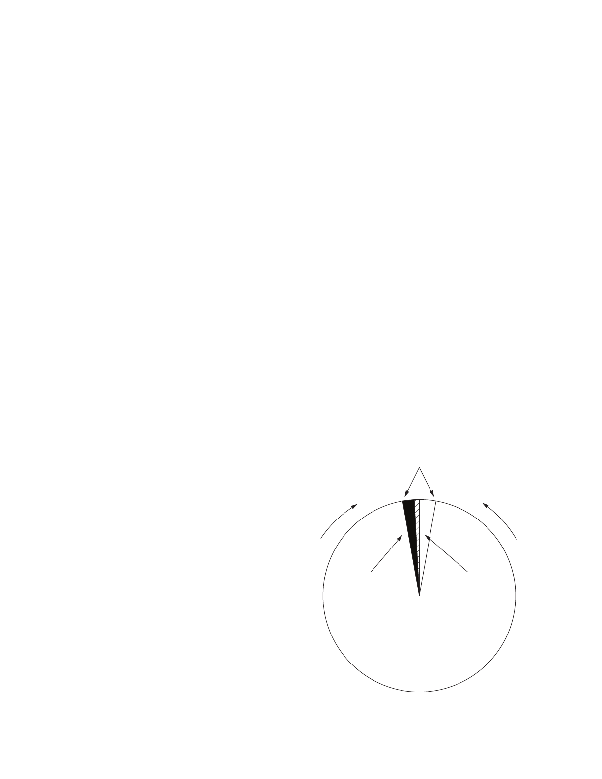
Figure 3 shows the proportional pulse control character-
istic when the GF > BF (antimotoring) feature is enabled.
Figure 4 shows the control characteristic when the
GF > BF feature is disabled.
At zero slip, the generator angle will not rotate into phase
with the power system and a close cannot occur. When
GF > BF is not enabled, zero slip is inside the control
dead band, and no correction pulses will be sent to the
governor to change the slip rate off of zero. Figure 4
shows that the proportional pulse characteristic is modi-
fied by addition of a dead-scope band. If the frequency is
within the dead-scope band of ±20 mHz, a frequency
raise correction pulse will be output to move the slip rate
off of zero.
The following user settings define the control
characteristic:
➤Slip allowed (hertz)
➤Pulse width (seconds) (fixed pulse mode)
➤Proportional pulse slope (seconds/hertz) (propor-
tional pulse mode)
➤Pulse interval (seconds)
➤Enable/disable GF > BF
The pulse interval defines the time between the rising
edges of consecutive correction pulses. This time should
be greater than the settle time of the generator frequency
after each correction pulse.
The width of each correction pulse is proportional to the
deviation of the frequency from the center of the correc-
tion dead band when Proportional Pulse Mode is
enabled. As the frequency approaches the center of the
dead band, the correction pulses become shorter to pre-
vent hunting.
When GF > BF is enabled, the control ensures that the
allowable slip is positive (generator frequency greater
than bus frequency) so that power flow is out of the gen-
erator upon initial synchronization. This feature is rec-
ommended for applications that have prime movers with
extremely sensitive reverse power protection. The center
of the dead band is offset in the positive direction from
zero slip by one half of the slip allowed setting.
The correction dead band is fixed with a 20 percent mar-
gin inside the slip allowed synchronism acceptance set-
ting.