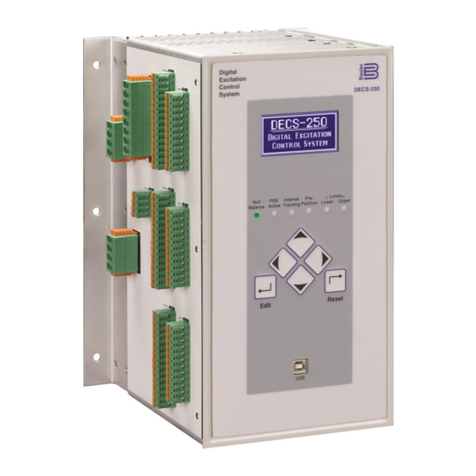
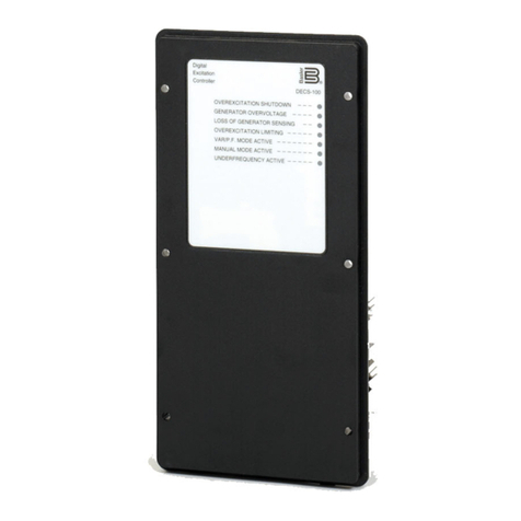
Basler DECS-100 User manual

Publication: 9 2875 00 991
Revision: B 08/01
INSTRUCTION MANUAL
for
DECS-100
Digital Excitation Control System

DECS-100 Introduction i
INTRODUCTION
This instruction manual provides information about the operation and installation of the DECS-100
Digital Excitation Control System. To accomplish this, the following information is provided.
General Information and Specifications
Human-Machine Interface
Functional Description
Installation
BESTCOMS Communication Software
Installation and Troubleshooting
WARNING!
Toavoidpersonalinjuryorequipmentdamage,onlyqualifiedpersonnelshould
perform the procedures in this manual.
Lethal voltage is present at the rear panel when the unit is energized. Rear
panel connections should be made only when the unit is de-energized.
CAUTION
The Manual mode excitation level must be evaluated prior to enabling this
feature. If the level of excitation current is inappropriate for the generator,
severe damage to the generator may occur.
Improper PID numbers will result in poor system performance or system
damage.
Before uploading a settings file, remove operating power from the DECS-100,
disconnect the field wiring from terminals F+ and F–, and re-apply operating
power to the DECS-100.
Before uploading a settings file, remove operating power from the DECS-100,
disconnect the field wiring from terminals F+ and F–, and re-apply operating
power to the DECS-100.
NOTE
Be sure that the DECS-100 is hard-wired to earth ground with no smaller than
12AWGcopperwireattachedtothegroundterminalontherearoftheunitcase.
When the unit is configured in a system with other devices, it is recommended
to use a separate lead to the ground bus from each unit.

DECS-100 Introductionii
First Printing: March 2001
Printed in USA
© 2001, Basler Electric, Highland, IL 62249 USA
August 2001
It is not the intention of this manual to cover all details and variations in equipment, nor does this
manual provide data for every possible contingency regarding installation or operation. The
availability and designof all features and options are subject to modification without notice. Should
further information be required, contact Basler Electric.
BASLER ELECTRIC
ROUTE 143, BOX 269
HIGHLAND, IL, 62249 USA
http://www.basler.com, [email protected]
PHONE 618-654-2341 FAX 618-654-2351
CONFIDENTIAL INFORMATION
ofBasler Electric,Highland, IL.Itis loaned for confidential use, subjectto return
on request, and with the mutual understanding that it will not be used in any
manner detrimental to the interest of Basler Electric.

DECS-100 Introduction iii
MANUAL REVISION HISTORY
The following information provides a historical summary of the changes made to the DECS-100
Instruction Manual (9 2875 00 991). Revisions are listed in reverse chronological order.
Manual Version,
ECO, and Date Change
Rev B, 14282, 08/01 Added
Embedded Software
subsection to Section 5,
BESTCOMS
Software for the Windows Operating System
. Corrected various
minor errors throughout the manual.
Rev A, 12623, 03/01 In Section 5,
BESTCOMS Software for the Windows® Operating
System
and Section 6,
BESTCOMS Software for the Palm OS®
Platform
, Step 2 of
Installing BESTCOMS
was revised to reflect the
addition of an auto-start utility for the DECS-100 CD-ROM.
Rev None, 03/01 Initial release

DECS-100 Introductioniv

DECS-100 Introduction v
CONTENTS
Adetailedtableofcontentsisprovidedatthestartofeachmanualsection.Themanualsectionsare
ordered as follows.
Section 1 General Information ............................................. 1-1
Section 2 Human-Machine Interface ........................................ 2-1
Section 3 Functional Description ........................................... 3-1
Section 4 Installation .................................................... 4-1
Section 5 BESTCOMS Software for the Windows®Operating System ............. 5-1
Section 6 BESTCOMS Software for the Palm OS®Platform ..................... 6-1
Section 7 Maintenance and Troubleshooting ................................. 7-1

DECS-100 General Information i
SECTION 1 • GENERAL INFORMATION
TABLE OF CONTENTS
SECTION 1 • GENERAL INFORMATION ............................................... 1-1
GENERAL ..................................................................... 1-1
FEATURES .................................................................... 1-1
MODEL AND STYLE NUMBER DESCRIPTION ....................................... 1-1
General ................................................................... 1-1
Style Number .............................................................. 1-1
SPECIFICATIONS .............................................................. 1-2
Operating Power ......................................................... 1-2
Generator Voltage Sensing ................................................. 1-2
Generator Current Sensing ................................................. 1-2
Bus Voltage Sensing (Optional) ............................................. 1-2
Accessory Input .......................................................... 1-2
Communication Port ...................................................... 1-2
Contact Input Circuits ..................................................... 1-2
Common Alarm Output .................................................... 1-3
Field Output ............................................................. 1-3
AVR Operating Mode ..................................................... 1-3
FCR (Manual) Operating Mode .............................................. 1-3
Var Operating Mode (Optional) .............................................. 1-3
PF Operating Mode (Optional) .............................................. 1-3
Parallel Compensation .................................................... 1-3
Field Overvoltage Protection ................................................ 1-3
Field Overcurrent Protection ................................................ 1-3
Generator Overvoltage Protection ............................................ 1-3
Soft-Start Function (AVR Mode Only) ......................................... 1-3
Voltage Matching ......................................................... 1-3
Metering (BESTCOMS) .................................................... 1-3
Environment ............................................................. 1-4
Type Tests .............................................................. 1-4
Physical ................................................................ 1-4
UL Recognition .......................................................... 1-4
CSA Certification ......................................................... 1-4
CE Compliance .......................................................... 1-4
Patent ................................................................. 1-4
Figures
Figure 1-1. DECS-100 Style Chart ..................................................... 1-2
Figure 1-2. Typical V/Hz Curves ....................................................... 1-3

DECS-100 General Information 1-1
SECTION 1 • GENERAL INFORMATION
GENERAL
The Basler Digital Excitation Control System (DECS-100) is an electronic, solid-state, microprocessor based
control device. The DECS-100 regulates the output voltage of a brushless, ac generator by controlling the
current into the generator exciter field. Input power to the DECS-100 can be from a multi-pole,
high-frequency, permanent magnet generator (PMG) or from the generator output when used as a
conventional, shunt-excited, excitation system.
The DECS-100 is supplied in an encapsulated package designed for behind-the-panel mounting. The
DECS-100 is held in place by thread-forming screws that thread into its plastic shell. Front panel indicators
(LEDs) annunciate DECS-100 status and system conditions. DECS-100 connections are made through
quarter-inch, quick-connect terminals on the rear panel. A 9-pin DB-9 type connector on the rear panel
provides communication between the DECS-100 and an IBM compatible PC.
FEATURES
DECS-100 units have the following features and capabilities.
CFour control modes: automatic voltage regulation (AVR), manual or field current regulation (FCR),
power factor (PF) regulation, and reactive power (var) regulation.
CProgrammable stability settings.
CSoft start and voltage buildup control with an adjustable ramp in AVR control mode.
COverexcitation (OEL) limiting in AVR, var, and PF control modes.
CUnderfrequency (volts/hertz) regulation.
CThree-phase or single-phase generator voltage (RMS ) sensing/regulation in AVR mode.
CSingle-phase bus voltage (RMS ) sensing.
CSingle-phase generator current sensing for metering and regulation purposes.
CField current and field voltage sensing.
COne analog input for proportional remote control of the setpoint.
CFive contact sensing inputs for system interface.
COne common output relay for alarm indication and trip functions.
CFour protection functions (field overvoltage, field overcurrent, generator overvoltage, and loss of
sensing).
CGenerator paralleling with reactive droop compensation and reactive differential compensation.
CRear RS-232 communication port for personal computer communication using BESTCOMS
Windows® based software for fast, user-friendly, setup and control.
MODEL AND STYLE NUMBER DESCRIPTION
General
DECS-100 electrical characteristics and operational features are defined by a combination of letters and
numbers that make up the style number. The model number, together with the style number, describe the
options included in a specific device, and appear on a label affixed to the rear panel. Upon receipt of a
DECS-100, be sure to check the style number against the requisition and the packing list to ensure that they
agree.
Style Number
Style number identification chart Figure 1-1 defines the electrical characteristics and operational features
available in the DECS-100.

DECS-100 General Information1-2
Figure 1-1. DECS-100 Style Chart
For example, if the style number was A15, the device would have the following characteristics and operating
features.
A.... Novar or power factor control
1 .... Voltage matching
5 .... 5ampere CT secondary
SPECIFICATIONS
DECS-100 electrical and physical specifications are listed in the following paragraphs.
Operating Power
Three-Phase: 200 to 250 VL-L
Single-Phase: 88 to 110 Vac
Frequency Range: 50 to 400 Hz
Burden: 650 VA
Terminals: 3, 4, 5
Generator Voltage Sensing
Type: 1-phase/3-phase, 4 ranges
Burden: <1 VA per phase
Terminals: E1, E2, E3
50 Hertz Sensing
Range 1: 100 Vac (85 to 132 Vac)
Range 2: 200 Vac (190 to 220 Vac)
Range 3: 400 Vac (380 to 440 Vac)
Range 4: N/A
60 Hertz Sensing
Range 1: 120 Vac (85 to 132 Vac)
Range 2: 240 Vac (170 to 264 Vac)
Range 3: 480 Vac (340 to 528 Vac)
Range 4: 600 Vac (540 to 660 Vac)
Generator Current Sensing
Type: 1-phase (B-phase), 50/60 Hz
Style X1X: 1 Aac maximum continuous
Style X5X: 5 Aac maximum continuous
Burden: <0.1 VA
Terminals: CT1, CT2
Bus Voltage Sensing (Optional)
Type: 1-phase, 4 ranges
Burden: <1 VA per phase
Terminals: B1, B3
Bus Voltage Sensing (Optional)–continued
50 Hertz Sensing
Range 1: 100 Vac (85 to 132 Vac)
Range 2: 200 Vac (190 to 220 Vac)
Range 3: 400 Vac (380 to 440 Vac)
Range 4: N/A
60 Hertz Sensing
Range 1: 120 Vac (85 to 132 Vac)
Range 2: 240 Vac (170 to 264 Vac)
Range 3: 480 Vac (340 to 528 Vac)
Range 4: 600 Vac (540 to 660 Vac)
Accessory Input
Voltage Range: –3 Vdc to +3 Vdc
Setpoint Range: –30% to +30% shift
Burden: 1 kS
Terminals: A, B
Communication Port
Interface: Full duplex RS-232
Connection: Rear panel DB-9 connector
Baud: 4800
Data Bits: 8
Parity: None
Stop Bit: 1
Contact Input Circuits
Type: Dry Contact
Interrogation Voltage: 13 Vdc
Terminal Assignments for Standard Functions
Unit/Parallel Control: 52L, 52M
Raise: 6U, 7
Lower: 6D, 7

DECS-100 General Information 1-3
Figure 1-2. Typical V/Hz Curves
Contact Input Circuits–continued
Terminal Assignments for Optional Functions
Var/PF Enable: 52J, 52K
Voltage Matching: VM, VMC
Common Alarm Output
Type: Form A
Rated Load: 7 Aac/Adc continuous
Make: 30 Aac/Adc, carry for 0.2 sec
Break: 7 Aac/0.1 Adc
Operating Voltage: 240 Vac/250 Vdc maximum
Terminals: AL1, AL2
Field Output
Field Resistance: 5 Sminimum
Terminals: F+, F–
Continuous Rating: 63 Vdc, 7 Adc
10 Second Forcing Rating
200 Vac Power Input: 135 Vdc, 15 Adc
110 Vac Power Input: 90 Vdc, 10 Adc (9 Sfield)
75 Vdc, 15 Adc (5 Sfield)
AVR Operating Mode
Adjustment Range: See Generator Voltage Sensing
Voltage Regulation: ±0.25% over load range at
rated power factor and
constant generator frequency.
±0.5% with 3-phase sensing
and shunt power at 40% THD
of the voltage waveform (due to
a 6 SCR load).
Temperature Drift: ±0.5% for a 40EC change
V/Hz Characteristic: Slope from 0 to 3PU is adjust-
able in 0.01PU increments.
Transition (Corner) frequency
is adjustable from 40 to 65 Hz.
See Fig. 1-2 for V/Hz curves.
Response Time: Within 1 cycle
FCR (Manual) Operating Mode
Adjustment Range: 0 to 7 Adc
Increment: 0.1 A
Var Operating Mode (Optional)
Adjustment Range: 100% to –100%
Increment: 0.1%
PF Operating Mode (Optional)
Adjustment Range: 0.6 lead to 0.6 lag
Increment: 0.001
Parallel Compensation
Modes: Reactive Droop and Reactive
Differential (cross-current)t
Droop Adjust Range: 0 to 10%
Increment: 1%
tBurden can exceed 1 VA if external resistors are
added to the CT circuit.
Field Overvoltage Protection
Pickup Range: 0 to 250 Vdc
Time Delay: 10 seconds (fixed)
Field Overcurrent Protection
Pickup
Range: 0 Adc to 15 Adc
Increment: 0.001 Adc
Time Delay
Range: 0 to 10 seconds
Increment: 1 second
Generator Overvoltage Protection
Pickup 100% to 120% of system
voltage setting
Increment: 1.0%
Time Delay: 0.75 seconds (fixed)
Soft-Start Function (AVR Mode Only)
Time Adjust Range: 1 to 7,200 seconds
Increment: 1 second
Voltage Matching
Accuracy: Generator rms voltage is
matched with the bus rms
voltage to within ±0.5% of the
generator voltage.
Time Adjustment
Range: 0 to 300 seconds
Increment: 0.01 seconds
Metering (BESTCOMS)
Generator Voltage
Range: 10 V to 79 kV
Accuracy: ±0.5% (at 25EC)
Generator Current
Range: 0.04 to 1,000 A (1 A CTs)
0.1 to 5,000 A (5 A CTs)
Accuracy: ±0.5% (at 25EC)

DECS-100 General Information1-4
Metering (BESTCOMS)–continued
Frequency
Range: 40 to 65 Hz
Accuracy: ±0.2 Hz (at 25EC)
Field Voltage
Range: 0 to 200 V
Accuracy: ±5.0% (at 25EC)
Field Current
Range: 0 to 20 A
Accuracy: ±0.5% (at 25EC)
Bus Voltage
Range: 10 V to 79 kV
Accuracy: ±0.5% (at 25EC)
Auxiliary DC Input
Range: –3 V to +3 V
Accuracy: ±0.5% (at 25EC)
Power (Apparent, Real, and Reactive
Range: 0 to 99 MVA, MW, Mvar
Accuracy: ±3.0% (at 25EC)
Power Factor
Range: –1.0 to –0.6, +0.6 to +1.0
Accuracy: ±0.02 at rated current (25EC)
Phase Angle
Range: 0 to 360 degrees
Accuracy: ±2.0 degrees (at 25EC)
Environment
Operating Temperature
DECS-100: –40EC to 70EC
(–40EF to 158EF)
Storage Temperature
DECS-100: –40EC to 85EC
(–40EF to 185EF)
CD-ROM: 0EC to 50EC
(32EF to 122EF)
Type Tests
Shock: 20 Gs in 3 perpendicular
planes
Vibration: 1.2 Gs at 5 to 26 Hz
0.914 mm (0.036") double
amplitude at 27 to 52 Hz
5 Gs at 53 to 500 Hz
Salt Fog: Tested per MIL-STD-810E
Physical
Weight
Unit: 1.10 kg (2.42 lb)
Shipping: 1.31 kg (2.88 lb)
Shipping Carton Dimensions (W x H x D)
Single Unit: 299 mm x 79 mm x 146 mm
(11.75" x 3.125" x 5.75")
48 Units: 841 mm x 653 mm x 352 mm
(33.13" x 25.69" x 13.88")
UL Recognition
Recognized per Standard 508, UL File E97035
CSA Certification
Certified per Standard CAN/CSA-C22.2, Number 14-
95, CSA File LR23131-139
CE Compliance
Emissions
CISPR11/EN55011, Level A
Electrostatic Discharge (ESD)
IEC 1000-4-2/EN 61000-4-2, Level B
Radiated Susceptibility
IEC 1000-4-3/EN 61000-4-3, Level A
Electrical Fast Transient
IEC 1000-4-4/EN 61000-4-4, Level B
Radio Frequency–Conducted
IEC 1000-4-6/EN 61000-4-6, Level A
Power Frequency–Magnetic
IEC 1000-4-8/EN 61000-4-8, Level A
Dielectric
IEC 255
Patent
U.S. Patent Number 5294879

DECS-100 Human-Machine Interface i
SECTION 2 • HUMAN-MACHINE INTERFACE
TABLE OF CONTENTS
SECTION 2 • HUMAN-MACHINE INTERFACE ........................................... 2-1
GENERAL ................................................................. 2-1
FRONT PANEL INDICATORS ................................................. 2-1
COMMUNICATION PORT ..................................................... 2-2
Figures
Figure 2-1. DECS-100 Front Panel Indicators ............................................ 2-1
Figure 2-2. DECS-100 Communication Port Location ...................................... 2-2
Tables
Table 2-1. DECS-100 Front Panel Indicator Descriptions ................................... 2-1

DECS-100 Human-Machine Interface 2-1
Figure 2-1.
DECS-100 Front Panel Indicators
SECTION 2 • HUMAN-MACHINE INTERFACE
GENERAL
The DECS-100 human-machine interface (HMI) consist of front panel indicators and a rear panel
communication port.
FRONT PANEL INDICATORS
DECS-100 front panel indicators consist of seven red LEDs. Figure 2-1 shows the front panel indicators for
the DECS-100. Table 2-1 describes the function of each front panel indicator.
Table 2-1. DECS-100 Front Panel Indicator Descriptions
Indicator Description
Overexcitation Shutdown This LED lights when the Overexcitation Protection feature is
enabled and the field voltage exceeds 100 Vdc for 10 seconds. The
DECS-100 will shutdown when an overexcitation condition is
detected. The Overexcitation Shutdown LED will light for 5 seconds
when the DECS-100 is powered up following an overexcitation
shutdown.
Generator Overvoltage This LED lights when generator output voltage exceeds the
adjustable setpoint for 0.75 seconds. The DECS-100 will shutdown
when a generator overvoltage condition is detected. The Generator
Overvoltage LED will light for 5 seconds when the DECS-100 is
powered up following a generator overvoltage shutdown.

Indicator Description
DECS-100 Human-Machine Interface
2-2
Figure 2-2.
DECS-100
Communication Port Location
Loss of Generator Sensing This LED lights when a loss of generator sensing voltage is detected.
Depending on the protective action selected, the DECS-100 will
either shutdown or transfer to Manual mode. The Loss of Generator
Sensing LED will flash for 5 seconds when the DECS-100 is
powered up following a loss of generator sensing shutdown.
Overexcitation Limiting This LED lights when the field current exceeds the programmed
overexcitation limit. It stays lit until the overexcitation condition
ceases or the overexcitation time delay expires and the DECS-100
shuts down. The Overexcitation Limiting LED will flash for 5 seconds
when the DECS-100 is powered up following an overexcitation
limiting shutdown.
Var/P.F. Mode Active This LED lights to indicate that the DECS-100 is operating in the
optional Var or Power Factor mode of control. Var/Power Factor
control is enabled through BESTCOMS software and when the 52J/K
contact input is open.
Manual Mode Active This LED lights when the DECS-100 is operating in Manual mode.
Manual mode is enabled through BESTCOMS software.
Underfrequency Active This LED lights when the generator frequency decreases below the
underfrequency setpoint and the DECS-100 is regulating on the
selected volts per hertz curve.
COMMUNICATION PORT
The communication port is located on the rear panel and
consists of a female RS-232 (DB-9) connector. The
communication port serves as an interface for programming
(setup) of the DECS-100. Figure 2-2 illustrates the location of
the communication port.
Programming requires a standard 9-pin serial communication
cable connected between the DECS-100 and an IBM-
compatible PC or handheld computer operating with
BESTCOMS software. BESTCOMS software is a Windows®
98/NT based communication software package that is
supplied with the DECS-100. A detailed description of
BESTCOMS software is provided in Section 5, BESTCOMS
Software.
WARNING!
Lethal voltage is present at the rear panel when the unit
is energized. Rear panel connections should be made
only when the unit is de-energized.

DECS-100 Functional Description i
SECTION 3 • FUNCTIONAL DESCRIPTION
TABLE OF CONTENTS
SECTION 3 • FUNCTIONAL DESCRIPTION ............................................. 3-1
INTRODUCTION ............................................................... 3-1
DECS-100 FUNCTION BLOCKS ................................................... 3-1
Analog Input Circuits ......................................................... 3-1
Bus Voltage ............................................................. 3-1
Generator Voltage ........................................................ 3-2
Phase B Line Current ..................................................... 3-2
Accessory Input (Auxiliary Adjust) ........................................... 3-2
Field Voltage (VFIELD) ...................................................... 3-2
Field Current (IFIELD) ....................................................... 3-2
Contact Input Circuits ........................................................ 3-2
Raise .................................................................. 3-2
Lower .................................................................. 3-2
Var/Power Factor Control (52J/K) Option ...................................... 3-3
Parallel Generator Compensation (52L/M) ..................................... 3-3
Voltage Matching Control Option ............................................ 3-3
RS-232 Communication Port ................................................... 3-3
Microprocessor ............................................................. 3-3
Power Input Stage ........................................................... 3-3
Power Supply ............................................................... 3-3
Power Amplifier Stage ........................................................ 3-3
Front Panel Indicators ........................................................ 3-3
Relay Output ............................................................... 3-3
DECS-100 OPERATING FEATURES ............................................... 3-4
Operating Modes ............................................................ 3-4
Automatic Voltage Regulation Mode ......................................... 3-4
Manual Mode ............................................................ 3-4
Var Control Mode (Optional) ................................................ 3-4
Power Factor Control Mode (Optional) ........................................ 3-4
Reactive Droop Compensation ................................................. 3-4
Underfrequency ............................................................. 3-5
Protection .................................................................. 3-5
Overexcitation Shutdown (Field Voltage) ...................................... 3-5
Generator Overvoltage Shutdown ........................................... 3-5
Loss of Generator Sensing Shutdown or Transfer ............................... 3-5
Overexcitation Limiting (Field Current) ........................................ 3-6
Soft Start .................................................................. 3-6
Voltage Matching (Optional) ................................................... 3-6
Figures
Figure 3-1. Simplified Block Diagram ................................................... 3-1

DECS-100 Functional Description 3-1
Figure 3-1.
Simplified DECS-100 Block Diagram
SECTION 3 • FUNCTIONAL DESCRIPTION
INTRODUCTION
This section describes how the DECS-100 functions and explains its operating features. To ease
understanding, DECS-100 functions are illustrated in the block diagram of Figure 3-1. A detailed description
of each function block is provided in the paragraphs under the heading of
DECS-100 Function Blocks
.
DECS-100 operating features include four operating modes, four protective functions, startup provisions,
reactive droop compensation, underfrequency compensation, and optional voltage matching. A detailed
description of each operating feature is provided in the paragraphs under the heading of
DECS-100 Operating
Features
.
DECS-100 FUNCTION BLOCKS
The following paragraphs describe each of the function blocks illustrated in Figure 3-1. The function of each
block is explained along with the operation of all function block inputs and outputs.
Analog Input Circuits
Seven analog voltage and current inputs may be sensed and brought to the DECS-100 input.
Bus Voltage
C-phase and A-phase bus voltages are monitored at terminals B3 and B1 on units that include Voltage
Matching. Nominal voltages of up to 600 Vac may be sensed at these terminals. Voltage monitored at this
input is scaled and conditioned before being applied to the input of the analog-to-digital converter (ADC). This
bus voltage signal applied to the ADC is used to calculate the RMS value of the bus voltage across phases
C and A (Bus VC-A).

DECS-100 Functional Description3-2
Generator Voltage
Generator voltage is monitored at terminals E1 (A-phase), E2 (B-phase), and E3 (C-phase). Nominal voltages
of up to 600 Vac may be sensed at these terminals. Voltage applied to these inputs is scaled and conditioned
before being applied to the input of the ADC. The voltage signal from phase C and A (VC-A) of the generator
is used by the ADC to calculate the RMS value of generator voltage across phases C and A. Likewise, the
voltage signal from phase C and B (VC-B) of the generator is used by the ADC to calculate the RMS value of
generator voltage across phases C and B. The RMS value of generator phase B to phase A voltage (VB-A)
is calculated by the microprocessor from the phase C to phase A signal (VC-A)and the phase C to phase B
(VC-B) signal.
Additionally, the generator phase C to phase A (VC-A) signal is applied to a filtered zero cross detector circuit.
This signal is applied to the microprocessor and is used to calculate generator frequency.
Phase B Line Current
The phase B line current (IB) signal is developed through a customer supplied current transformer (CT) and
monitored through terminals CT1 and CT2. Depending on the option selected, current up to 1 ampere (style
number xx1) or 5 amperes (style number xx5) rms may be monitored at these terminals. The current
monitored at these terminals is scaled and conditioned by an internal current transformer and active circuitry
for use by the ADC. The signal applied to the ADC is used to calculate the rms value of phase B line current.
Additionally, the phase angle between phase B line current and phase C to phase A generator voltage is
calculated for use during Droop and Var/Power Factor operation.
Accessory Input (Auxiliary Adjust)
This input allows adjustment of the DECS-100 regulation setpoint by the application of a positive or negative
dc voltage across terminals A and B. Voltage of up to +3 Vdc may be applied to this input. The circuit induces
a 1,000-ohm burden on the dc source. The Application of a +3 Vdc signal corresponds to a +30 percent
change in setpoint.
Field Voltage (V
FIELD
)
Voltage across the regulator field output terminals, F+ and F–, is monitored, scaled, and conditioned
before being applied to the ADC. This signal is used to calculate the dc value of field voltage for use in
system protection.
Field Current (I
FIELD
)
Current through the main power output switch is converted to a proportional voltage level. This voltage signal
is scaled and conditioned before being applied to the input of the ADC. The result is used to calculate the dc
value of field current for use in the Manual mode of operation as well as protection of the system.
Contact Input Circuits
Five contact input circuits powered from an internal 13 Vdc supply provide input control from user-supplied
contacts.
Raise
Closing a contact across terminals 6U and 7 causes the active operating setpoint to increase. This function
is active as long as the contact is closed.
Lower
Closing a contact across terminals 6D and 7 causes the active operating setpoint to decrease. This function
is active as long as the contact is closed.

DECS-100 Functional Description 3-3
Var/Power Factor Control (52J/K) Option
Closing a contact across terminals 52J and 52K disables var/power factor control. An open contact enables
the DECS-100 to control the generator reactive power in either the var or the power factor mode. The contact
has no effect when this function is not enabled in the software. For more information, refer to the Parallel
Generator Compensation (52L/M) contact input.
Parallel Generator Compensation (52L/M)
Closing a contact across terminals 52L and 52M disables parallel operation. An open contact enables parallel
operation and the DECS-100 operates in reactive droop compensation mode.
If the Var/Power Factor Control option is present and is enabled in the software, the 52J/K input has priority.
Therefore, if the 52J/K and the 52L/M inputs are both open, the system operates in var/power factor mode.
Voltage Matching Control Option
If the Voltage Matching option is enabled in the software, closing a contact across terminals VM and VMC
causes the DECS-100 to operate in the voltage matching mode. An open contact disables voltage matching.
RS-232 Communication Port
The communication port provides the interface for user programming (setup) of the DECS-100. Connection
is made to the female RS-232 (DB-9) connector with a user-supplied, standard 9-pin cable. The
communication port is optically isolated and is powered from a transformer-isolated supply.
Microprocessor
The microprocessor is the heart of the DECS-100 and performs measurement, computation, control, and
communication functions by the use of its embedded programming and the nonvolatile settings stored in its
memory.
Power Input Stage
Input power applied to terminals 3, 4, and 5 is rectified and filtered before being applied to the power amplifier
and the power supply. Input power may be single-phase or three-phase in the range of 88 to 250 Vac at a
frequency of 50 to 400 hertz.
The input power source should be properly fused for the application.
Power Supply
The internal switch-mode power supply receives power from the power input stage and supplies power at
the required dc voltage levels to the internal circuitry of the DECS-100.
Power Amplifier Stage
The power amplifier receives power from the power input stage and supplies a controlled amount of power
to the exciter field via terminals F+ and F–. The amount of power supplied to the exciter field is based on
gating pulses received from the microprocessor. The power amplifier uses a solid state power switch to
provide the required power to the exciter field. Power amplifier output to the field is rated up to 63 Vdc at 7
Adc continuous and 135 Vdc at 15 Adc for 10 seconds.
Front Panel Indicators
Seven front panel LED indicators light to indicate various protective functions and operating modes. Section
2,
Human-Machine Interface
provides more information about the front panel indicators.
Relay Output
A common alarm output contact is provided through terminals AL1 and AL2. This normally open, form A
contact annunciates alarm or trip conditions. The relay output is non-latching.

DECS-100 Functional Description3-4
DECS-100 OPERATING FEATURES
The following paragraphs describe the characteristics of each DECS-100 operating feature.
Operating Modes
The DECS-100 provides up to four modes of operation selectable through BESTCOMS software. Automatic
voltage regulation mode and Manual mode are standard features. Var and Power Factor modes are an
option.
Automatic Voltage Regulation Mode
In Automatic Voltage Regulation (AVR) mode, the DECS-100 regulates rms generator output voltage. This
is accomplished by sensing generator output voltage and adjusting dc output excitation current to maintain
voltage at the regulation setpoint. The regulation setpoint is adjusted by the Raise and Lower contact inputs,
the Accessory input, or through BESTCOMS software. The regulation point may also be modified by the
Droop function or the Underfrequency function under certain conditions.
Manual Mode
In Manual mode, also known as Field Current Regulation (FCR) mode, the DECS-100 maintains dc excitation
current at a set level. The current-level setpoint is adjustable from 0 to 7 Adc in 0.1 Adc increments by the
Raise and Lower contact inputs, the optional Accessory input, or through BESTCOMS software.
Var Control Mode (Optional)
In Var Control mode, the DECS-100 maintains generator vars (volt-amperes, reactive) at a set level when
paralleling with an infinite bus. The DECS-100 calculates generator vars by using the sensed generator
output voltage and current quantities. It then adjusts the dc excitation current to maintain vars at the setpoint.
Var control is enabled and disabled through BESTCOMS software. When the software is turned on, var
control is enabled or disabled through the Var/Power Factor Control (52J/K) contact input circuit. The var
setpoint is adjustable from 100 percent absorb to 100 percent generate through the Raise and Lower contact
inputs, the optional Accessory input, or through BESTCOMS software.
Power Factor Control Mode (Optional)
In Power Factor Control mode, the DECS-100 maintains generator power factor at a set level when
paralleling with an infinite bus. The DECS-100 calculates generator power factor using the sensed generator
output voltage and current quantities and then adjusts the dc excitation current to maintain power factor at
the setpoint. Power factor control is enabled or disabled through BESTCOMS software. When the software
is turned on, it is enabled or disabled through the Var/Power Factor Control (52J/K) contact input circuit. The
power factor setpoint is adjustable between 0.6 lag and 0.6 lead through the Raise and Lower contact inputs,
the optional Accessory input, or through BESTCOMS software.
Reactive Droop Compensation
The DECS-100 provides a reactive droop compensation feature to assistin the sharingofreactive load during
parallel generator operation. When this feature is enabled, the DECS-100 calculates the reactive portion of
the generator load using the sensed generator output voltage and current quantities and then modifies the
voltage regulation setpoint accordingly. A unity power factor generator load results in almost no change in
generator output voltage. A lagging power factor generator load (inductive) results in a reduction of generator
output voltage. A leading power factor generator load (capacitive) results in an increase of generator output
voltage. Droop is adjustable up to 10 percent with rated, nominal B-phase line current (1 ampere or 5
amperes applied through terminals CT1 and CT2) and 0.8 power factor. The droop feature is enabled and
disabled through the Parallel Generator Compensation contact input circuit (terminals 52L and 52M). Droop
is also disabled when operating in var or power factor control modes.
CAUTION
The Manual mode excitation level must be evaluated prior to enabling this
feature. If the level of excitation current is inappropriate for the generator,
severe damage to the generator may occur.

DECS-100 Functional Description 3-5
Underfrequency
When generator frequency drops below the selected knee frequency setpoint, the voltage setpoint is
automatically adjusted by the DECS-100 so that generator voltage follows the selected PU (per unit) V/Hz
curve. When operating on the selected PU V/Hz curve, the UNDERFREQUENCY ACTIVE indicator lights
on the front panel and in BESTCOMS. Underfrequency control is disabled below 12 hertz. The knee
frequency is adjustable from 40 to 65 hertz in 0.1 hertz increments and the PU V/Hz curve may be set at a
slope of 0 to 3 in 0.01 steps through BESTCOMS software. A slope of 0 effectively disables the
underfrequency function. The DECS-100 has a minimum regulation point of approximately 30 percent of the
nominal setpoint.
Protection
The DECS-100 includes four protective functions: overexcitation shutdown, generator overvoltage shutdown,
loss of generator sensing shutdown or transfer, and overexcitation limiting. Each function has a
corresponding front panel indicator that lights when the function is active. An active function is also
annunciated through BESTCOMS software.
Overexcitation Shutdown (Field Voltage)
This function is enabled or disabled through BESTCOMS software. When enabled, if field voltage exceeds
the adjustable field overvoltage setpoint for 10 seconds, the OVEREXCITATION SHUTDOWN indicator on
the front panel and in BESTCOMS lights, the relay output closes, and the DECS-100 shuts down. When the
DECS-100 is powered up following an overexcitation shutdown, the OVEREXCITATION SHUTDOWN
indicator will light for 5 seconds. The Field Overvoltage setpoint is adjustable from zero to 250 Vdc in integer
steps.
Generator Overvoltage Shutdown
The DECS-100 monitors the sensed generator output voltage. If it exceeds the adjustable Generator
Overvoltage setpoint of the nominal setpoint for 0.75 seconds, the GENERATOR OVERVOLTAGE indicator
lights on the front panel HMI and in BESTCOMS, the relay output closes, and the DECS-100 shuts down.
When the DECS-100 is powered up following a generator overvoltage shutdown, the GENERATOR
OVERVOLTAGE indicator will light for 5 seconds. The Generator Overvoltage setpoint is adjustable from 100
to 120 percent in integer steps.
Loss of Generator Sensing Shutdown or Transfer
The DECS-100 monitors the sensed generator output voltage and takes protective action if a loss of sensing
voltage is detected. A loss of sensing voltage is detected during the following conditions.
The sensed voltage is less than 50 percent of the rated voltage (one-phase or three-phase sensing).
A total loss of any phase occurs (three-phase sensing).
The voltage difference between any phase (line-to-line) and the three-phase average exceeds 20
percent of nominal (three-phase sensing).
A time delay of zero to 25 seconds is adjustable through BESTCOMS software. This delays the protective
action in order to allow field forcing in applications that do not sense B-phase generator current. The default
time delay setting is 10 seconds.
BESTCOMS software allows the selection of one of two protective actions for a loss of sensing. Either a
complete shutdown or a transfer to Manual mode may be selected.
If shutdown is selected and a loss of sensing occurs, the LOSS OF GENERATOR SENSING indicator on
the front panel and in BESTCOMS lights, the relay output closes, and the DECS-100 shuts down after the
adjustable time delay expires. When the DECS-100 is powered up following a loss of generator sensing
shutdown, the LOSS OF GENERATOR SENSING indicator will light for 5 seconds.
If transfer to manual is selected and a loss of sensing occurs, the relay output closes, and the DECS-100
transfers to the Manual mode of operation after the adjustable time delay expires. The DECS-100 will remain
in this mode of operation until power is cycled.
This function is disabled when the frequency decreases below 12 hertz or when a generator short circuit
condition is detected. A generator short-circuit is determined when the B-phase CT current exceeds three
times the per unit value. Loss of sensing shutdown or transfer is not active during the soft-start time.
Other manuals for DECS-100
1
Table of contents
Other Basler Control System manuals
Popular Control System manuals by other brands

David Clark
David Clark u3800 Installation & operation instructions

Kurt
Kurt 3400V Series Operating instructions manual

Beninca
Beninca VE.500 Operating instructions and spare parts catalogue

Savari
Savari STREETWAVE user guide

Dakota Digital
Dakota Digital COMMANDER Series manual

rotork
rotork Paksan P3F Technical manual

Sub-Zero
Sub-Zero Built-in Series Assembly

Roger
Roger B70/2DC Instruction and warnings for the installer

Divetis
Divetis 200-0018 quick start guide

BERGES Electronic
BERGES Electronic ACP 6000 operating instructions

eqss
eqss OverWatch Dingli S03-ACE Series installation manual

DoorKing
DoorKing 1610 installation guide