TechnoAP APU101 User manual

Manual APU101
2
TechnoAP Co., Ltd.
-Table of contents -
1. Overview...................................................................................................................................................................................... 5
2. Specifications............................................................................................................................................................................... 6
3. Appearance................................................................................................................................................................................. 8
4. Setup..........................................................................................................................................................................................11
4.1. Applicationinstallation......................................................................................................................................................11
4.2. High-voltagepowersupplypolaritycheckandchangemethod.................................................................................11
4.3. Cableconnection..............................................................................................................................................................12
4.4. Networksetup...................................................................................................................................................................13
5. Applicationscreen.....................................................................................................................................................................15
5.1. Startupscreen...................................................................................................................................................................15
5.2. CHtab................................................................................................................................................................................18
5.3. configtab............................................................................................................................................................................26
5.4. histogramtab.....................................................................................................................................................................28
5.5. wavetab.............................................................................................................................................................................31
5.6. HVtab.................................................................................................................................................................................33
6. Initialsetting...............................................................................................................................................................................36
6.1. Preamplifieroutputsignalconfirmation..........................................................................................................................36
6.2. Powerandconnection......................................................................................................................................................36
6.3. Settingexecution...............................................................................................................................................................36
6.4. Analogcoursegainandanalogpolezeroadjustmentofpreamplifieroutputsignal................................................37
6.5. FASTfiltersettings............................................................................................................................................................39
6.6. SLOWfiltersettings..........................................................................................................................................................40
6.7. SLOWthresholdsetting...................................................................................................................................................41
6.8. Signalprocessingbyexternalinputterminal.................................................................................................................42
6.9. Calculationmethodofhalfwidthathalfmaximum(FWHM)FullWidthatHalfMaximum......................................43
7. Measurement............................................................................................................................................................................44
7.1. Initializationsettings..........................................................................................................................................................44
7.2. Measurementstarts..........................................................................................................................................................44
7.3. Measurementstops..........................................................................................................................................................45
8. Conclusion.................................................................................................................................................................................45
8.1. Highvoltageoutputstep-down........................................................................................................................................45
8.2. Applicationsoftwareexit...................................................................................................................................................45
9. File .............................................................................................................................................................................................46
9.1. Histogramdatafile............................................................................................................................................................46
9.2. Listdatefile........................................................................................................................................................................48
10. Troubleshooting....................................................................................................................................................................49
10.1. Connectionerroroccurs...............................................................................................................................................49
10.2. Commanderroroccurs................................................................................................................................................49
10.3. Histogramisnotdisplayed...........................................................................................................................................50

Manual APU101
3
TechnoAP Co., Ltd.
10.4. ChangeIPaddress.......................................................................................................................................................50
11. Gaussfit..................................................................................................................................................................................51
11.1. Startupscreen...........................................................................................................................51
11.2. On-line.......................................................................................................................................53
11.3. Off-line.......................................................................................................................................54
11.4. Notes.........................................................................................................................................55
11.5. End.............................................................................................................................................55
12. Peaksearch...........................................................................................................................................................................56
12.1. Startupscreen...........................................................................................................................56
12.2. On-line.......................................................................................................................................58
12.3. Off-line.......................................................................................................................................59
12.4. Notes.........................................................................................................................................59
12.5. End.............................................................................................................................................60

Manual APU101
4
TechnoAP Co., Ltd.
Safety Precautions / Disclaimer
ThankyouforpurchasingtheproductofTechnoAPCo.,Ltd.(hereinafterreferredtoas "ourcompany").Before
using the product, please read this "Safety Precautions / Disclaimer" and be sure to observe the contents to ensure
correct use.
Even if an accident occurs due to the use of our products, we will not be liable for any damages including
abnormalities of devices, detectors, connected devices and applications, damages caused by failures, and other
secondarydamages.
Prohibited matter
• It cannot be used for applications that require special quality and reliability related to human life and
accidents.
• Please refrain from using the product in places with high temperature, high humidity, and high vibration
(excludingcountermeasures).
• Do not apply more power than rated.
• Do not turn on the board product with other metals in contact withtheboard surface.
Notes
• Turn off the power immediately if there is smoke or abnormal heat generation.
• It may not work properly in a noisy environment.
• Be careful of static electricity.
• Product specifications and related documents are subject to changewithoutnotice.
Warranty conditions
Thewarrantyconditionsfor"ourproducts"areasfollows.
・Period:Oneyearafterpurchase.
・Contents: If theproductbreaksdownduring usewithin the warrantyperiod, itwillbe repairedor replaced.
・Notapplicable:Wedonotguaranteeifthecauseoffailurefallsunderanyofthefollowing.
1. Useotherthantheoriginalusageof"ourproducts"
2. Inadditiontotheabove,causesotherthan"ourcompany"or"ourproducts"(includingforcemajeuresuchas
natural disasters)
3. Consumables,etc.

Manual APU101
5
TechnoAP Co., Ltd.
1. Overview
Digital spectrometer APU101 (hereinafterreferred to as this device) is a digital spectrometer that integrates a high-
voltage power supply, preamplifier power supply, and MCA (multi-channel analyzer) into one. Since it is amulti-channel
analyzer (MCA) equipped with a real-time digital signal processing function (DSP), waveform shaping processing by an
analog circuit is not required, and a very high-speed A / D converter is used to directly digitalize the signal from the
preamplifier. It is converted to and processed by the trapezoidal filter in real time by the pipeline architecture by FPGA.
This provides excellent energy and time resolution and has outstanding stability even at high count rates (100 kcps and
above).
This device can be connected to a personal computer (hereinafter referred to as PC) with a LAN cable, and by
using the attached application APP101 (hereinafter referred to as this application), parameters can be set, data can be
read,andmeasureddatacanbeanalyzedandimported.
Thismanualdescribesthehandlingofthisdeviceandthisapplication.
* This manual describes normal products and may differ from the one you are using depending on the presence or
absence ofoptions,special specifications,andspecificationsofthehigh-voltagepowersupplymodule.
*Thecontentsofthismanualaresubjecttochangewithoutnotice.

Manual APU101
6
TechnoAP Co., Ltd.
2. Specifications
1. AnalogInput
・Numberofchannels 1CH
・Inputrange ±1 V
・Inputimpedence 1kΩ
・Coarsegain ×1,×4, ×10, ×20 Setthevaluefromtheapplication
2. ADC
・Samplingfrequency 100 MHz
・Resolution 14bit
3. MCA
・ADCgain 8192, 4096, 2048, 1024, 512, 256 channel
・Measurementmode Histogram, Wave and List
4. Digitalpulseshaping
・SLOW,Risetime 0.1μs-10μs
・SLOW,Flattoptime 0.1μs –1μs
・DigitalFinegain ×0.333-×1
・DigitalPolezerocancel
・Digital BaselineRestorer
・Digital PileupReject
・LLD, Lower-LevelDiscriminator
・ULD, Upper-LevelDiscriminator
5. Unitpanel,Switch, ButtonandConnector
FRONT
・Unitpowersupply, LEDforEMO
・Emergencystop button
・LEDforHighvoltagepowermonitor
・LEDforDead-timemonitor
・Clearsignalinputconnector * unused
・Clock signalinputconnector
・AUX1and AUX2 signal outputconnector
BACK
・DCpowersupply connector
・F.G terminal
・D-Sub15-pinconnectorforpreamplifierpowersupply
・BNCconnectorforfilterwaveformoutput

Manual APU101
7
TechnoAP Co., Ltd.
・Connectorforpreamplifieroutputsignalinput
・SHVconnectorforhighvoltagepoweroutput
・LEMOcompatibleconnectorforhighvoltagepowershutdown
6. High-voltagepowersupply
*Ifthespecificationsarechanged,themaximumoutputvoltageandcurrentvaluemaydiffer.
・Outputvoltage Positiveelectrodeproperty,negativeelectrodeproperty,
High-Zswitchable,0Vto4000V,±5%,1GΩ load
・Outputimpedence About200 kΩ
・Outputcurrent Max.1mA
・Ripple 20 mVp-p(typ.)
・Supportsautomaticstep-downbydetectingbiasshutdownsignal
7. Preamplifierpowersupply ±12 V,±24V * NIM standardcompliant
8. Communicationinterface RJ45connector,Ethernet 1000Base-T, TCP/IP and UDP
9. Outerdiameter 210 (W)x45 (H) x275 (D) mm *withoutconnectors
10. Weight about1800g
11. Currentconsumption +12V,0.8 A
PowersupplyforPreamplifier,±12V, ±24 V,
*Dependsontheconnectedpreamp
12. PC environment
・OS Windows 7or later,32bitand64bit orlater
・Screenresolution RecommendedaboveHD 1366×768

Manual APU101
8
TechnoAP Co., Ltd.
3. Appearance
Image1 APU101 Front
1. LED EMO (red) Lights during emergency.
POS (orange) Lights when the HV is positive.
NEG (green) Lights when the HV is negative.
If both POS and NEG are off, it is in the high-Z state. It blinks long when
stepping up, blinks shortly when stepping down, and lights up when the set
voltage is reached.
2. RESET This button is for restoring the Ethernet connection when communication is lost.
Used when Ethernet reconnection (link-up processing) is required in terms of
hardware.
3. EMERGENCY It is an emergency HV stop button. It is provided for emergencies such as when
communication with the PC becomes impossible.
If you want to turn off the high voltage in an emergency, press and hold for 3
seconds or longer. The voltage is stepped down according to the sweep voltage
rate (V / min.). If all the HV LEDs are turned off, you can confirm that the high
voltage has dropped to 400V or less.
If you want to cancel the emergency state, exit the application when the high
voltage is sufficiently low → turn off the power of the main unit → wait for 1
minute or more → turn on the power → start the application.
4. HIGH-VOLTAGE Monitor for high voltage. Ignore the polarity and use 400V / LED.
Each LED lights up approximately every 400V.
5. DEAD-TIME Monitor for dead-time. 5 % / LED
6. CLR * Unused
LEMO 00.250 compatible connector for external signal (LVTTL signal) input.
7. CLK * Unused
8. GATE LEMO 00.250 compatible connector for external gate signal input.
Input an LVTTL or TTL signal. Enables data acquisition while input is High.
9. VETO LEMO 00.250 compatible connector for external VETO signal input.
Input an LVTTL or TTL signal. Disables data acquisition during High.
10. AUX1、AUX2 * Unused
External signal for expansion LEMO 00.250 compatible connector
1
2
3
4
5
6
8
10
7
9
11
12

Manual APU101
9
TechnoAP Co., Ltd.
11. LAN RJ45 connector for connecting an Ethernet cable.
The factory IP address is 192.168.10.128.
12. POWER This is the main power switch of this device.
The "O" side is OFF and the "I" side is ON.
* Do not switch during high voltage power output. It may cause a malfunction of
this device and connected devices.
Image2 APU101 Back
13. DC-IN It is a power input plug. Connect the included AC adapter. As shown in the figure
below, attach the attached connector disconnection prevention device.
Image3 Connector dropout prevention device
14. F.G If you cannot use a grounded outlet, or if the ground is weak, connect a ground
wire to this terminal.
15. POWER Dsub 9-pin connector for preamplifier power supply.
It supplies ± 12 V and ± 24 V by pin allocation conforming to NIM standard.
16. MONI BNC connector for filtered waveform output.
The voltage range that can be output is ± 1 V at the end of 1 MΩ
17. INPUT BNC connector for preamplifier output signal input.
The voltage range that can be input is ± 1 V.
Input impedance is about 1 kΩ.
18. HV-OUT SHV connector for high voltage output.
Output impedance is about 200kΩ.
* Never connect or disconnect the cable during high voltage output or when the
power is on, as it may damage not only this device but also the detector side.
19. HV-SHTD LEMO connector for detector bias shutdown signal input.
Input up to ± 24 V is possible.
Input impedance is about 13 k.
19
18
17
16
15
14
13

Manual APU101
10
TechnoAP Co., Ltd.
Introductionofconversionadaptersandconversioncables
LEMOEPL.00.250.NTNandthesameshapeareusedforthesignalinputconnectortothisdevice.
WhenusingaBNCconnectorcable,itispossibletoconnecttothisdevicebyusingthefollowingconversionadapter.
Manufacturer:Huber&Suhner
Manufacturermodel:33_QLA-BNC-01-1/1--_NE
Description:QLA-01toBNC
ConnectorGender1:QLA-01
ConnectorGender2:BNC
Image4 33_QLA-BNC-01-1/1--_NE
Ifitinterfereswhenusingadjacentconnectors,usetheLEMO-BNC conversioncableasshowninthephotobelow.
Image5 LEMO-BNCconversioncables

Manual APU101
11
TechnoAP Co., Ltd.
4. Setup
4.1. Application installation
ThisapplicationrunsonWindows.Touseit,youneedtoinstalltheexecutionformat"exe."Fileofthisapplicationandthe
LabVIEWrun-timeengineofNationalInstrumentsCo.,Ltd.onyourPC.
InstallthisapplicationusingtheinstallerincludedintheattachedCD.Theinstallerincludesanexecutable"exe."Fileand
theLabVIEW engine, whichcanbeinstalledatthesametime.Theinstallationprocedureis asfollows.
1. LogintoWindows withadministrator privileges.
2. Execute"setup.exe"intheApplicationorInstallerfolderontheattachedCD-ROM.
Proceedwiththeinstallation interactively.
Thedefault installationdestination is"C:¥TechnoAP".
Inthisfolder,theexecutablefile".exe"ofthisapplicationandtheconfigurationfile".ini"inwhichthesetting
valuesaresavedareinstalled.
3. Execute Start button → TechnoAP → APP101
Touninstall,selectthisapplicationfromAdd/RemoveProgramsanddeleteit.
4.2. High-voltage power supply polarity check and change method
Beforeusing,checkthepolarityofthehigh-voltagepowersupplyrequiredforthetargetdetectorandtheoutputpolarityof
thehigh-voltagepowersupplyofthisdevice.
CAUTION
Neverapply highvoltagepowerwithpolaritiesthatdifferfromthedetectorspecifications.
Itmaycauseamalfunctionofthedetectorand thisdevice.
1. Checkifthepolarityofthehighvoltagepowersupplysuppliedtothedetectoris+(plus)or-(minus).
2. Checkthepolarityofthecurrenthighvoltagepowersupplyofthisdevice.
First,withthepowerturnedoff,disconnectallcablesexcepttheACadaptercable.
3. Turnonthepowerofthisdevice.CheckthatthePOSorNEGLEDonthefrontpanelislit.
InthecaseofPOS,itindicatesthattheoutputispositive,andinthecaseofNEG,itindicatesthattheoutputis
negative.
4. Ifthepolaritiesofthehigh-voltagepowersupplyofthedetectorandthisdevicearedifferent,changethepolarity

Manual APU101
12
TechnoAP Co., Ltd.
accordingtothespecificationsofthedetectorfromthisapplicationbythefollowingprocedure.Fordetails,referto
theexplanationoftheHVtabbelow.
5. In"HVoutputpolarity"in"advancedtab"in"HVtab",selectthesamepolarityasthedetectorfromthepull-down
menu"HVoutputpolarity"andpressthe"setpolarityparamter"button.
It will be displayed → Exit this application → Turn off the power of this device → Turn on the power of this device
after waiting for 1 minute or more → Start this application → Click "HV output polarity"intheHVtabofthis
applicationscreenagaintothecurrentChecktheoutputpolarity.
Figure 1 HV tab
4.3. Cable connection
Thebasiccableconnection diagramrequiredformeasurementwiththisdeviceisshownbelow.
Forthiswork,connectwiththeconnectiondiagramandthefollowingprocedurewithallpowerturnedoff.
検出器
APU101
オシロスコープ
PC
ACアダプタ
HV-OUT
HV-SHTD
PREAMP
INPUT
MONI
LAN
プリアンプ
Figure 2 Connection diagram
1. Makesurethatthepowerofthisdeviceisturned off.
2. As explained in the previous chapter, after confirming that the polarities of the high-voltage power supply of this
device and the detector match, the HV-OUT output terminal (SHV connector) on the back panel and the high-
voltage power supply on the detector side are used. Connect the SHV connector with a high voltage power
cable.
Detector Preamplifier
ACadapter
oscilloscope

Manual APU101
13
TechnoAP Co., Ltd.
3. Connect the POWER output terminal (D-sub 9-pin connector) on the back panel and the power connector for
thepreamplifieronthe detectorsidewithacable.
4. Connect the INPUT input terminal (BNC connector) on the back panel and the preamplifier outputsignal on the
detector sidewith acable.
5. ConnecttheLANconnectoronthefrontpanel andthe LANconnectoronthePCsidewithaLAN cable.
6. ConnecttheDC-IN terminaltotheroundedconnectoron thetipoftheincludedACadapter.
* Please dothefollowingasneeded.
1. ConnecttheMONIoutputterminalonthebackpanel andtheoscilloscopewithacable.
* The oscilloscope is not essential for every measurement, but it is convenient to have it during adjustment work
(necessarytofullydemonstratetheperformanceofthisdeviceandthetargetdetector).
2. ConnecttheHV-SHTDinputterminalandthedetectorbiasshutdownconnectorwithacable.
SeetheHVtabbelowforhowtosetthebiasshutdown.
4.4. Network setup
Followtheprocedurebelowtocheckthecommunicationstatusbetween thisdeviceandthisapplication.
1. TurnonthepowerofthePCandchangethenetworkinformationofthePC
IP address 192.168.10.2 *Addressesotherthanthoseassignedtothisdevice.
Subnetmask 255.255.255.0
Defaultgateway 192.168.10.1
2. Turnonthepower.
Wait about10secondsafter turningon the power.
3. Checkthe communicationstatusbetweenthePCandthisdevice.
ExecutethepingcommandattheWindowscommandprompttocheckifthedeviceandthePCcanbe
connected.
TheIPaddressofthisdeviceisonthebackoftheunit.
Thenetworkinformationofthisdeviceatthetime of shipmentfrom thefactoryisasfollows.
IP address 192.168.10.128
Subnetmask 255.255.255.0
Defaultgateway 192.168.10.1

Manual APU101
14
TechnoAP Co., Ltd.
> ping 192.168.10.128
Figure 3 Communication connection confirmation, ping command execution
4. Startthisapplication.SearchforandlaunchAPP101fromtheshortcuticonAPP101orWindows buttononyour
desktop.
Ifanerrormessageindicatingthattheconnectiontothisdevicefailedisdisplayedwhenyou startthisapplication,
refertothetroubleshootingbelow.

Manual APU101
15
TechnoAP Co., Ltd.
5. Application screen
5.1. Startup screen
Figure4 Startupscreen
* Imagesmaydifferdependingonoptionconfigurationandupdates
Menu
File-openconfig Readtheconfigurationfile
File-openhistogram Readhistogramdatafile
File-saveconfig Savethecurrentsettingstoafile
File-savehistogram SavethecurrenthistogramdatatoaCSVfile
File-saveimage Savescreencaptureimage tofile,PNGformat
File-quit Endofthisapplication
Edit-IPconfiguration IPaddresssetting
Tool-gaussfitanalysis Gaussfitscreendisplay.
Performs Gaussian fitting on thespecified peak andperforms half-value widthanalysis.
Tool-
peaksearchanalysis
Peaksearch screendisplay.
Perform peakdetection onhistogramdataandperformhalf-valuewidthanalysis.
Config Sendallsettingstothisdevice
Clear Initializethehistogramdataandrealtimeofthisdevice
Start Sendmeasurementstarttothisdevice
Stop Sendmeasurementstoptothisdevice

Manual APU101
16
TechnoAP Co., Ltd.
Tab
CH SettingsrelatedtoCHintheDSPofthisdevice
config Settingsrelatedtothemeasurementoperationandmeasurementtimeofthisdevice
histogram ROI, “RegionOfInterest”andenergycalibrationsettings
wave Waveformdisplayinwavemode,settingsrelatedtodisplay
HV Settingsrelatedtohighvoltageofthisdevice
Otherthantab
module Usedtoselectthedevicetobecontrolledwhenusingmultipledevices
IPaddress IPaddressofthisdevice
memo Optionaltextbox.Usedformeasurementdatamanagement.
acq.LED Blinksduringmeasurement
save LED Lightswhensavingdata
errorLED Lightswhenanerroroccurs
mode mode.Displaythesettingstatusofoperationmodesuchashistogram
measurementmode Measurementmode.Showrealtimeorlivetime
measurementtime Setmeasurementtime
realtime Actualmeasurementtime
livetime Effectivemeasurementtime
listfilesize(byte) Thesizeofthesavedlistfile
CH section
inputtotalcount Totalcount.Numberofinputevents
throughputcount Throughputcount.Numberprocessedforinput
inputtotalrate(cps) Countrate.Numberofeventsenteredpersecond
throughputrate(cps) Throughputcountrate.Numberprocessedfor1secondofinput
pileuprate (cps) Pileupcountrate.Pile-upcountpersecond
deadtimeratio(%) Percentageofdeadtime(%)
highvoltagesection
setvoltage(V) Outputvoltage setfor thisdevice
setsweepvoltage(V /min.) 1-minuteoutputsweepvoltage(V/min.)setforthisdevice
output LED "On"isdisplayedandlitwhentheoutputvoltageis30Vorhigher.
Displayedandblinkswhensweeping.
"Off"isdisplayedandturnedoffwhileoutputisstopped.
output voltage(V) Showspolarity andvoltagemonitor valueduringoutput.
Monitorvoltagehasanerrorof±about1 %
* Since the output voltage is load-dependent, the set voltage and monitor voltage may
notmatch.
emergencyLED Lights up when there is an abnormality related to the HV, such as when the bias
shutdownstateortheemergencystopbuttonispressed.

Manual APU101
17
TechnoAP Co., Ltd.
ROIsection
peak (ch) Maximumcountch
centroid(ch) Medianvalue(ch)calculatedfrom thesumofcounts
peak (count) Maximumcount
gross(count) SumofcountsbetweenROIs
gross(cps) SumofcountsbetweenROIspersecond
net (count) SumofcountsminusbackgroundbetweenROIs
net (cps) SumofcountsminusbackgroundbetweenROIspersecond
FWHM(ch) Halfwidth (ch)
FWHM(%) Halfwidth÷ROIsetenergyx100(%)
FWHM(Arbitrary) Halfwidth.
Refer to the calculationmethodoffullwidth athalfmaximum(FWHM) describedlater.
Theunitdependsonthestateofenergy calibration.
FWTM(Arbitrary) 1/10width.
The width at half maximum is 1/10 (the base of the peak) from the peak, while the half
widthis halfthepositionofthepeak.
Theunitdepends onthe stateofenergy calibration.

Manual APU101
18
TechnoAP Co., Ltd.
5.2. CH tab
Figure5 CH tab
ON CHavailability
analog coarsegain Analogcoursegain.
Selectfrom1x,4x,10x,and20x.
Thecapturedpreamplifieroutputsignalisamplifiedinternally.
ADCgain ADCgain(channel).
Selectfrom8192,4096,2048,1024,512,256channels(ch).
Thevaluewill bethenumberofdivisionsonthehorizontalaxis ofthehistogramgraph.
fastdiff FASTDifferentiatorconstant.
Choosefromext(exclude,nofilter),20,50,100,200.
Fordetectors with afastrise,selectextor20.
ForGesemiconductordetectors,set100or200.
fastintegral FASTIntegratorcircuitconstants.
Choosefromext(exclude,nofilter),20,50,100,200.
Fordetectorswithafastrise,selectextor20.
ForGesemiconductordetectors,set100or200.
fastpolezero FASTpolezerocancelsetting.
Thesettingrangeis0to8192.
0isanautomatic setting.
fasttriggerthreshold ThresholdvalueforthestartofwaveformacquisitionusingtheFASTfilter.
Theunitisdigit.

Manual APU101
19
TechnoAP Co., Ltd.
Thesettingrangeis0to8191.
Thedefaultsettingis50digits.
Based on the captured preamplifier output signal, the FAST filter waveform that has been
differentiatedandintegratedinthetimingfilteramplifiercircuitisgenerated.
When the waveform exceeds this threshold value, the time information acquisition timing at
that time and the waveform generation start timing in the spectroscopy amplifier circuit are
acquired.
Itismainlyrelatedtotimeacquisition(timestamp).
If this threshold is too small, it will be easier to detect noise and the input total rate (cps) will
increase.
While looking at the input total rate (cps), set it several digits higher than the boundary of the
noiselevelwherethenumericalvalueincreasesextremely.
slowrisetime(ns) SLOWfilter risetime.
ItistherisetimetoreachtheupperbottomoftheSLOW (trapezoidal)filterinthefigurebelow.
Shorter values tend to result in poorer energy resolution but higher throughput, and longer
valuestendtoresultinbetterenergyresolutionbutlowerthroughput.
Since the peaking time of a linear amplifier is often 2.0 to 2.4 x time constant, the same
resolutionisshownwitharisetimeofabouttwicethetimeconstantofalinearamplifier.
Thedefaultsettingis6000ns.
This corresponds to the shaping time of 3 μs for a linear amplifier.
slowflattoptime(ns) Flat toptime forSLOWfilters.
ItisthetimeoftheupperbottompartoftheSLOW(trapezoidal)filterinthefigurebelow.
The error of the peak value due to the variation of the rising edge (falling edge) of the
preamplifieroutputsignalisadjustedbythelengthoftheupperbaseofthetrapezoid.
The set value is 0 to 100 % of the rise (fall) time of the preamplifier output signal, which is
twicetheslowesttimeasaguide.
Thedefaultsettingis700ns.
Inthiscase,theslowestrise(fall)timeisassumedtobe350 ns.
* DSPthroughputformula:(slowrisetime + slowflattoptime) ×1.25
slowpolezero SLOWpolezerocancellation.
The falling undershoot or overshoot of the SLOW filter can be mitigated by setting this value
appropriately.
Thedefaultsettingis680.
This value varies depending on the detector, so connect the MONI terminal on the front panel
andtheoscilloscope,selecttheSLOWfilterasthetypeofDACmonitor,andadjustsothatthe
fallingpartoftheSLOWfilterisflat.

Manual APU101
20
TechnoAP Co., Ltd.
Figure6 SLOW (trapezoidal)filter
* ThefigureontherightisanexamplewheretheSLOWfilterhasanundershootandpolezeroisnotsuitable.
Inthiscase,loweringtheslowpolezerovaluebelowthecurrentsettingwillraisetheundershoottothetop.
slowtriggerthreshold SlowFilterwaveformacquisitionstarttimingthreshold.
The unitis digit.
Thesettingrangeis0to8191.
Thedefaultsettingis50digits.
Raiseor lower this valueand setitabout10 digitsabove thenoise levelwhere thethroughout
rate(cps)isincreasing.Setbelow LLDdescribedlater.
In the generated SLOW filter waveform, when it exceeds this threshold value, the peak value
atthepreset time(slow risetime+slowflattop time) issecured.
LLD Energy LLD,Lower-Level-Discriminator.
The unitisch.
chbelowthisthresholdarenotcounted.
Settoavaluegreaterthanorequal to theshowtrigger threshold andless thanULD.
ULD Energy ULD,Upper-Level-Discriminator.
The unitisch.
chabovethisthresholdarenotcounted.
Settoavaluegreaterthan LLD andlessthanADCgain.
risetime
flattoptime
Peakingtime
polezero
Table of contents
Other TechnoAP Measuring Instrument manuals
Popular Measuring Instrument manuals by other brands
YOKOGAWA
YOKOGAWA LoRaWAN Sushi Sensor technical information

BGS technic
BGS technic 3532 quick start guide
Gossen MetraWatt
Gossen MetraWatt PhaseCop2 operating instructions

Lake Shore Cryotronics
Lake Shore Cryotronics 240 quick start guide
PCB Piezotronics
PCB Piezotronics 352B Installation and operating manual

Alnor
Alnor Airflow Proood PH731 owner's manual

Tecsis
Tecsis E3906 operating manual
Micromeritics
Micromeritics GEMINI VII 2390 Installation Instructions and Checklist
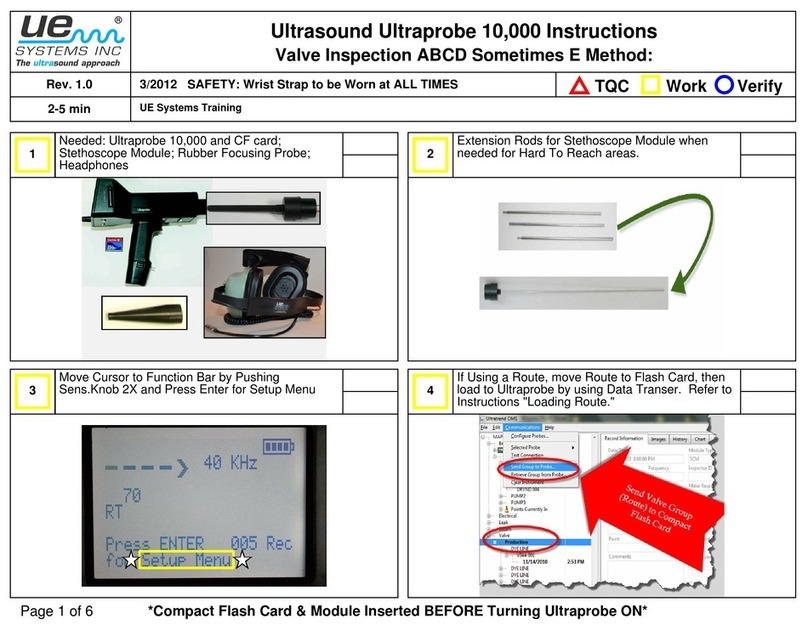
UE Systems
UE Systems ULTRAPROBE 10000 instructions

Craftsman
Craftsman 161.210400 owner's manual

Bosch
Bosch PHANTOM EDGE quick start guide

Bushnell
Bushnell Pro 1m 205107 instruction manual


