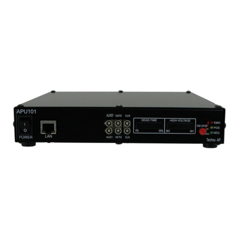
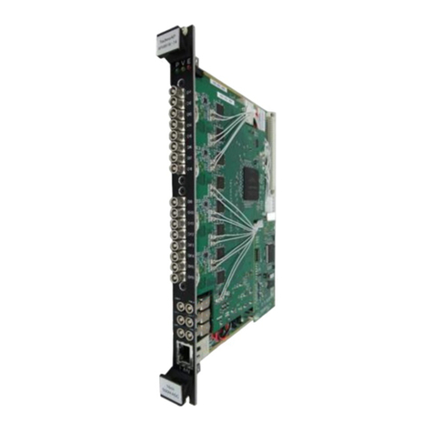
TechnoAP APV8M44 User manual

Hybrid Digital Spectrum Analyzer
APV8M44
APV8M24
Instruction Manual
Version1.2.4
2022, December
TechnoAPCo., Ltd.
Add:2976-15 Mawatari, Hitachinaka-shi,Ibaraki,Postcode:312-0012
TEL: +81-29-350-8011
FAX: +81-29-352-9013
URL: http://www.techno-ap.com
e-mail: info@techno-ap.com

APV8M44, APV8M24 Instruction Manual
2
TechnoAP Co., Ltd.
Safety Precautions / Disclaimer
ThankyouverymuchforpurchasingthedigitizerAPV8108-14 (hereinafter"Thisboard")ofTechnoAPCo.,
Ltd.(hereinafter"We").Pleasereadthis"SafetyPrecautions/Disclaimer"beforeusingthis device,besureto
observethecontents,anduseitcorrectly.
Wearenotresponsibleforanydamagecausedbyabnormalityofdevice,detector,connecteddevice,
application,damage tofailure,othersecondarydamage,evenifaccident caused byusing this device.
Prohibited matter
⚫This device cannot be used for applications requiring special quality and reliability
related to human life, accident.
⚫This device cannot be used in places with high temperature, high humidity and high
vibration.
⚫Do not apply a power supply that exceeds the rating.
⚫Do not turn the power on while other metals are in contact with the board surface.
Note
⚫If there is smoking or abnormal heat generation in this device, turn off the power
immediately.
⚫This board may not work properly in noisy environments.
⚫Be careful with static electricity.
⚫The specifications of this board and the contents of the related documents are subject
to change without notice.
Warrantypolicy
Thewarrantyconditionsof"ourproduct"areasfollows.
Warrantyperiod
Oneyearfrom dateofpurchase.
Guaranteecontents
Repairorreplacementwillbecarriedoutin case ofbreakdowneventhoughyou
haveusedcorrectlyaccordingtothisinstructionmanualwithinthewarrantyperiod
Outofwarranty
Wedonotwarrantyifthecauseofthefailurefallsunderanyofthefollowing.
1. Failure or damage due to misuse or improper repair or modification or
disassembly.
2.Failureanddamageduetofallingetc.
3.Breakdown/damageinharshenvironments(hightemperature/highhumidity,
underzero,condensationetc.).
4.Causesotherthantheabove,otherthan"ourproducts".
5.Consumables.

APV8M44, APV8M24 Instruction Manual
3
TechnoAP Co., Ltd.
- Contents -
Safety Precautions / Disclaimer...............................................................................................................................................................................2
1. Overview.....................................................................................................................................................................................................................5
2. Specifications........................................................................................................................................................................................................7
2.1. Specifications of DPP, from CH1 to CH4..............................................................................................................7
2.2. Specifications of DSP, from CH5 toCH8...............................................................................................................7
2.3. Common specifications................................................................................................................................................................8
3. Appearance............................................................................................................................................................................................................9
4. Setup.........................................................................................................................................................................................................................12
4.1. Installation of application.......................................................................................................................................................12
4.2. Connection.............................................................................................................................................................................................12
4.3. Set up of the network..............................................................................................................................................................13
5. Screen of the application.................................................................................................................................................................. 14
5.1. Startup screen...................................................................................................................................................................................14
5.2. Config tab................................................................................................................................................................................................17
5.3. file tab...........................................................................................................................................................................................................30
5.4. status tab.................................................................................................................................................................................................32
5.5. wave tab...................................................................................................................................................................................................33
5.6. spectrum tab....................................................................................................................................................................................... 34
5.7. timespectrum tab...........................................................................................................................................................................36
5.8. PSD tab *option...............................................................................................................................................................................37
6. DPP initialization............................................................................................................................................................................................38
6.1. Connection.............................................................................................................................................................................................38
6.2. Power ON................................................................................................................................................................................................ 38
6.3. Waveform Measurement......................................................................................................................................................38
6.4. Energy Spectrum Measurement..................................................................................................................................40
6.5. List and Time Difference Spectral Measurements.................................................................................41
6.6. Coincidence and anti-coincidence outputs....................................................................................................42
7. DSP initialization............................................................................................................................................................................................43
7.1. Connection.............................................................................................................................................................................................43
7.2. Power ON................................................................................................................................................................................................ 43
7.3. Confirmation of preamplifier output signal......................................................................................................43
7.4. Analog fine gain and analog pole zero adjustment of preamplifier output signal
45
7.5. FAST filter setting..........................................................................................................................................................................47
7.6. SLOW filters setting......................................................................................................................................................................49
7.7. Setting the SLOW threshold.............................................................................................................................................52
8. Measurement...................................................................................................................................................................................................53
8.1. Setting..........................................................................................................................................................................................................53

APV8M44, APV8M24 Instruction Manual
4
TechnoAP Co., Ltd.
8.2. Start measurement...................................................................................................................................................................... 53
8.3. Histogram mode.............................................................................................................................................................................. 53
8.4. List mode.................................................................................................................................................................................................. 54
8.5. Stop measurement...................................................................................................................................................................... 54
9. Quit............................................................................................................................................................................................................................... 54
10. File........................................................................................................................................................................................................................... 55
10.1. Histogram data file..................................................................................................................................................................55
10.2. Waveform data file.................................................................................................................................................................58
10.3. List data file...................................................................................................................................................................................... 59
10.4. List-Wave data file *Option.......................................................................................................................................... 61
10.5. PSD data file *Option..........................................................................................................................................................63
11. Troubleshooting.....................................................................................................................................................................................64
11.1. Connection error occurs................................................................................................................................................. 64
11.2. Command error occurs....................................................................................................................................................64
11.3. Histogram is not displayed.............................................................................................................................................65
11.4. Change IP address.................................................................................................................................................................65
12. Performance of APV8M44、8M24............................................................................................................................. 66
12.1. Resolution of DSP...................................................................................................................................................................66

APV8M44, APV8M24 Instruction Manual
5
TechnoAP Co., Ltd.
1. Overview
TechnoAP'sDigitalSpectrumAnalyzerAPV8M44andAPV8M24arehybriddigitalsignalprocessorswith
real-timeDPP(DigitalPulseProcessing)functionandDSP(DigitalSignal Processor)functionwithhigh-
speedandhigh-resolutionADC.
Figure1 Blockdiagram
TheAPV8M44isequippedwithDPPfromCH1toCH4,andinadditiontoreal-timesignalanalysisusinga
500MHzhigh-speedA/Dconverter,itperformshigh-speedprocessingwithnodeadtimebypipelinesignal
processingtoachievehightimeresolutionandhighthroughput.
TheAPV8M24isequippedwithDPPinCH1andCH2,andinadditiontoreal-timesignalanalysisusinga
1GHzhigh-speedA/Dconverter,itperformshigh-speedprocessingwithoutdeadtimebypipelinesignal
processingtoachievehightimeresolutionandhighthroughput.
TheAPV8M44andAPV8M24areequippedwithaDSPfromCH5toCH8,whichusesa62.5MHz,14Bit
A/Dconverter,andtheoutputsignalfromthedetectorpreamplifierisprocessedinreal-timebyatrapezoidal
filter(TrapezoidalFilter)processinginreal-timebyapipelinedFPGAarchitecture.Theconfiguration
integratesaspectroscopyamplifierandMCA,andperformspulseshapingusingthelatestdigitalsignal
processingtechniquesinsteadoftraditionalanalogmethods
Inadditiontotrapezoidalfilter,ithasfunctionssuchastimingfilteramplifier,CFD,waveformdigitizer,etc.
Thestandardconfigurationincludescoincidenceandanti-coincidenceterminals,allowingahighdegreeof
freedom insettingssuchascoincidencetimeandCHcombinations.
Thisdocumentdescribesanapplicationformeasurementandcontrolofourdigitalspectrum analyzer
products(hereafterreferredtoas"theApplication")
CFD
QDC
PSA
TDC Time
Energy
Rise, Fall, Total
DPP
DSP
TFA FAST
CFD
Trapezoidal
filter BLR PEAK
HOLD Energy
Time
DET Anode
DET Preamp
FPGA
DSP
DPP
1Gbps
Ethernet

APV8M44, APV8M24 Instruction Manual
6
TechnoAP Co., Ltd.
* Inthetext,"CH"is usedforthesignalinputchannel and"ch"forthenumber of bins andiscase-sensitive.
* Inthetext,"list"and"event"havethe samemeaning.
* The APV in the model’s name indicatestheVMEstandardsizeboardtype.AseparateVMEpowersupply
rack(suchasourAPV9007)isrequiredtosupplypowertothisboardtype.Inaddition,thetypeofmodelin
whichthisboardishousedinaunit(chassis)andACpowersupplycanbeuseddirectlyismarkedwithAPU
insteadofAPV.Asanexample,themodelinwhichtheVME-typeAPV8M44isinstalledinaunitis
APU8M44.(ThismanualalsoincludesdescriptionsoftheAPU8M44andAPU8M24.
* Additionalfunctionscanbeaddedtothisdeviceasoptions.(Inthisdocument,thefunctionpartisspecified
as(optional).

APV8M44, APV8M24 Instruction Manual
7
TechnoAP Co., Ltd.
2. Specifications
2.1. Specifications of DPP, from CH1 to CH4
(1) Analog Input
・Numberofchannel 2CH,APV8M44
4CH,APV8M24
・Inputrange ±1V
・Inputimpedance 50Ω
・Coarsegain ×1、×3
(2) ADC
・Samplingfrequency 500MHz,APV8M44
1GHz,APV8M24
・Resolution 14bit
・SNR 68.3dBFS@605MHz
(3) Performance
・QDC output 2Mcpsandmore
・Timeresolution 7.8125ps@500MHz, 3.90625ps@1GHz
(4) MCA
・ADCgain 4096、2048、1024、512、256 channel
2.2. Specifications of DSP, from CH5 toCH8
(1) Analog Input
・Numberofchannel 4CH
・Inputrange ±2V
・Inputimpedance 1kΩ
・Coarsegain ×1、×4、×10、×20
・Frequencyband DC to25MHz
(2) ADC
・Samplingfrequency 62.5MHz
・Resolution 16bit
・SNR 85dB@3MHz
(3) Performance
・Resolution 1.70keV@1.33MeV,typical value
・Spectrumbroadening 12 %orless,1Kcpsto 100Kcps
・Integralnon-linearity ±0.025%,typicalvalue
・Pulsepareresolution 1.25×(Risetime+ Flattoptime)
(4) MCA
・ADCgain 16384、8192、4096、2048、1024、512、256channel

APV8M44, APV8M24 Instruction Manual
8
TechnoAP Co., Ltd.
(5) Digitalpulseshaping
・Triggertiming LET(LeadingEdgeTiming)、
CFD(ConstantFractionDiscriminatorTiming)
・Timeresolution 62.5ps
2.3. Common specifications
(1) Communicationinterface
・LAN Ethernet TCP/IP 1000Base-TandUDP
(2) Form
・VMEtype APV8M44、APV8M24
・Desktoptype APU8M44、APU8M44
(3) Currentconsumption
*CaseofAPV8M44
+5V 4.0AMax.
+12V 1.0AMax
-12V 0.5AMax.
(4) Externaldimensions
・VMEtype 20 (W)x262 (H)x 187 (D) mm
・Desktoptype 300 (W) ×56 (H)x335(D)mm
(5) Weight
・VMEtype About460 g
・Desktop type About3360 g
(6) Computerenvironment
・OS VersionWindows7andmore、32bitor64bitandmore
・Network interface
・Screenresolution FHD (1920 x 1080)recommended

APV8M44, APV8M24 Instruction Manual
9
TechnoAP Co., Ltd.
3. Appearance
Photo1 APV8M24
(1) LED P (green) lights up when power is turned ON, V (orange) and E (red) are
not used
(2) CH1~4 LEMO00.250connectorforanode outputsignalinput.Inputrange±1V,coursegain
selectablefromapp. x1 or x3, input impedance 50Ω. CH1 and CH2 for APV8M24.
(3) CH5~8 LEMO00.250connectorforpreampoutputsignalinput.Inputrange±2V,x1,x4,x10,
x20 course gain selected from application, input impedance 1kΩ.
(4) MONI LEMO00.250connectorformonitoroutput; DAC output ofsignals,etc.during DSP
processingforCH5-8.
(5) COIN LEMO00.250connectorforcoincidenceoutput. Whena coincidenceis detected on
any CH,theLVTTLsignalisoutput foran arbitrarytime width.
(6) ACOIN LEMO 00.250connectorforanti-coincidenceoutput.Whenananti-coincidenceis
detectedonanyCH,theLVTTLsignalisoutputforan arbitrarytimewidth.
(7) CLK-I LEMO00.250connector forexternalclock signal input. Anexternalclockcanbeused
tosynchronizewithanexternaldevice.
Whenusinganexternalclock,see"*Whenusingan externalclock"below.
(8) CLK-O LEMO00.250connectorforexternalclocksignaloutput;outputs 25MHzLVTTL
signal.
(9) GATE LEMO00.250connectorforexternalGATEsignalinput,TTLorLVTTLsignalinput.
Dataacquisitionisenabledwhiletheinputis"High".
(10) VETO LEMO00.250connectorforexternalVETOsignalinput,TTL orLVTTLsignalinput.
Disablesdataacquisitionwhile"High".
(1)
(2)
(3)
(5)
(6)
(7)
(9)
(8)
(10)
(12)
(13)
(4)
(11)

APV8M44, APV8M24 Instruction Manual
10
TechnoAP Co., Ltd.
(11) CLR LEMO00.250connectorforexternalCLEARsignalinput;TTLorLVTTLsignalcan
beinputto GATEorVETO toapplycoincidencetotheentireboard.Clearsthetime
counterdataontherisingedgeof"High".
(12) AUX LEMO 00.250connector for optionaloutput;LVTTLORlogic (High if even1ofall
CHsisdetected)isoutput.
(13) LAN RJ45connectorforEthernetcable.EthernetTCP/IP1000Base-T.
Photo2 APV8M24, AllCHs,noattenuator,analogpole zeroadjustable through differential circuit.
(14) Jumperforattenuator Yellowframein thephotoabove.Whentheupper jumper is presentand
thelowerjumperisnotpresent,noattenuatorisset(default).Whentheupperjumper
isnotpresentandthelowerjumperis present,theattenuatorissetto1/10.
(15) First-stagedifferentialcircuitjumper Light blue frame in the photo above. Without the jumper, the
signal goes through the first-stage differential circuit to shorten the decay internally
(default).Whenajumperisattached,thesignalisdirectlyconvertedtoanalog-to-digital
(AD)withoutpassingthroughthedifferentialcircuit.
(16) Analogpole zerojumper Orangeframe inthe photoabove.When thejumperis present,the
analogpolezerocircuitisadjustableandisusedforresistivefeedbackpreamplifier
outputsignalinput, etc. (default).Without jumper, theanalog polezerocircuit is not
usedandcannotbeadjusted. Usedfortransistorresetpreamplifieroutputsignalinput,
etc.
(17) Evacuationjumper Purpleframeinthephoto above.Forevacuationwhentheabovejumper is
removed.
(3)
(14)
(15)
(16)
(17)

APV8M44, APV8M24 Instruction Manual
11
TechnoAP Co., Ltd.
*Whenexternalclockisused
Withthepoweroff,changethejumperJP21ontheboardto1-6:CPU,inputa25MHz,50%dutycycle
LVTTLorTTLsignaltoCLK-I,andthenturnthepoweron.
Photo3 Position ofJP21
Photo4Whenusinginternalclock(3-4:INTjumper)
Photo5 Whenusingexternalclock(1-6:CPUjumper)

APV8M44, APV8M24 Instruction Manual
12
TechnoAP Co., Ltd.
4. Setup
4.1. Installation ofapplication
This application runs on Windows.When using thisapplication,it is necessary to install the EXE (executable
format) file of this application and the LabVIEW runtime engine from National Instruments on the PC to be
used.
Installation of this application is performed by the installer included on the accompanying CD. The installer
includestheEXE(executableformat)fileandtheLabVIEWruntimeengine,whichcanbeinstalledatthesame
time.Theinstallation procedureisasfollows.
(1) Log in to Windowswithadministrative privileges.
(2) Runsetup.exeintheInstallerfolderonthesuppliedCD-ROM.Proceedwiththeinstallationinan
interactivemanner.ThedefaultinstallationdestinationisC:¥TechnoAP(3)Inthisfolder,the
executablefileofthisapplicationandtheconfigurationfileconfig.ini,inwhichthesettingvaluesare
saved,willbeinstalled.
(3) Startbutton-TechnoAP- RunAPP8M24.
Touninstall,gotoAddorRemoveProgramsandselectAPP8M24toremoveit.
4.2. Connection
ConnectthisdevicetoaPC withanEthernetcable;useacrossovercabledependingonthePC.When
usingahub,useaswitchinghub.

APV8M44, APV8M24 Instruction Manual
13
TechnoAP Co., Ltd.
4.3. Set up of the network
Checkthecommunicationstatusofthisdeviceandthisapplicationbythefollowingprocedure.
(1) Turn on the PC and change the network information of the PC.
IP address :192.168.10.2 *Addressesnotassignedtothisdevice
Sub-netmask :255.255.255.0
Defaultgateway :192.168.10.1
(2) Turn on the VME Crate power supply and wait for about 10 seconds after turning on the power.
(3) Check the communication status between the PC and the device by executing the ping command
at the Windows command prompt to see if the device and the PC are connected. The IP address of
the device is located on the board or on the back of the unit. The factory default network information
for this device is as follows.
IP address :192.168.10.128
Sub-net mask :255.255.255.0
Default gateway :192.168.10.1
> ping 192.168.10.128
Figure2 Confirmcommunicationconnection,executepingcommand
Launch this application. Search for APP8M24 from the shortcut icon APP8M24 on the desktop or the
Windows button and launch it.
(If an error message is displayed when this application is launched, stating that connection with this
device has failed, please refer to the troubleshooting described below.

APV8M44, APV8M24 Instruction Manual
14
TechnoAP Co., Ltd.
5. Screen of the application
5.1. Startup screen
Whenthisapplicationisrun,thefollowingstartupscreenwillappear.
Figure3 Startupscreen(maydifferfromimageduetooptionsandupdates)
Menu
File-openconfig Loadconfigurationfile
File-openhistogram Loadhistogram datafile
File-openwave Loadwaveformdatafile*option
File-openPSD LoadPSDdatafile*option
File-saveconfig Savecurrentsettingstoafile
File-savehistogram Savecurrenthistogramdatatofile
File-savewave Savewaveformdatafile*option
File-savePSD SavePSDdatafile*option
File-saveimage SavethisapplicationscreenasPNGformatimage
File-convertbinarylistfiletocsv OpenscreentoconvertlistdatafiletoCSVformat
File-quit Quitapplication
Edit-
copy setting of CH1
CH1andCH5settingsinCHtabarereflectedinotherCHsettings
Edit-
copy setting of CH1 to all module
CH1 and CH5 settings in the CH tab are reflected in the settings of
all otherboard

APV8M44, APV8M24 Instruction Manual
15
TechnoAP Co., Ltd.
Edit-IPconfigurationChangetheIPaddressofthisdevice
calibration Executewhenthereisadisturbanceinthe wavefrom CH1toCH4.
Config Setall items to thisdevice
Clear Initializehistogramdatainthisdevice
Start Startmeasurementtothisdevice
Stop Stopmeasurementtothisdevice
device Selectthedevicetobemeasured。
IPaddress IPAddress.IP addressdefinedintheconfigurationfileand selectedin Module
memo Youcanwrite notes.
mode Thefollowing modes canbeselected.
hist Histogrammodestoresthewaveheightvaluesofthepreamplifieroutput
signalinupto4096channelsforCH1toCH4,andupto16384channels
for CH5to CH8, andcreatesa histogram.
wave Youcancheckwaveformsduringsignalprocessinglikeanoscilloscope.
list List mode is a mode in which the time stamp, wave height value, and
CHnumberofthepreamplifieroutputsignalareusedasoneeventdata,
andthedataiscontinuouslytransferredtothePC.
measurementtime Setsthemeasurementtime.
listreadbyte(byte) Specifies the unit byte for reading listdata. Note that if the value is too small, the
readoutwillnotbecomplete,and anerrorwill occur whenoutputting highcounts.
acq.LED Flashingduringmeasurement
errorLED Errorindication
mode Displaysthecurrently selectedmode
measurementtime Displaysthesetmeasurementtime
measurementmode Measurementmode,displayingrealtimeorlivetime
realtime Real time (actualmeasurement time) ofthe effectivefirst CH.Equal
tothemeasurementtimeattheendofmeasurement.
livetime Live time (valid measurement time) of the first valid CH. real time -
deadtime.
filesize(Byte) Displaysthecapacity(in Bytes)ofthefileinwhichthelistdataisbeingsaved.
Tab
config CHsettingsandmeasurementsettings
file File-related settings.
status DisplaysthestatusofeachCH.
wave Displayofinputwaveforms,trapezoidalprocessedwaveforms,etc.
spectrum Displayofspectrum inhistmode.
timespectrum Whentimespectrum on/offischeckedinlistmode,timespectrumiscreatedfrom
the list data and displayed. Note that if you try to create a time spectrum at high
counts,thePCprocessingwillnotbeabletokeepupandanerrorwilloccurindata

APV8M44, APV8M24 Instruction Manual
16
TechnoAP Co., Ltd.
acquisition.

APV8M44, APV8M24 Instruction Manual
17
TechnoAP Co., Ltd.
5.2. Config tab
5.2.1. CH tab
DPP andDSP commonsettings
Figure4 configtab
ON enable CHAvailability.
polarity Thepolarityoftheinputsignal.posispositive polarity,negisnegativepolarity.
LLD (digit) Energy LLD (Lower Level Discriminator). Unit is digits (ch). Set to a value greater
thantheshowtriggerthresholdandlessthantheULD.
ULD (digit) EnergyULD(UpperLevelDiscriminator).Unitisdigits(ch).Chabovethisthreshold
isnotcounted;settoavaluegreaterthanLLD.
DACmonitortype DAC output waveform selection. the DAC output signal can be viewed on an
oscilloscopetochecktheinternalprocessingstatus.
preamp Differentiatedsignalfromthepreamplifieroutputsignal.
fast FASTfiltersignal.
slow SLOWfiltersignal.
CFD CFD signal
CHtab SettingsrelatedtoDPP'sCH
analogcoarse gain Analog coarsegain;selectfrom1xor3x.
baselinerestorerfilter Sets the time constant for the Baseline Restorer; choose from Ext (Excluded, no
AutoBLR), Fast, 4μs, 85μs, 129μs, or 260μs. Normally set to 85μs.
threshold(digit) Sets the threshold for waveform acquisition of the input signal. The unit is digits.
The setting range is from 0 to 8191. set it to a value greater than the noise level
whileviewingtherawwaveform inwavemode.

APV8M44, APV8M24 Instruction Manual
18
TechnoAP Co., Ltd.
ConstantfractiontimingofAPV8M44andAPV8M24is realizedbydigital signalprocessingusingFPGA.
The digital signal processing algorithm we have developed uses a polynomial approximation based on the
least-squaresmethodfromsampledwaveformdata.
Thetimeinformationiscalculatedmore preciselybyfindingthe parameters a, b, andcthatminimizethe time
information (i.e., the time information of the time of the data) and obtaining interpolation of the zero crossing
point(WALK)forCFDandthethresholdpointforleadingedge.
Furthermore, by using FPGAs to perform pipelined calculations, a series of calculations is performed very
quickly,withacalculationtimeoflessthan100ns,resultinginlowdeadtimeandhighthroughput.
Delay
MUX
×
ADD
+
f
S(n)
f(n)
CFDwaveform
Timepickoff
×
×

APV8M44, APV8M24 Instruction Manual
19
TechnoAP Co., Ltd.
g
h
CFD
timingtype Select the waveform to be used when time stamping the event detected (time
stamp)fromCFDwaveformorLE (rawwaveform).
CFD:ConstantFractionDiscriminatorTiming
For the different preamp waveforms, a and b in the figure below, the following
waveforms c,dande,fandg,h aregenerated.
Waveformsc,d:WaveformsaandbmultipliedbyCFDfunctionandinverted
Waveformse,f:WaveformsaandbdelayedbyCFDdelay
Waveformsg,h:Waveformscandepluswaveformsdandf
CFD,the zero-crossing timing of waveforms g and h, is characterized by the fact
that itis constanteven if thewave height changes, aslong asthe start time ofthe
riseofthewaveform isthesame.
Inputsignal
InvertsinputsignalmultipliedbyCFDfunction
InputsignaldelayedbyCFDDelay
Addreversalsanddelays
c
V1*CFD function
CFD delay
b
a
d
e
f
V1
V2
V2*CFD function

APV8M44, APV8M24 Instruction Manual
20
TechnoAP Co., Ltd.
Figure5 Thinking of ConstantFractionDisicriminatorTiming
LE LeadingEdge
This is the timing when a certain trigger level t is reached. (Trigger
acquisition timing is different if the slope of the rise is different, as in the
caseof'a'and'b',andthe timeisalso different.
Figure6 Thinkingof LeadingEdge
CFD function Magnification to reduce the original waveform forCFD waveform shaping. 0.03x,
0.06x,0.09x,and
(multiple) Select from 0.12x, 0.15x, 0.18x, 0.21x, 0.25x, 0.28x, 0.31x, 0.34x, 0.37x, 0.40x,
0.43x,0.46
生波形
x0.06
x0.46
CFD delay SelecttheCFDdelaytimefrom1nsto24ns.
生波形
2ns
24ns
CFD walk (digit) Set the threshold value for timestamping.The unit is indigits, and thevalue isset
nearthe0crossingpositionwhilewatchingtheCFDwaveforminwavemode.
WALK
Time Stamp
b
a
b’
a’
t
Rawwaveform
Rawwaveform
This manual suits for next models
1
Table of contents
Other TechnoAP Measuring Instrument manuals
Popular Measuring Instrument manuals by other brands

horiba
horiba S48 BM Series instruction manual
Guralp Systems
Guralp Systems 40T Operator's guide
Bosch
Bosch D-tect 150 Operating/safety instructions
Crosby
Crosby SP Handheld Plus SW-HHP user manual
AFLOWT
AFLOWT MT Pro M Series Operation manual

PCB Piezotronics
PCB Piezotronics IMI SENSORS ICP 628F01/ICS-43 Installation and operating manual
