Technogel Mantegel 20 Parts list manual

I
IN
NS
ST
TR
RU
UC
CT
TI
IO
ON
NS
S
F
FO
OR
R
I
IN
NS
ST
TA
AL
LL
LA
AT
TI
IO
ON
N,
,
U
US
SE
E
A
AN
ND
D
M
MA
AI
IN
NT
TE
EN
NA
AN
NC
CE
E
E
ED
D.
.
0
01
1-
-0
08
8
G
GB
B
M
MA
AN
NT
TE
EG
GE
EL
L
2
20
0
-
-
3
30
0
-
-
5
50
0
–
–
7
70
0
Condenser “ Water”
Condenser “ Air”
Condenser “ Air/Water”
Dispositive “ Granita”

C:\Documents and Settings\mconti.TECHNOGEL-USA\My Documents\MACCHINE\ARTESAN\ART
MANUALS\Mantegel\Inglese\MG 2V Istruzioni Inglese 01-08.doc
2
EDITION 01-08 –This manual is the exclusive property of TECHNOGEL spa.
Any unauthorized reproduction of part or whole of this document is prohibited

C:\Documents and Settings\mconti.TECHNOGEL-USA\My Documents\MACCHINE\ARTESAN\ART
MANUALS\Mantegel\Inglese\MG 2V Istruzioni Inglese 01-08.doc
3
Introduction
Thank you for choosing our product. For best results, we recommend that you read this instruction
manual carefully.
The descriptions and illustrations contained in this manual are not binding. TECHNOGEL reserves the
right to modify and improve, without notice and at any point, machine parts where deemed necessary
for construction and/or commercial motives.
Persons qualified to carry out the work depending on the type of work involved
Please note the symbols given at the side of each operation described for installation, use and
maintenance:
= Technician = User
Where the symbol of the Technician is indicated (an electrician, plumber or mechanic) this means that
the operations described can be carried out exclusively by these people. If the user attemps to carry
out these operations this could prove dangerous and he/she must refrain from doing so.
Installation and first start-up
The installation and first startup of this machine must be carried out by a TECHNOGEL
technician or one with TECHNOGEL authorization.
TECHNOGEL spa DECLINES ALL LIABILITY FOR INSTALLATIONS OR
STARTUPS CARRIED OUT BY UNAUTHORIZED PERSONS.

C:\Documents and Settings\mconti.TECHNOGEL-USA\My Documents\MACCHINE\ARTESAN\ART
MANUALS\Mantegel\Inglese\MG 2V Istruzioni Inglese 01-08.doc
4
How to unpack the machine
GROSS WEIGHT A B C
MANTEGEL 20 = KG. 280 mm. 730 1030 1730
MANTEGEL 30 = KG. 310 mm. 730 1030 1730
MANTEGEL 50 = KG. 355 mm. 730 1100 1730
MANTEGEL 70 = KG. 525 mm. 730 1320 1730
ATTENTION : DUE TO ITS NARROW AND HIGH SHAPE, THE MACHINE
MAY BE UNSTABLE DURING HOISTING.
Remove all the side and top wooden panels
Lift the machine using a fork lift truck, inserting the forks between the
machine base and the crate base
Under the crate base unscrew the four bolts that hold the machine
tightly in position
ATTENTION:
After removing these bolts, the base of the crate will drop to the
ground.
After removing the crate base, lower the fork lift truck and place the
machine on the ground.
The machine can now be moved by means of the handles.
THE TYPE OF WOOD USED FOR THE PACKING CRATE IS NATURAL SPRUCE,
NOT CHEMICALLY TREATED SO THAT IT CAN BE PERFECTLY RECYCLED.

C:\Documents and Settings\mconti.TECHNOGEL-USA\My Documents\MACCHINE\ARTESAN\ART
MANUALS\Mantegel\Inglese\MG 2V Istruzioni Inglese 01-08.doc
5
Hoisting the machine
NET WEIGHT A B C
MANTEGEL 20 = KG. 190 mm.490 620 1305
MANTEGEL 30 = KG. 220 mm.490 600 1330
MANTEGEL 50 = KG. 260 mm.490 740 1330
MANTEGEL 70 = KG. 435 mm.490 940 1400
ATTENTION: DUE TO ITS NARROW AND HIGH SHAPE, THE MACHINE
MAY BE UNSTABLE DURING HOISTING.
Lift the machine using a fork lift truck, inserting the forks from the side,
between the front and rear wheels.
Hoist the machine with belts near the front and rear wheels (as in
drawing).
The tie rod lifting the machine must be at the exact centre of the
machine.
Move the machine by holding the flange handle in one hand and the
corner of the machine in the other.
After positioning the machine, use your feet to lock with the front wheel
brakes.
NEVER USE YOUR HANDS

C:\Documents and Settings\mconti.TECHNOGEL-USA\My Documents\MACCHINE\ARTESAN\ART
MANUALS\Mantegel\Inglese\MG 2V Istruzioni Inglese 01-08.doc
6
Machine identification
Every machine is given a plate bearing:
machine type
electrical power
serial number
gas type and quantity
voltage and hertz ratings
This plate is found at the back of the machine. Below is the serial plate for this machine.
When ordering spare parts and requesting technical assistance, always quote the information given on
the serial plate:
MACHINE TYPE
MANTEGEL
SERIAL NUMBER
VOLTAGE
VOLT HZ

C:\Documents and Settings\mconti.TECHNOGEL-USA\My Documents\MACCHINE\ARTESAN\ART
MANUALS\Mantegel\Inglese\MG 2V Istruzioni Inglese 01-08.doc
7
P
PO
OS
SI
IT
TI
IO
ON
NE
EM
ME
EN
NT
T
M
MA
AC
CH
HI
IN
NE
E
C
CO
ON
ND
DE
EN
NS
SE
ER
R
F
FO
OR
R
W
WA
AT
TE
ER
R
C
CO
ON
NN
NE
EC
CT
TI
IO
ON
N
W
WA
AT
TE
ER
R
E
EN
ND
D
E
EL
LE
EC
CT
TR
RI
IC
CA
AL
L
technician qualificate:
ELECTRICIAN PLUMBER

C:\Documents and Settings\mconti.TECHNOGEL-USA\My Documents\MACCHINE\ARTESAN\ART
MANUALS\Mantegel\Inglese\MG 2V Istruzioni Inglese 01-08.doc
8
Dimensions and different facilities: MANTEGEL 20
Dimensions and weight:
A–width
B–depth
C
H–height
Weight
19” 3/8
490 mm.
24” 7/16
620 mm.
7” 7/8
200 mm.
51” 3/8
1305 mm.
419 Lb.
190 Kg.
WARNING:
For the good functioning, the machine does not have to be anchored to the floor, neither some
particular technical precaution are to be taken to limit the vibration transmission.
The installation requires the following operations:
Around the machine perimeter, leave an operat ive space of at least 10” (25 cm) necessary to carry
out the works smoothly.
Make sure the machine is steady by blocking the brakes (F) of the front wheels using the feet (DO
NOT USE THE HANDS).
Connect the hidro-system with the water inlet and outlet (see above picture point W). For the
pressure and consumption data refer to page 12 (MANTEGEL 20).
Connect the electric system (see above picture point E). For the power and absorption data refer to
page 10 (Table A - MANTEGEL 20).

C:\Documents and Settings\mconti.TECHNOGEL-USA\My Documents\MACCHINE\ARTESAN\ART
MANUALS\Mantegel\Inglese\MG 2V Istruzioni Inglese 01-08.doc
9
Dimensions and different facilities: MANTEGEL 30
Dimensions and weight:
A–width
B–depth
C
H–height
Weight
19” 3/8
490 mm.
24” 7/16
620 mm.
7” 7/8
200 mm.
52” 3/8
1330 mm.
485 Lb.
220 Kg.
WARNING:
For the good functioning, the machine does not have to be anchored to the floor, neither some
particular technical precaution are to be taken to limit the vibration transmission.
The installation requires the following operations:
Around the machine perimeter, leave an operative space of at least 10” (25 cm) necessary t o carry
out the works smoothly.
Make sure the machine is steady by blocking the brakes (F) of the front wheels using the feet (DO
NOT USE THE HANDS).
Connect the hidro-system with the water inlet and outlet (see above picture point W). For the
pressure and consumption data refer to page 12(MANTEGEL 30). Connect, also, the washing
water (L) cold or hot according to the availability.
Connect the electric system (see above picture point E). For the power and absorption data refer to
page 10 (Table A - MANTEGEL 30).

C:\Documents and Settings\mconti.TECHNOGEL-USA\My Documents\MACCHINE\ARTESAN\ART
MANUALS\Mantegel\Inglese\MG 2V Istruzioni Inglese 01-08.doc
10
Dimensions and different facilities: MANTEGEL 50
Dimensions and weight:
A–width
B–depth
C
H–height
Weight
19” 3/8
490 mm.
29” 1/2
750 mm.
7” 7/8
200 mm.
52” 3/8
1330 mm.
640 Lb.
290 Kg.
WARNING:
For the good functioning, the machine does not have to be anchored to the floor, neither some
particular technical precaution are to be taken to limit the vibration transmission.
The installation requires the following operations:
Around the machine perimeter, leave an operat ive space of at least 10” (25 cm) necessary to carry
out the works smoothly.
Make sure the machine is steady by blocking the brakes (F) of the front wheels using the feet (DO
NOT USE THE HANDS).
Connect the hidro-system with the water inlet and outlet (see above picture point W). For the
pressure and consumption data refer to page 12 (MANTEGEL 50). Connect, also, the washing
water (L) cold or hot according to the availability.
Connect the electric system (see above picture point E). For the power and absorption data refer to
page 10 (Table A - MANTEGEL 50).

C:\Documents and Settings\mconti.TECHNOGEL-USA\My Documents\MACCHINE\ARTESAN\ART
MANUALS\Mantegel\Inglese\MG 2V Istruzioni Inglese 01-08.doc
11
Dimensions and different facilities: MANTEGEL 70
Dimensions and weight:
A–width
B–depth
C
H–height
Weight
19” 3/8
490 mm.
37”
940 mm.
7” 7/8
200 mm.
55”
1400 mm.
960 Lb.
435 Kg.
WARNING:
For the good functioning, the machine does not have to be anchored to the floor, neither some
particular technical precaution are to be taken to limit the vibration transmission.
The installation requires the following operations:
Around the machine perimeter, leave an operat ive space of at least 10” (25 cm) necessary to carry
out the works smoothly.
Make sure the machine is steady by blocking the brakes (F) of the front wheels using the feet (DO
NOT USE THE HANDS).
Connect the hidro-system with the water inlet and outlet (see above picture point W). For the
pressure and consumption data refer to page 12 (MANTEGEL 70). Connect, also, the washing
water (L) cold or hot according to the availability.
Connect the electric system (see above picture point E). For the power and absorption data refer to
page 10 (Table A - MANTEGEL 70).
C:\Documents and Settings\mconti.TECHNOGEL-USA\My Documents\MACCHINE\ARTESAN\ART
MANUALS\Mantegel\Inglese\MG 2V Istruzioni Inglese 01-08.doc
12
Electrics installation
The electrical installation, which the machine is connected to, must be carried out by a skilled
electrician according to regulations and observing the Laws in force. An efficient electrical
installation with earthing is the most important thing in order for your machine to work
perfectly.
Fit a suitable wall switch: we strongly recommend fitting an automatic differential switch. See table
(A) for power rating and absorption details.
Check taht the mains voltage rate is the same as the machine rating, shown on the serial number plate
(see page 5).
The power cable has 4 wires: the yellow/green wire is the earth wire, the other three are for the three
phases.
Table (A):
MANTEGEL 20
V.220
50HZ
V.220
60HZ
V.200
50/60HZ
V.380
50HZ
V.380
60HZ
V.415
50HZ
Total power KW
2,6
2,6
4
2,6
2,6
2,6
Max. absorp. A.
10,5
10,5
19
6,5
7,5
6,5
Power cable
Wires & section
4 x 2,5
mm²
4 x 2,5
mm²
4 x 4
mm²
4 x 1,5
mm²
4 x 2,5
mm²
4 x 1,5
mm²
MANTEGEL 30
V.220
50HZ
V.220
60HZ
V.200
50/60HZ
V.380
50HZ
V.380
60HZ
V.415
50HZ
Total power KW
4,2
4,2
4,2
4,2
4,2
Max. absorp. A.
11,2
11,2
19,5
7
8
6,5
Power cable
Wires & section
4 x 4
mm²
4 x 4
mm²
4 x 4
mm²
4 x 2,5
mm²
4 x 2,5
mm²
4 x 2,5
mm²
MANTEGEL 50
V.220
50HZ
V.220
60HZ
V.200
50/60HZ
V.380
50HZ
V.380
60HZ
V.415
50HZ
Total power KW
6
6
6
6
Max. absorp. A.
20
20
13
12
Power cable
Wires & section
4 x 6
mm²
4 x 6
mm²
4 x 4
mm²
4 x 4
mm²
MANTEGEL 70
V.220
50HZ
V.220
60HZ
V.200
50/60HZ
V.380
50HZ
V.380
60HZ
V.415
50HZ
Total power KW
11,2
11,2
11,2
11,2
11,2
Max. absorp. A.
36
36
45
21
20
Power cable
Wires & section
4 x 10
mm²
4 x 10
mm²
4 x 10
mm²
4 x 6
mm²
4 x 6
mm²
TECHNOGEL CANNOT BE HELD LIABLE FOR ANY DAMAGE ARISING FROM
INCORRECT INSTALLATION OR MAINS DEFECTS.

C:\Documents and Settings\mconti.TECHNOGEL-USA\My Documents\MACCHINE\ARTESAN\ART
MANUALS\Mantegel\Inglese\MG 2V Istruzioni Inglese 01-08.doc
13
Water connection
The refrigeration system has a water-cooled condenser. A connection for the hot or cold water pipe
exists. It is useful for washing the machine. Its tap and nozzle are in the front of the machine.
Connect the mains hose to the fitting that reads " ENTRATA ACQUA- WATER INLET ".
The drain hose must be connected to the fitting that reads " USCITA ACQUA-WATER OUTLET ".
The connection plates and fittings are inside the machine: to access these, remove the rear panel.
To connect the machine to the mains, we recommend using a rubber hose suitable for up to 10 bars
with an inside diameter of about 15 mm (matching the fittings supplied with the machine).
If, for any reason, the plates indicating water inlet and outlet are illegible, please note that the water
inlet hose is fitted to the pressure-switch valve.
WATER PRESSURE AND CONSUMPTION
If the machine is using mains water, check that the incoming water has a pressure of at least 1 bar.
If the water pressure is more than 5 bar, fit a pressure reducer to the system, to reduce this to 4 bar.
Average water consumption (when the refrigerating unit is on) is:
- MANTEGEL 20 = 80/100 litres/hours*
- MANTEGEL 30 = 100/190 litres/hour*
- MANTEGEL 50 = 150/250 litres/hours*
- MANTEGEL 70 = 300/450 litres/hours*
* depending on the temperature of the incoming water.
If the water contains impurities, fit a purifying filter to avoid scaling and/or damage to the
pressure-switch valve.

C:\Documents and Settings\mconti.TECHNOGEL-USA\My Documents\MACCHINE\ARTESAN\ART
MANUALS\Mantegel\Inglese\MG 2V Istruzioni Inglese 01-08.doc
14

C:\Documents and Settings\mconti.TECHNOGEL-USA\My Documents\MACCHINE\ARTESAN\ART
MANUALS\Mantegel\Inglese\MG 2V Istruzioni Inglese 01-08.doc
15
M
MA
AC
CH
HI
IN
NE
E
P
PO
OS
SI
IT
TI
IO
ON
NI
IN
NG
G
C
CO
ON
ND
DE
EN
NS
SE
ER
R
F
FO
OR
R
A
AI
IR
R
O
O
A
AI
IR
R
/
/
W
WA
AT
TE
ER
R
C
CO
ON
NN
NE
EC
CT
TI
IO
ON
NS
S
Technician qualificate:
ELECTRICIAN PLUMBER
IF The machine works with isolate condenser,you’ ll have to contact the:
REFRIGERATOR TECHNICIAN

C:\Documents and Settings\mconti.TECHNOGEL-USA\My Documents\MACCHINE\ARTESAN\ART
MANUALS\Mantegel\Inglese\MG 2V Istruzioni Inglese 01-08.doc
16
TECHNOGEL spa CANNOT BE HELD RESPONSIBLE FOR ANY DAMAGE CAUSED BY
INCORRECT POSITIONING OF THE MACHINE IN AN UNSUITABLE PLACE. THE
COMPANY IS ALSO UNABLE TO ASSUME ANY RESPONSIBILITY FOR INADEQUATE
PERFORMANCE OF THE MACHINE OWING TO OPERATING CONDITIONS BEING
BEYOND THE LIMITS OF ACCEPTABILITY.
Positioning of machine with fixed air condenser
VALID FOR MACHINES WITH EITHER AIR CONDENSATION OR AIR/WATER COMBINED
It is extremely important that the machine should be installed in a spacious room with doors
and windows so the air heated by the machine can be changed regularly.
The rear of the machine must be place at a distance of at least 0.5 metres from the wall.
During operation of the machine, the doors and windows in the room must be left open
otherwise the air heated by the machine will become extremely hot and could reach
temperatures of around 50°C. If the machine is allowed to operate in these conditions the
main components (refrigerator compressor and turbine motor) could well overheat over the
long term and this could jeopardize correct operation of the machine and cause damage which
would be costly to repair. It would also mean an increase in running costs owing to the high
consumption of electricity w hile the machine’ s performance w ould be reduced by 50% .
IDEAL POSITIONING OF THE MACHINE
As shown in the diagram, the air coming in through the door (1) is sucked in and heated
during condensation of the ventilators (2) and is pushed in the direction of the window (3)
and thus outside.
The ideal solution, though not always easy to put into practice, is to make holes in the wall
(4) opposite the ventilators (2). The air can therefore flow out freely without any problem and
the machine’ s performance w ill alw ays be excellent.

C:\Documents and Settings\mconti.TECHNOGEL-USA\My Documents\MACCHINE\ARTESAN\ART
MANUALS\Mantegel\Inglese\MG 2V Istruzioni Inglese 01-08.doc
17
Positioning of the machine with remote air condenser
In order to combat problems of overheating of the air, whenever possible the remote air condenser
should be mounted.
CAUTION:
Copper or flexible piping (T) transporting the refrigerant gas from the machine to the condenser and
vice versa,
Should not exceed 4 metres in length.
The condenser must be fixed to wall brackets positioned high up so that they are beyond the reach of
people of average height.
As illustrated in the diagram, the condenser must be positioned at least 200 mm from the wall so that
air can be sucked in without any problem. It is also advisable to install protective roofing over the
equipment to protect it from rain water.
with remote air condenser
The machine must be installed by a Refrigeration Technician who after connecting the equipment will
check that the quantity of gas inside the machine is correct for optimum operation.

C:\Documents and Settings\mconti.TECHNOGEL-USA\My Documents\MACCHINE\ARTESAN\ART
MANUALS\Mantegel\Inglese\MG 2V Istruzioni Inglese 01-08.doc
18
Cooling Machine fixed
Dimension / Weigh MANTEGEL 20 Air
A- Width
B–Depth
C–Console Table
H–Height
Weight
490 mm
1120 mm
200 mm.
1305
220 Kg.
Dimension / Weigh MANTEGEL 30 Air
490 mm
1120 mm
200 mm.
1305
250 Kg.
Dimension / Weigh MANTEGEL 50 Air
490 mm
1300 mm
200 mm.
1305
290 Kg.
WARNINGS:
After positioning the machine and locking the front wheels by pressing on the brake with the feet (do
not use the hands for this operation), check that the feet (P) both rest on the floor. If the feet (P) are
not level, during operation the condenser could move around owing to movement of the ventilators.
If the machine operates in contact with other machines, make sure there is a space of at least 25
cm between them.
Carry out the electrical connections of the machine and make sure that the electric cable (E) comes
from above and is not laid on the floor where it could be crushed. For data on power and
absorption please see page 22 Table A under the specific machine reference.
For the MANTEGEL 30 and MANTEGEL 50 machines, it is possible to connect hot or cold water
for washing purposes to the rear of the machine.

C:\Documents and Settings\mconti.TECHNOGEL-USA\My Documents\MACCHINE\ARTESAN\ART
MANUALS\Mantegel\Inglese\MG 2V Istruzioni Inglese 01-08.doc
19
Cooling Machine Arranged air water
Dimension / Weigh MANTEGEL 20 Air / Water
A- Width
B–Depth
C–Console Table
H–Height
Weight
490 mm
1120 mm
200 mm.
1305
230 Kg.
Dimension / Weigh MANTEGEL 30 Air / Water
490 mm
1120 mm
200 mm.
1305
260 Kg.
Dimension / Weigh MANTEGEL 50 Air / Water
490 mm
1300 mm
200 mm.
1305
300 Kg.
FIXED COOLING AIR / WATER MACHINE
WARNINGS:
After positioning the machine and locking the front wheels by pressing on the brake with the feet (do
not use the hands for this operation), check that the feet (P) both rest on the floor. If the feet (P) are
not level, during operation the condenser could move around owing to movement of the ventilators.
If the machine operates in contact with other machines, make sure there is a space of at least 25
cm between them.
Carry out the electrical connections of the machine and make sure that the electric cable (E) comes
from above and is not laid on the floor where it could be crushed. For data on power and
absorption please see page 22 Table A under the specific machine reference.
Connect the water supply (W) to the machine with inlet and outlet for the condensation from the
refrigerating unit. For instructions on how to connect the machine, please see pages 8, 9 or 10
depending on the type of machine. For data on pressure and consumption, please see page 15.
(Page 19 only).
For the MANTEGEL 30 and MANTEGEL 50 machines, it is possible to connect hot or cold water
for washing purposes to the rear of the machine.

C:\Documents and Settings\mconti.TECHNOGEL-USA\My Documents\MACCHINE\ARTESAN\ART
MANUALS\Mantegel\Inglese\MG 2V Istruzioni Inglese 01-08.doc
20
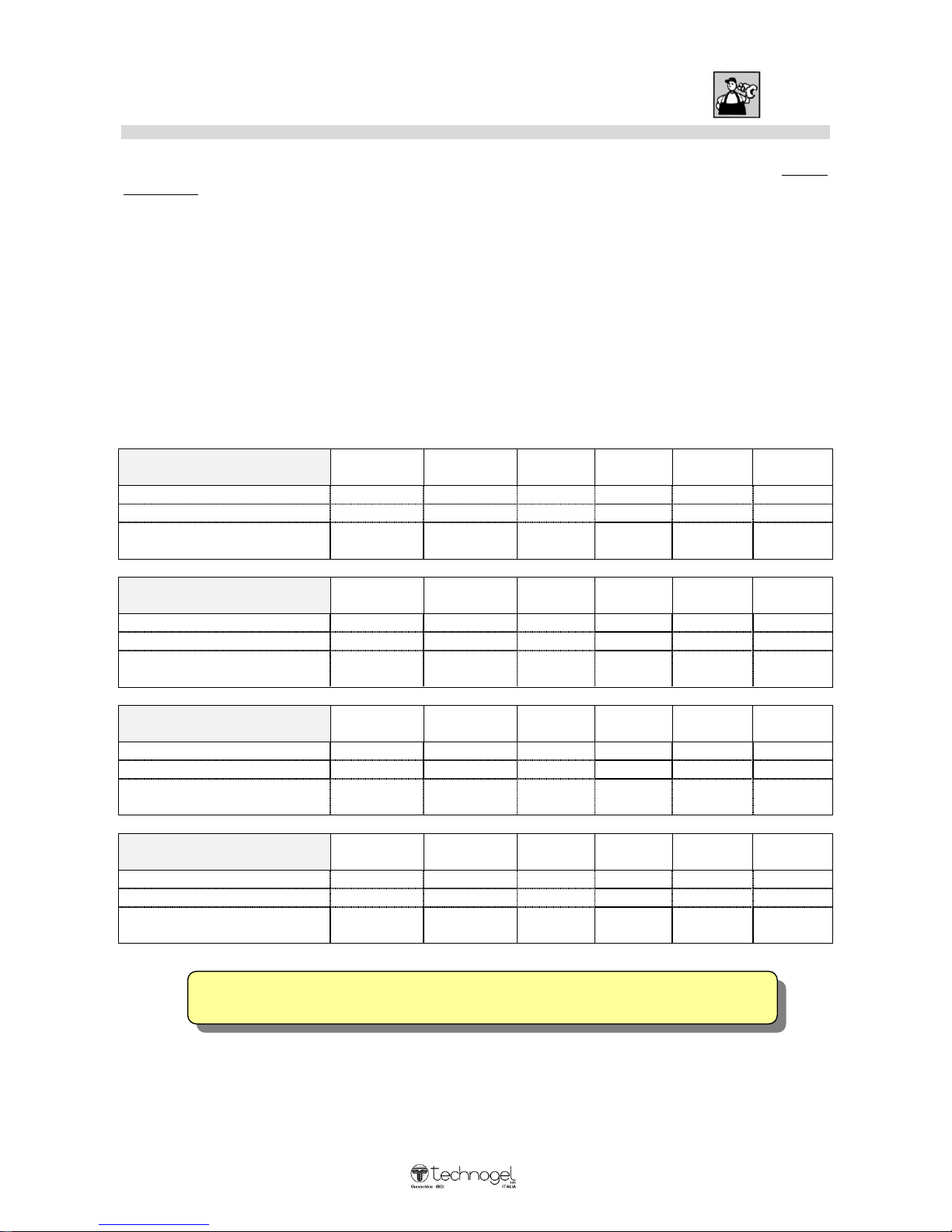
TECHNOGEL spa CANNOT ASSUME ANY RESPONSIBILITY FOR ACCIDENTS
CAUSED BY IMPROPER INSTALLATION OR FAULTY WIRING
Electric installation
COOLING MACHINE AIR O AIR / WATER
The electrical installation, which the machine is connected to, must be carried out by a skilled
electrician in compliance with regulations and the Laws in force. An efficient electrical
installation with earthing is most important to ensure your machine works perfectly.
Fit a suitable wall switch: we strongly recommend fitting an automatic differential switch. See table
(A) for power rating and absorption details.
Check that the mains voltage is the same as the machine rating, shown on the serial number plate
(see page 6).
When the cable has 4wires, the yellow/green wire is the earth and the other three are the three
phases.
When the cable has 5wires, the yellow/green wire is the earth - the blue wire is neutral - the other
three are the three phases.
- TABLE -A-
MANTEGEL 20 Air
V.220
50 HZ
V.220
60 HZ
V.400
50 HZ
V.380
60 HZ
Total power KW.
3
3
3
Absorbtion edge A.
12
12
8
Wire line
Branch screw
4 x 2,5mm²
4 x 2,5mm²
4 x 1,5mm²
MANTEGEL 30 Air
V.220
50 HZ
V.220
60 HZ
V.400
50 HZ
V.380
60 HZ
Total power KW.
3,2
3,2
3,2
Absorbtion edge A.
13
13
8,5
Wire line
Branch screw
4 x 4mm²
4 x 4mm²
4 x 2,5mm²
MANTEGEL 50 Air
V.220
50 HZ
V.220
60 HZ
V.400
50 HZ
V.380
60 HZ
Total power KW.
5,2
5,2
5,2
Absorbtion edge A.
21
21
14,5
Wire line
Branch screw
4 x 6mm²
4 x 6mm²
4 x 4mm²
This manual suits for next models
3
Table of contents
Other Technogel Ice Cream Maker manuals


Popular Ice Cream Maker manuals by other brands

Ninja
Ninja CREAMI quick start guide

Taylor
Taylor Freezemaster 336 Original operating instructions

Vollrath
Vollrath Stoelting CC101A Operator's manual

Kambrook
Kambrook Little Chefs Soft Scoops KLCIA4 Instruction booklet

Cuisinart
Cuisinart ICE31U manual

Vollrath
Vollrath Stoelting CBB Series Operator's manual


