Vollrath Stoelting CBB Series User manual

Model CBB
OPERATORS MANUAL
Manual No. 513851 Rev.0


This manual provides basic information about the machine. Instructions and suggestions are
given covering its operation and care.
The illustrations and specifications are not binding in detail. We reserve the right to make
changes to the machine without notice, and without incurring any obligation to modify or pro-
vide new parts for machines built prior to date of change.
DO NOTATTEMPT to operate the machine until instructions and safety precautions in this
manual are read completely and are thoroughly understood. If problems develop or questions
arise in connection with installation, operation, or servicing of the machine, contact Stoelting.
Stoelting Foodservice Equipment
502 Highway 67
Kiel, WI 53042-1600
U.S.A.
Main Tel: 800.558.5807
Fax: 920.894.7029
Customer Service: 888.429.5920
Fax: 800.545.0662
© 2014 PW Stoelting, LLC
stoeltingfoodservice.com

Safety Alert Symbol:
This symbol Indicates danger, warning or caution.
Attention is required in order to avoid serious per-
sonal injury. The message that follows the symbol
contains important information about safety.
Signal Word:
Signal words are distinctive words used throughout
this manual that alert the reader to the existence and
relative degree of a hazard.
CAUTION
The signal word “CAUTION” indicates a potentially
hazardous situation, which, if not avoided, may result
in minor or moderate injury and equipment/property
damage.
A Few Words About Safety
Safety Information
Read and understand the entire manual before
operating or maintaining Stoelting equipment.
This manual provides the operator with information
for the safe operation and maintenance of Stoelting
equipment. As with any machine, there are hazards
associated with their operation. For this reason safety
is emphasized throughout the manual. To highlight
specific safety information, the following safety defini-
tions are provided to assist the reader.
The purpose of safety symbols is to attract your at-
tention to possible dangers. The safety symbols, and
their explanations, deserve your careful attention
and understanding. The safety warnings do not by
themselves eliminate any danger. The instructions
or warnings they give are not substitutes for proper
accident prevention measures.
If you need to replace a part, use genuine Stoelting
parts with the correct part number or an equivalent
part. We strongly recommend that you do not use
replacement parts of inferior quality.
WARNING
The signal word “WARNING” indicates a potentially
hazardous situation, which, if not avoided, may result
in death or serious injury and equipment/property
damage.
CAUTION
The signal word “CAUTION” not preceded by the
safety alert symbol indicates a potentially hazardous
situation, which, if not avoided, may result in equip-
ment/property damage.
NOTE (or NOTICE)
The signal word “NOTICE” indicates information or
procedures that relate directly or indirectly to the
safety of personnel or equipment/property.

Section Description Page
1 Description and Specifications
1.1 Description..................................................................................................1
1.2 Specifications .............................................................................................2
2 Installation Instructions
2.1 Safety Precautions .....................................................................................3
2.2 Shipment and Transit..................................................................................3
2.3 Machine Installation....................................................................................3
2.4 Setting the Control......................................................................................3
3 Initial Set-Up and Operation
3.1 Operator’s Safety Precautions....................................................................5
3.2 Operating Controls and Indicators..............................................................5
3.3 Assembly of Machine .................................................................................6
3.4 Sanitizing....................................................................................................7
3.5 Freeze Down and Operation ......................................................................7
3.6 Removing Mix From Machine.....................................................................8
3.7 Disassembly of Machine Parts...................................................................8
3.8 Cleaning and Sanitizing the Machine Parts................................................8
3.9 Routine Cleaning........................................................................................9
3.10 Preventative Maintenance..........................................................................9
4 Settings & Alarms
4.1 Making Adjustments ...................................................................................11
4.2 Settings.......................................................................................................11
4.3 Alarms ........................................................................................................12
4.4 Pressure Switch..........................................................................................12
5 Replacement Parts
5.1 Tank and Cover ..........................................................................................13
5.2 Handle Assembly and Auger Parts.............................................................14
TABLE OF
CONTENTS


Owner’s Manual #513851 1 CBB Model Machines
SECTION 1
DESCRIPTION AND SPECIFICATIONS
1.1 DESCRIPTION
The CBB counter machines are equipped with fully au-
tomatic controls to provide a uniform product. They will
operate with almost any type of commercial soft serve or
non-dairy mixes available, including: ice milk, ice cream,
yogurt, and frozen dietary desserts.
This manual is designed to help qualified service per-
sonnel and operators with the installation, operation and
maintenance of the CBB machines.
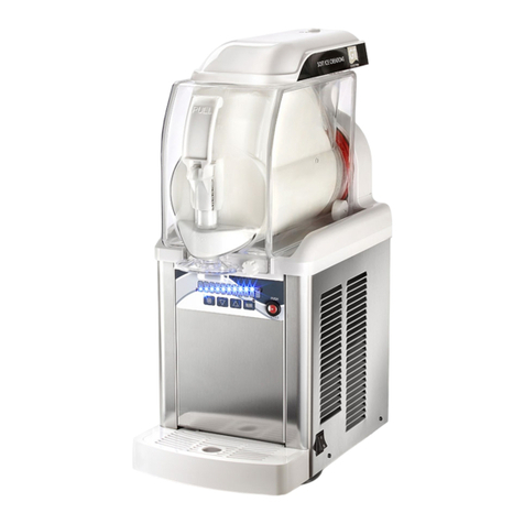
Figure 1-1 Model CBB116-37

Owner’s Manual #513851 2 CBB Model Machines
1.2 SPECIFICATIONS
Model CBB116
Dimensions Machine
width 11’’ (27,9 cm)
height 28’’ (71,1 cm)
depth 19’’ (48,3 cm)
Weight 65 lbs (29,4 kg)
Electrical 1 Phase, 115 VAC, 60Hz
running amps 10A
connection type NEMA5-15P power cord provided
Compressor 850 Btu/hr
Drive Motor 0.134 hp
Air Flow Air cooled units require 10” air space on both sides and back
Tank Volume 1 gallon

Owner’s Manual #513851 3 CBB Model Machines
SECTION 2
INSTALLATION INSTRUCTIONS
2.1 SAFETY PRECAUTIONS
Do not attempt to operate the machine until the safety
precautionsandoperatinginstructionsinthismanualare
read completely and are thoroughly understood.
Take notice of all warning labels on the machine. The la-
bels have been put there to help maintain a safe working
environment.Thelabelshavebeendesignedtowithstand
washing and cleaning. All labels must remain legible for
thelifeofthemachine.Labelsshouldbecheckedperiodi-
callytobesuretheycanberecognizedaswarninglabels.
If danger, warning or caution labels are needed, indicate
thepartnumber,typeoflabel,locationoflabel,andquantity
required along with your address and mail to:
STOELTING
ATTENTION: Customer Service
502 Hwy. 67
Kiel, Wisconsin 53042
2.2 SHIPMENT AND TRANSIT
Themachinehasbeenassembled,operatedandinspected
at the factory. Upon arrival at the final destination, the
entire machine must be checked for any damage which
may have occurred during transit.
With the method of packaging used, the machine should
arriveinexcellentcondition.THECARRIERISRESPON-
SIBLE FOR ALL DAMAGE IN TRANSIT, WHETHER
VISIBLE OR CONCEALED. Do not pay the freight bill
until the machine has been checked for damage. Have
the carrier note any visible damage on the freight bill. If
concealeddamageand/or shortage isfoundlater, advise
the carrier within 10 days and request inspection. The
customermustplaceclaimfordamagesand/orshortages
in shipment with the carrier. Stoelting, Inc. cannot make
any claims against the carrier.
2.3 MACHINE INSTALLATION
Installation of the machine involves moving the machine
close to its permanent location, removing all crating, set-
ting in place, assembling parts, and cleaning.
A. Uncrate the machine.
B. Remove the packing material and move the
machine into place. Do not lift the machine by
thetank,augers,orhandles.Onlyliftbygrasping
the bottom of the machine.
C. Correctventilationisrequired.TheCBBmachine
requires 10” clearance on both sides and 12”
clearance at the back.
D. Install the drip tray.
E. Make sure the Main Power Switch is in the Off
position.
F. Connect the power cord to the proper power
supply. Check the nameplate on on front of the
machine for the required power supply. The
unit must be connected to a properly grounded
receptacle. The electrical cord furnished as part
of the machine has a three prong grounding
type plug. The use of an extension cord is not
recommended, if necessary use one with a size
12gaugeorheavierwithgroundwire.Donotuse
anadaptertogetaroundgroundingrequirement.
G. Clean and sanitize the machine before the first
use.
2.4 SETTING THE CONTROL
A. Turn onthemachineand press the Menubutton.
CAUTION
Do not install the machine outdoors. Exposure to
weather conditions or wet and damp locations can
damage the machine
WARNING
Do not alter or deform electrical plug in any way.
Alteringtheplugtofitintoan outlet of differentcon-
figuration may cause fire, risk of electrical shock,
product damage and will void warranty.
Cold
Selection
Auger
Movement
Menu
Arrow
Button
Figure 2-1 Control Board

Owner’s Manual #513851 4 CBB Model Machines
B. Press the up or down arrows to navigate to the
DateoptionandpresstheAugerMovementbutton
NOTE
The Auger Movement button acts as an “enter”
button in the menu screens.
C. Set the date. Use the Cold Selection button to
movethecursorandthearrowbuttonstochange
the value. The date format is DD/MM/YYYY.
D. Press the Auger Movement button to save the
value.
E. Press the down arrow to navigate to the Time
option and press the Auger Movement button.
F. Set the time using the Cold Selection button and
arrowbuttons.Thetimeisdisplayed in a24-hour
format.
G. Press the Auger Movement button to save the
value.
H. Press the down arrow button to navigate to the
NightModeoptionandpresstheAugerMovement
Button.
I. Set the On and Off settings as needed using the
arrow buttons and Cold Selection button.
NOTE
The On setting is the time when Night Mode be-
gins. The Off setting is when Night Mode ends.
The settings are displayed in a 24-hour format. If
the On and Off settings are the same, night mode
is deactivated.
J. Press the Auger Movement button to save the
value.
K. Press the down arrow button to navigate to the
TLIoptionandpresstheAugerMovementbutton.
L. Use the arrow buttons to change the setting to
-8.5.
M. Press the Auger Movement button to save the
value
N. PresstheMenubuttontoexitthesettingsscreens.

Owner’s Manual #513851 5 CBB Model Machines
SECTION 3
INITIAL SET-UP AND OPERATION
3.1 OPERATOR’S SAFETY PRECAUTIONS
SAFE OPERATION IS NO ACCIDENT; observe these
rules:
A. Know the machine. Read and understand the
Operating Instructions.
B. Notice all warning labels on the machine.
C. Wear proper shoes and clothing. Avoid loose
fitting garments, and remove watches, rings or
jewelry that could cause a serious accident. Do
not operate with wet hands or feet.
D. Do not allow children to use the machine.
E. Maintain a clean work area. Avoid accidents by
cleaning up the area and keeping it clean.
F. Stay alert at all times. Know which switch, push
button or control you are about to use and what
effect it is going to have.
G. Disconnectelectricalcordformaintenance.Never
attempt to repair or perform maintenance on the
machineuntilthemainelectricalpowerhasbeen
disconnected. Unplug the machine at the plug.
Do not pull the electrical cord to disconnect the
machine from the power source.
H. Donotoperateunderunsafeoperatingconditions.
Neveroperatethemachineifunusualorexcessive
noise or vibration occurs.
3.2 OPERATING CONTROLS AND INDICATORS
Before operating the machine, it is required that the op-
erator know the function of each operating control. Refer
to Figure 3-1 for the location of the operating controls on
the machine.
A. Main Power Switch
The Main Power Switch is used to control the
operation of the refrigeration system and the
augers. When the switch is in the Off position,
power will not be supplied to the control board,
refrigeration system or augers. Place it in the On
position for normal operation.
Figure 3-1 Controls
WARNING
High voltage will shock, burn or cause death. The
Main Power switch must be placed in the Off posi-
tionpriorto disassembling forcleaningorservicing.
Do not operate machine with the panels removed.
Main Power
Switch

Owner’s Manual #513851 6 CBB Model Machines
B. Control Board
Auger Movement
TheAugerMovementbuttoncontrolstheoperation
oftheaugers.Theaugersmustberotatingtostart
the refrigeration cycle.
Menu
The Menu button is used to access the machine
settings.
Cold Selection
The Cold Selection button will change the
refrigerationcycle.Pressthe<<>>buttontotoggle
betweensoftmode,sleepmodeandrefrigeration
off.
Arrow Buttons
TheArrow Buttons are used to navigate through
the menu screens. The buttons are also used
change settings within the menu.
3.3 ASSEMBLY OF MACHINE
All parts should be cleaned, sanitized and allowed to air
dry before assembling.
Toassemblethemachineparts,refertothefollowingsteps:
NOTE
Petrol-Gel sanitary lubricant or equivalent must be
usedwhenlubrication of machinepartsis specified.
NOTE
The United States Department of Agriculture and
theFoodand DrugAdministration requirethatlubri-
cants used on food processing equipment be certi-
fied for this use. Use lubricants only in accordance
with the manufacturer’s instructions.
A. Press the gear into bottom of the vertical auger
andlubricatethegearteethwithsanitarylubricant.
Installtheaugerandsecureittothemachinewith
the fastening nut.
B. Press the gear onto the back of the horizontal
auger. Lubricate the gear teeth and the front of
theaugerwithsanitarylubricant.Installtheauger.
C. Install the gasket onto the auger support and
install the support into the tank.
D. Place the gasket into the bottom groove on the
tank. Make sure the joint of the gasket is on one
of the two rear corners of the tank.
E. Install the tank onto the machine and secure it
with the tank clamps. Screw the tank fastening
knobs into the tank clamps.
F Install the rosette cap.
G. Install the o-ring onto the spigot assembly and
applyathinfilmofsanitarylubricanttotheo-ring.
H. Install the spigot assembly into the tank.
Cold
Selection
Auger
Movement
Menu
Arrow
Button
Figure 3-2 Control Board
Figure 3-3 Installing Augers
Vertical
Auger
Horizontal
Auger
Gear
Gear
Fastening
Nut
Auger
Support

Owner’s Manual #513851 7 CBB Model Machines
I. Install the spigot handle onto the tank knobs.
J. Secure the pivot arms to the spigot to the handle
knobs. NOTE
Assemble both pivot arms onto the handle knobs
at the same time to prevent the arms from twisting
and breaking.
3.4 SANITIZING
Sanitizingmustbedoneafterthemachine iscleanedand
justbeforethehopperisfilledwithmix.Sanitizingthenight
beforeisnoteffective.However,youshouldalwaysclean
the machine and parts after each use.
The United States Department of Agriculture and
the Food and Drug Administration require that all
cleaning and sanitizing solutions used with food
processing equipment be certified for this use.
Whensanitizingthe machine,referto localsanitaryregu-
lationsforapplicablecodesandrecommendedsanitizing
products and procedures. The frequency of sanitizing
must comply with local health regulations.
Mix sanitizer according to manufacturer’s instructions to
provide a 100 parts per million (ppm) strength solution
and check the solution with chlorine test strips. Allow
sanitizer to contact the surfaces to be sanitized for 5
minutes. Any sanitizer must be used only in accordance
with the manufacturer’s instructions.
In general, sanitizing may be conducted as follows:
A. Prepare Stera-Sheen Green Label Sanitizer
or equivalent according to manufacturer’s
instructionstoprovidea100ppmstrengthsolution.
Mix the sanitizer in quantities of no less than
2 gallons of 90° to 110°F (32° to 43°C) water.
Checkthestrengthofthesanitizingsolution.Use
a chlorine test strip and color chart to make sure
the solution has 100 ppm.Any sanitizer must be
usedonlyinaccordancewiththemanufacturer’s
instructions.
B. Pour the sanitizing solution into the tank.
C. PresstheMainPowerSwitchtoturnthemachine
on. Press the Auger Movement Switch to start
the auger. Make sure the display reads Motor
On. Check for leaks.
NOTE
Make sure the display reads Motor On. If it does
not, press the Cold Selection button until it does.
D. Clean sides of the tank, the vertical auger and
underside of tank cover using a clean soft bristle
brush dipped in the sanitizing solution.
E. After five minutes, place a container under the
spigot and open spigot to drain most sanitizing
solution. Leave a small amount of the sanitizing
solution in the freezing cylinder. Press theAuger
Movement button to stop the auger.
F. Collect the remaining sanitizing solution in a cup
andtestthechlorinecontentswithanewteststrip.
A reading of 100 ppm or more is acceptable.
If the reading is less than 100 ppm, sanitize the
machine again.
Ifthereadingislessthan100ppmaftersanitizing
the second time, disassemble and wash the
machine again.
3.5 FREEZE DOWN AND OPERATION
This section covers the recommended operating proce-
dures for the safe operation of the machine.
A. Sanitize just prior to use.
B. Pour 1 gallon of chilled mix into the tank.
C. Place the top cover onto the tank and lock the
cover.
D. Press the Auger Movement button and the Cold
Selection button. The display reads “Soft Mode
Please Wait.” NOTE
Press the Cold Selection button multiple times to
toggle between soft mode, sleep mode and motor
on (refrigeration off) mode.
Figure 3-4 Assembling Tank
Spigot
Handle
Knobs
Pivot
Arms

Owner’s Manual #513851 8 CBB Model Machines
E. Product will be ready to serve in 40-60 minutes.
The time it takes to be ready is dependent upon
many variables including the mix temperature
when poured into the tank, the amount of sugars
andbutterfatinthemixandthetemperaturesetting
on the machine.
F. Whenthedisplayreads“READYTOSERVE”the
product is ready, pull the spigot handle open to
serve.
3.6 REMOVING MIX FROM MACHINE
To remove the mix from the machine, refer to the follow-
ing steps:
A. Press the Cold Selection button until the display
shows Motor On.
B. Drain the mix by repeatedly opening and closing
the spigot. A container should be placed under
the spigot to collect the liquid mix.
D. Whenthemixisdrained,fillthetankwith1gallon
ofcooltapwater.After30secondsopenthespigot
to drain the water out of the machine.
C. UseStera-Sheenorequivalentsanitizingsolution
according to manufacturer’s instructions to
provide a 100 parts per million strength solution.
Any sanitizer must be used only in accordance
with the manufacturer’s instructions.
D. Pour the sanitizer into the tank.
E. After 5 minutes, drain the sanitizer out of the
freezing cylinder.
F. Press the Auger Movement button to stop the
auger. Press the Main Power Switch to turn the
machine off.
3.7 DISASSEMBLY OF MACHINE PARTS
Inspectionforworn orbrokenpartsshould be madeeach
time the machine is disassembled. All worn or broken
parts should be replaced to ensure safety to both the
operatorandthecustomerandtomaintaingoodmachine
performance and a quality product.
NOTE
The frequency of cleaning the machine and ma-
chine parts must comply with local health regula-
tions.
Afterthemix has beenremovedfrom the machine,follow
the steps below to disassemble the parts.
A. Remove the spigot by pulling the pivot arms
slightly outwards to disengage them from the
handle knobs.
NOTE
Pull both arms at the same time to prevent them
from twisting and breaking.
B. Remove the spigot handle by tilting it back and
pulling upwards.
C. Remove the rosette cap.
D. Remove the tank fastening knobs from the tank
clamps. Unclamp and remove the tank from the
machine. Remove the gasket from the bottom of
the tank. Remove the auger support and gasket
from the tank.
E. Pull the horizontal auger towards the front of the
machine to remove it. Remove the gear from the
back of the auger.
F. Unscrew the fastening nut from the top of the
vertical auger and remove the auger. Remove
the gear from the bottom of the auger.
G. Remove the o-ring from the spigot assembly.
Remove the o-ring by squeezing the it upward
with a dry cloth. When a loop is formed, roll the
o-ring out of the groove.
H. Remove condensate tray, drip tray and drip tray
grid.
3.8 CLEANING AND SANITIZING THE
MACHINE PARTS
Place all loose parts in a pan or container and take to
the wash sink for cleaning. Local and state health codes
dictatetheprocedurerequired.Somehealthcodesrequire
a four-sink process (pre-wash, wash, rinse, sanitize, and
air-dry), while other codes require a three-sink process
(without the pre-wash step). The following procedures
are a general guideline only. Consult your local and state
health codes for procedures required in your location.
A. Prepare Stera-Sheen or equivalent cleaner in
2 gallons of 90° to 110°F (32° to 43°C) water
following manufacturers instructions.
B. Prepare sanitizing solution according to
manufacturer’sinstructionstoprovidea100ppm
strength solution. Mix the sanitizer in quantities
of no less than 2 gallons of 90° to 110°F (32° to
43°C) water. Check the strength of the sanitizing
solution. Use a chlorine test strip and color chart
to make sure the solution has 100 ppm.
C. Place all parts in the cleaning solution and clean
the parts with brushes and sponges. Rinse all
partswith clean90°to110°F (32°to43°C)water.
Place the parts in the sanitizing solution.
D. Removethepartsfromthesanitizingsolutionand
allow them to air dry.

Owner’s Manual #513851 9 CBB Model Machines
E. Wash the steel tank bottom on the machine with
the 90° to 110°F (32° to 43°C) cleaning solution.
3.9 ROUTINE CLEANING
To remove spilled or dried mix from the machine exterior,
wash with warm soapy water and wipe dry. Do not use
highly abrasive materials.
3.10 PREVENTIVE MAINTENANCE
A. DAILY
1. Clean the drip tray.
2. The exterior should be kept clean at all times. A
mildalkalinecleanerisrecommended.Useasoft
cloth or sponge to apply the cleaner.
B. MONTHLY
Air Cooled Condenser Cleaning
A. Disconnect power to the machine.
B. Thefilterisattachedtotherearbytabsintherear
panel.Pressthetabsdownwardsandremovethe
filter.
C. Visually inspect the filter for dirt. If it is dirty,
shake or brush the excess dirt off the filter and
wash in a warm, soapy water. Once it is clean,
rinsethoroughly, shake dry andinstallitonto the
machine. NOTE
If the condenser is not kept clean, refrigeration ef-
ficiency will be lost.

Owner’s Manual #513851 10 CBB Model Machines

Owner’s Manual #513851 11 CBB Model Machines
SECTION 4
SETTINGS & ALARMS
ThecontrolontheCBBmachineallowsservicepersonnel
the ability to make adjustments to the machine through
the touchpad.
4.1 MAKING ADJUSTMENTS
A. Press the Menu button. The first adjustment
screen will be displayed (Keyboard).
B. Press the up or down arrow to scroll through
the adjustment screens and press the Auger
Movement button
NOTE
The Auger Movement button acts as an “enter”
button in the menu screens.
C. Press the Auger Movement button to go to the
setting screen.
D. Presstheupanddownarrowstochangethevalue
and press the Cold Selection button to move the
cursor.
E. Whenthe settingiscorrectlyprogrammed,press
the Auger Movement button to save the setting
and return to the menu screen.
F. Continue changing settings as needed.
G. PresstheMenubuttontoexitthesettingsscreens.
4.2 SETTINGS
KEYBOARD
The Keyboard can be locked to prevent
unauthorized use. When the Keyboard Lock
is active the current status screen will show a
triangle in the upper right corner of the display.
The touchpad will remain locked until the setting
is changed or the power is disconnected and
reconnected.
DATE
The Date setting is used to set the current date.
The date format is DD/MM/YYYY.
TIME
The Time setting is used to set to the local time.
It is a 24-hour clock.
NIGHT MODE
The Night Mode keeps the product around 28ºF.
The On setting is when Night Mode starts and
the Off setting is when it ends.
TLI
The TLI setting is the lower temperature limit
setting(in ºC).Whenthistemperatureisreached
the solenoid will close and stop refrigeration to
the evaporator. NOTE
If the menu button is held down for 10 seconds
while turning the machine on the display will show
temperature in Fahrenheit.
DOSE COUNTER
This displays the number of servings since the
counter was reset. The dose counter records
servings only when “READY TO SERVE” is on
the display. To reset the counter, press and hold
the Cold Selection button to until the display
shows “000”.
TANK TEMP
Thisdisplaysthe product temperature reading in
the tank.
SERVICE
The options under the Service are for use by a
qualifiedtechnicianandincludechangingthegear
motor RPMs, solenoid settings and serve ready
display time.
Figure 4-1 Controls
Cold
Selection
Auger
Movement
Menu
Arrow
Button

Owner’s Manual #513851 12 CBB Model Machines
4.3 ALARMS
Alarmsonthecontrolareshownbyaflashingboxsymbol
on the display. Determine if the auger is rotating when
the symbol is displayed.
AUGER ROTATING
When the auger rotating the alarm indicates
that the torque required to turn the auger is near
the cutoff. The cooling system will turn off for 2
minutes to attempt to thaw the product before it
automatically restarts.
AUGER NOT ROTATING
Whentheaugerisnotrotatingthealarmindicates
that the torque required to turn the auger has
reached the cutoff. The cooling system will turn
off for 10 minutes to attempt to thaw the product.
After 10 minutes it will automatically restart.
Make sure there is a maximum of 1 gallon of mix
in the tank.
4.4 PRESSURE SWITCH
AsolidlightnexttotheMainPowerswitchindicatesahigh
pressureconditionin the refrigeration system. Follow the
instructions below to reset the pressure switch:
A. Unplug the machine from the power source and
remove the filter located in the rear panel.
B. Checkif thecondenserfilterneedstobecleaned
(Section 3.10).
C. Make sure there is at least 10” airspace on both
sides and 12” airspace at the back.
D. Plug the machine in and press the pressure
switch button to reset it. The pressure switch is
located on the bottom of the machine below the
main power switch.
E. If the problem persists, contact a technician.

Owner’s Manual #513850 14 CBE Model Machines
5.2 HANDLE ASSEMBLY AND AUGER PARTS
Part Description Quantity
175558 Locking Screw - Tank Clamp 2
266185 Lever - Tank Clamp 2
266186 Hook - Tank Clamp 2
292378 Pivot Arm - Right (Spigot) 1
292379 Dowel - Pivot Arms (Spigot) 1
340004 Spigot 1
396766 Auger Support Bushing 1
396767 Gasket - Spigot Assembly 1
396768 O-Ring - Spigot Assembly 1
428105 Pivot Arm - Left (Spigot) 1
428106 Handle - Spigot 1
538620 Fastening Nut - Vertical Auger 1
556649 Base - Tank Clamp 2
674224 Auger - Vertical w/Bushing and Gear 1
674225 Shaft Sleeve - Transmission 1
674226 Auger - Horizontal 1
684027 Gasket - Auger Support Bushing 1
266186
266185
175558
556649
674226
428105
340004
674225
292378
674224
428106
538620
396768
292379
396767
684027
396766
This manual suits for next models
1
Table of contents
Other Vollrath Ice Cream Maker manuals

Vollrath
Vollrath Stoelting E131-OT2 User manual

Vollrath
Vollrath Stoelting U411 User manual

Vollrath
Vollrath STOELTING SF144 User manual

Vollrath
Vollrath STOELTING CC101W User manual

Vollrath
Vollrath Stoelting CC101A User manual

Vollrath
Vollrath Stoelting Flavor Burst STL-40BLD-JR User manual

Vollrath
Vollrath Stoelting Flavor Burst STL-80SS-DLX User manual

Vollrath
Vollrath Stoelting F212 User manual

Vollrath
Vollrath STOELTING Flavor Burst STL-40SS-JR User manual

Vollrath
Vollrath Stoelting CC303W User manual