manuals.online logo
Brands
  1. Home
  2. •
  3. Brands
  4. •
  5. Technosoft
  6. •
  7. Servo Drive
  8. •
  9. Technosoft Micro 4803 MZ Use and care manual

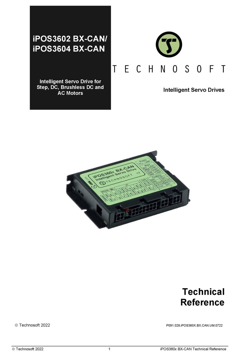
Technosoft Micro 4803 MZ Use and care manual

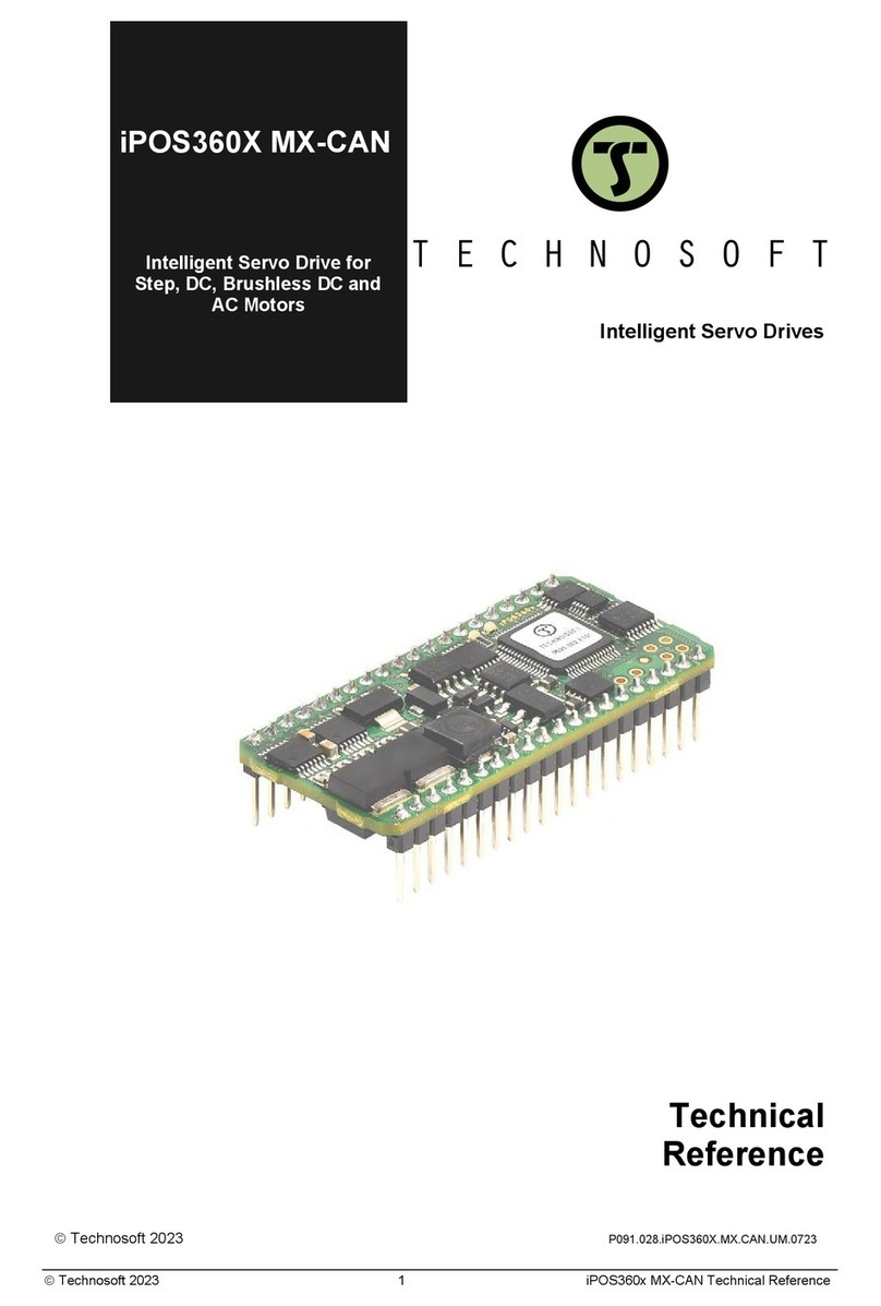
Micro 4803
MZ / PZ / CZ / HZ
Intelligent Servo Drive for DC,
Brushless DC and AC Motors
Intelligent Servo Drives
Technical
Reference
©Technosoft 2023 P091.020.Micro 4803 MZ.PZ.CZ.HZ.UM.0523A
©Technosoft 2023 2 Micro 4803 MZ / PZ / CZ / HZ Technical Reference
Table of contents
Table of contents ........................................................................................................... 2
Read This First ............................................................................................................... 5
About This Manual................................................................................................................. 5
Notational Conventions......................................................................................................... 5
Trademarks ............................................................................................................................ 6
Related Documentation ......................................................................................................... 6
If you Need Assistance … ..................................................................................................... 7
1Safety information.................................................................................................... 7
1.1 Warnings....................................................................................................................... 7
1.2 Cautions........................................................................................................................ 8
1.3 Quality system, conformance and certifications ....................................................... 8
2Product Overview..................................................................................................... 9
2.1 Introduction .................................................................................................................. 9
2.2 Product Features........................................................................................................ 10
2.3 Identification Labels................................................................................................... 11
2.4 Supported Motor-Sensor Configurations ................................................................. 13
2.4.1......Single loop configurations...................................................................................................... 13
2.4.2......Dual loop configurations ........................................................................................................ 13
3Hardware Installation............................................................................................. 14
3.1 Micro 4803 MZ Dimensions ...................................................................................... 14
3.2 Micro 4803 PZ Dimensions ....................................................................................... 14
3.3 Micro 4803 HZ Dimensions....................................................................................... 15
3.4 Micro 4803 CZ Dimensions....................................................................................... 15
3.5 Mechanical Mounting................................................................................................. 16
3.5.1......Recommended spacing for Micro 4803 MZ/PZ/HZ ............................................................... 16
3.5.2......PCB Design ........................................................................................................................... 17
3.5.2.1 Motherboard PCB Design............................................................................................... 18
3.5.2.2 Recommendations for the PCB Design.......................................................................... 18
3.5.2.3 EtherCAT signals PCB routing indications ..................................................................... 19
3.6 Connectors and Pinouts ............................................................................................ 23
3.6.1......Pinouts for Micro 4803 MZ/PZ ............................................................................................... 23
3.6.2......Pinouts for Micro 4803 HZ-CAN ............................................................................................ 24
3.6.3......Pinouts for Micro 4803 CZ ..................................................................................................... 25
3.6.4......Mating Connectors for Micro 4803 CZ................................................................................... 26
3.7 Connection diagrams................................................................................................. 27
3.7.1......Micro 4803 MZ/PZ-CAN connection diagram ........................................................................ 27
3.7.2......Micro 4803 MZ/PZ-CAT connection diagram ........................................................................ 27
3.7.3......Micro 4803 CZ-CAN connection diagram .............................................................................. 28
3.7.4......Micro 4803 CZ-CAT connection diagram .............................................................................. 28
©Technosoft 2023 3 Micro 4803 MZ / PZ / CZ / HZ Technical Reference
3.7.5......Micro 4803 HZ-CAN connection diagram .............................................................................. 29
3.8 Digital I/O Connection................................................................................................ 30
3.8.1......NPN inputs............................................................................................................................. 30
3.8.2......NPN outputs........................................................................................................................... 31
3.8.3......Solenoid driver connection for motor brake ........................................................................... 32
3.9 Analog Inputs Connection......................................................................................... 33
3.9.1.1 Recommendation for wiring............................................................................................ 33
3.10 Motor connections.................................................................................................. 34
3.10.1....Brushless Motor connection .................................................................................................. 34
3.10.2....DC Motor connection ............................................................................................................. 35
3.10.2.1 Recommendations for motor wiring................................................................................ 35
3.11 Feedback connections ........................................................................................... 36
3.11.1....Feedback #1 - Single-ended Incremental Encoder Connection ............................................ 36
3.11.2....Feedback #1 - Differential Incremental Encoder Connection ................................................ 37
3.11.3....Feedback #2 - Single-ended Incremental Encoder Connection ............................................ 38
3.11.4....Feedback #2 - Differential Incremental Encoder Connection ................................................ 39
3.11.5....Feedback #1 –Absolute Encoder Connection: SSI, BiSS, EnDAT....................................... 40
3.11.7....Feedback #2 –Absolute Encoder Connection: SSI, BiSS, EnDAT....................................... 42
3.11.9....Linear (Analog) Hall Connection............................................................................................ 44
3.11.10..Digital Hall Connection for Motor + Hall + Incremental or Absolute Encoder........................ 45
3.11.11..Digital Hall Connection for Motor + Digital Hall only control .................................................. 46
3.11.11.1 General recommendations for feedback wiring ............................................................. 47
3.12 Power Supply Connection...................................................................................... 48
3.12.1.1 Recommendations for Supply Wiring ............................................................................. 49
3.12.1.2 Recommendations to limit over-voltage during braking ................................................. 49
3.13 USB connection ...................................................................................................... 50
3.14 Serial RS-232 connection ....................................................................................... 51
3.14.1.1 Recommendation for wiring............................................................................................ 52
3.15 CAN-bus connection............................................................................................... 52
3.15.1.1 Recommendation for wiring............................................................................................ 53
3.16 EtherCAT Connection............................................................................................. 54
3.16.1....Recommendations for EtherCAT Wiring................................................................................ 54
3.16.2....EtherCAT signals schematic considerations ......................................................................... 55
3.17 Disabling Autorun (for CAN drives); Disabling the setup table (for CAT drives) 56
3.17.1....Disabling Autorun (for CAN drives)........................................................................................ 56
3.17.2....Disabling the setup table at startup (for CAT drives) ............................................................. 56
3.18 LED Indicators......................................................................................................... 57
3.18.1....EtherCAT® RUN and ERROR LED Indicators ...................................................................... 58
3.19 Axis ID Selection and Operation Mode.................................................................. 58
3.19.1....Axis ID Selection for Micro 4803 MZ/PZ-CAT ....................................................................... 58
3.19.2....Axis ID Selection and Operation Mode for Micro 4803 MZ/PZ-CAN..................................... 59
3.19.3....Axis ID Selection for Micro 4803 CZ-CAT ............................................................................. 60
3.19.4....Axis ID Selection and Operation Mode for Micro 4803 CZ-CAN ........................................... 60
4Electrical Specifications........................................................................................ 61
4.1 0BOperating Conditions................................................................................................. 61
4.2 1BStorage Conditions .................................................................................................... 61
4.3 2BMechanical Mounting................................................................................................. 61
©Technosoft 2023 4 Micro 4803 MZ / PZ / CZ / HZ Technical Reference
4.4 3BEnvironmental Characteristics.................................................................................. 61
4.5 4BLogic Supply Input (+VLOG) ........................................................................................ 62
4.6 Motor Supply Input (+VMOT) ..................................................................................... 62
4.7 6BMotor Outputs (A/A+, B/A-, C) ................................................................................... 62
4.8 7BDigital Inputs (IN0, IN1, IN2/LSP, IN3/LSN, IN4, IN5) ................................................ 63
4.9 7B RS-232........................................................................................................................ 63
4.10 USB .......................................................................................................................... 63
4.11 Digital Outputs (OUT0, OUT1, OUT4)..................................................................... 63
4.12 9BDigital Hall Inputs (Hall1, Hall2, Hall3) ................................................................... 63
4.13 11BEncoder Inputs (A1+, A1-, B1+, B1-, Z1+, Z1-, A2+, A2-, B2+, B2-) ...................... 64
4.14 13BAnalog Input (REF,FDBK)....................................................................................... 64
4.14.1....0…5V Mode ........................................................................................................................... 64
4.14.2....±10V Mode............................................................................................................................. 64
4.15 14BSSI/BiSS/Panasonic/ EnDAT/Nikon/Sanyo Denki encoder interface ................... 64
4.16 Supply Output (+5V) ............................................................................................... 65
4.17 CAN-Bus for CAN executions ................................................................................ 65
4.18 EtherCAT ports for CAT execution ........................................................................ 65
4.19 Conformity............................................................................................................... 65
5De-rating curves..................................................................................................... 66
6Memory Map ........................................................................................................... 67
©Technosoft 2023 5 Micro 4803 MZ / PZ / CZ / HZ Technical Reference
Read This First
Whilst Technosoft believes that the information and guidance given in this manual is correct, all parties must rely upon
their own skill and judgment when making use of it. Technosoft does not assume any liability to anyone for any loss or
damage caused by any error or omission in the work, whether such error or omission is the result of negligence or any
other cause. Any and all such liability is disclaimed. All rights reserved. No part or parts of this document may be
reproduced or transmitted in any form or by any means, electrical or mechanical including photocopying, recording or
by any information-retrieval system without permission in writing from Technosoft S.A. The information in this
document is subject to change without notice.
About This Manual
This book is a technical reference manual for:
Product Name
Part Number
Description
Nominal current
Peak Current
Communication
Micro 4803 MZ-CAT
P020.001.E122
Pins Version
3ARMS / 4.2A
10.6ARMS / 15A
RS232, USB, EtherCAT®
Micro 4803 MZ-CAN
P020.001.E102
RS232; USB; CAN
Micro 4803 PZ-CAT
P020.001.E322
Enhanced
Pins Version
4ARMS / 5.6A1
10.6ARMS / 15A
RS232, USB, EtherCAT®
Micro 4803 PZ-CAN
P020.001.E302
RS232; USB; CAN
Micro 4803 CZ-CAT
P020.801.E222
Standalone
Version
4ARMS / 5.6A
10.6ARMS / 15A
RS232, USB, EtherCAT®
Micro 4803 CZ-CAN
P020.801.E202
RS232; USB; CAN
Micro 4803 HZ-CAN
P020.001.E202
Connectors
Version
3ARMS / 4.2A
10.6ARMS / 15A
RS232; CAN
In order to operate the Micro 4803 drives, you need to pass through 3 steps:
❑Step 1 Hardware installation
❑Step 2 Drive setup using Technosoft EasySetUp software for drive commissioning
❑Step 3 Motion programming using one of the options:
❑CANopen master
2
or an EtherCAT® master
3
❑The drives built-in motion controller executing a Technosoft Motion Language (TML) program
developed using Technosoft EasyMotion Studio software
❑A TML_LIB motion library for PCs (Windows or Linux)
4
❑A TML_LIB motion library for PLCs1
❑A distributed control approach which combines the above options, like for example a host calling
motion functions programmed on the drives in TML
This manual covers Step 1 in detail. It describes the Micro 4803 hardware including the technical data, the
connectors and the wiring diagrams needed for installation.
For Step 2 and 3, please consult the document EasyMotion Studio –Quick Setup and Programming Guide. For
detailed information regarding the next steps, refer to the related documentation.
Notational Conventions
This document uses the following conventions:
•Micro 4803–all products described in this manual
•IU units –Internal units of the drive
•SI units –International standard units (meter for length, seconds for time, etc.)
•STO –Safe Torque Off
•TML –Technosoft Motion Language
•CANopen –Standard communication protocol that uses 11-bit message identifiers over CAN-bus
•TMLCAN –Technosoft communication protocol for exchanging TML commands via CAN-bus, using 29bit
message identifiers
•CoE –CAN application protocol over EtherCAT
1
Limited to 3ARMS / 4.2A amplitude nominal using the recommended mating connectors. For current values >3ARMS pins needs to be soldered.
2
When Micro 4803x CAN drive is set in CANOpen mode
3
When Micro 4803x CAT drive is used
4
Available for Micro 4803x CAN
©Technosoft 2023 6 Micro 4803 MZ / PZ / CZ / HZ Technical Reference
Trademarks
EtherCAT® is registered trademark and patented technology, licensed by Beckhoff Automation GmbH, Germany.
Related Documentation
Micro 4803 MZ-CAT Datasheet (P020.001.E122.DSH)
Micro 4803 MZ-CAN Datasheet (P020.001.E102.DSH)
Micro 4803 PZ-CAT Datasheet (P020.001.E322.DSH)
Micro 4803 PZ-CAN Datasheet (P020.001.E302.DSH)
Micro 4803 HZ-CAN Datasheet (P020.001.E202.DSH)
Micro 4803 CZ-CAT Datasheet (P020.801.E222.DSH)
Micro 4803 CZ-CAN Datasheet (P020.801.E202.DSH)
–describes the hardware connections of the Micro 4803 family of intelligent servo drives including the technical data
and connectors.
Micro 4803 Hardware revisions and pinout changes (part no P020.001.0101.DOC.01.x0) –describes the
hardware revisions and pinout changes of Micro 4803, the recommended applications and compatible firmware for
each revision.
EasyMotion Studio –Quick Setup and Programming Guide (P091.034.ESM-
Quick.Setup.and.Programming.Guide.UM.xxxx) –describes the compatible software installation, drive software
setup commissioning, introduction to TML motion programming and motion evaluation tools.
Help of the EasySetUp software –describes how to use EasySetUp to quickly setup any Technosoft drive for your
application using only 2 dialogues. The output of EasySetUp is a set of setup data that can be downloaded into
the drive EEPROM or saved on a PC file. At power-on, the drive is initialized with the setup data read from its
EEPROM. With EasySetUp it is also possible to retrieve the complete setup information from a drive previously
programmed. EasySetUp can be downloaded free of charge from Technosoft web page
Motion Programming using EasyMotion Studio (part no. P091.034.ESM.UM.xxxx) –describes how to use the
EasyMotion Studio to create motion programs using in Technosoft Motion Language (TML). EasyMotion Studio
platform includes EasySetUp for the drive/motor setup, and a Motion Wizard for the motion programming. The
Motion Wizard provides a simple, graphical way of creating motion programs and automatically generates all the
TML instructions. With EasyMotion Studio you can fully benefit from a key advantage of Technosoft drives –
their capability to execute complex motions without requiring an external motion controller, thanks to their built-in
motion controller. A demo version of EasyMotion Studio (with EasySetUp part fully functional) can be
downloaded free of charge from the Technosoft web page
iPOS CoE Programming (part no. P091.064.UM.0919) –describes how to program the Technosoft intelligent drives
equipped with EtherCAT® communication interface. These drives support CAN application protocol over
EtherCAT® (CoE) in conformance with CiA 402 device profile. The manual presents the object dictionary
associated with this profile. The manual also explains how to combine the Technosoft Motion Language and the
CoE commands in order to distribute the application between the EtherCAT® master and the Technosoft drives.
TML_LIB v2.0 (part no. P091.040.v20.UM.xxxx) –explains how to program in C, C++,C#, Visual Basic or Delphi
Pascal a motion application for the Technosoft intelligent drives using TML_LIB v2.0 motion control library for
PCs. The TML_lib includes ready-to-run examples that can be executed on Windows or Linux (x86 and x64).
TML_LIB_LabVIEW v2.0 (part no. P091.040.LABVIEW.v20.UM.xxxx) –explains how to program in LabVIEW a
motion application for the Technosoft intelligent drives using TML_LIB_LabVIEW v2.0 motion control library for
PCs. The TML_Lib_LabVIEW includes over 40 ready-to-run examples.
TML_LIB_S7 (part no. P091.040.S7.UM.xxxx) –explains how to program in a PLC Siemens series S7-300 or S7-
400 a motion application for the Technosoft intelligent drives using TML_LIB_S7 motion control library. The
TML_LIB_S7 library is IEC61131-3 compatible.
TML_LIB_CJ1 (part no. P091.040.CJ1.UM.xxxx) –explains how to program in a PLC Omron series CJ1 a motion
application for the Technosoft intelligent drives using TML_LIB_CJ1 motion control library for PLCs. The
TML_LIB_CJ1 library is IEC61131-3 compatible.
TML_LIB_X20 (part no. P091.040.X20.UM.xxxx) –explains how to program in a PLC B&R series X20 a motion
application for the Technosoft intelligent drives using TML_LIB_X20 motion control library for PLCs. The
TML_LIB_X20 library is IEC61131-3 compatible.
©Technosoft 2023 7 Micro 4803 MZ / PZ / CZ / HZ Technical Reference
If you Need Assistance …
If you want to …
Contact Technosoft at …
Visit Technosoft online
World Wide Web: http://www.technosoftmotion.com/
Receive general information
or assistance (see Note)
Ask questions about product
operation or report suspected
problems (see Note)
Make suggestions about,
or report errors in documentation.
World Wide Web: http://www.technosoftmotion.com/
Email: [email protected]
Tel: +41 (0)32 732 5500
Email: [email protected]
Mail: Technosoft SA
Avenue des Alpes 20
CH-2000 Neuchatel, NE
Switzerland
1 Safety information
Read carefully the information presented in this chapter before carrying out the drive installation and setup! It
is imperative to implement the safety instructions listed hereunder.
This information is intended to protect you, the drive and the accompanying equipment during the product operation.
Incorrect handling of the drive can lead to personal injury or material damage.
The following safety symbols are used in this manual:
WARNING!
SIGNALS A DANGER TO THE OPERATOR WHICH MIGHT CAUSE BODILY
INJURY. MAY INCLUDE INSTRUCTIONS TO PREVENT THIS SITUATION
CAUTION!
SIGNALS A DANGER FOR THE DRIVE WHICH MIGHT DAMAGE THE PRODUCT OR
OTHER EQUIPMENT. MAY INCLUDE INSTRUCTIONS TO AVOID THIS SITUATION
CAUTION!
Indicates areas SENSITIVE TO electrostatic discharges (ESD) WHICH REQUIRE
HANDLING IN AN ESD PROTECTED ENVIRONMENT
1.1 Warnings
WARNING!
THE VOLTAGE USED IN THE DRIVE MIGHT CAUSE ELECTRICAL SHOCKS. DO
NOT TOUCH LIVE PARTS WHILE THE POWER SUPPLIES ARE ON
WARNING!
TO AVOID ELECTRIC ARCING AND HAZARDS, NEVER CONNECT / DISCONNECT
WIRES FROM THE DRIVE WHILE THE POWER SUPPLIES ARE ON
WARNING!
THE DRIVE MAY HAVE HOT SURFACES DURING OPERATION.
WARNING!
DURING DRIVE OPERATION, THE CONTROLLED MOTOR WILL MOVE. KEEP
AWAY FROM ALL MOVING PARTS TO AVOID INJURY
©Technosoft 2023 8 Micro 4803 MZ / PZ / CZ / HZ Technical Reference
1.2 Cautions
CAUTION!
THE POWER SUPPLIES CONNECTED TO THE DRIVE MUST COMPLY WITH
THE PARAMETERS SPECIFIED IN THIS DOCUMENT
CAUTION!
TROUBLESHOOTING AND SERVICING ARE PERMITTED ONLY FOR
PERSONNEL AUTHORISED BY TECHNOSOFT
CAUTION!
THE DRIVE CONTAINS ELECTROSTATICALLY SENSITIVE COMPONENTS
WHICH MAY BE DAMAGED BY INCORRECT HANDLING. THEREFORE THE
DRIVE SHALL BE REMOVED FROM ITS ORIGINAL PACKAGE ONLY IN AN ESD
PROTECTED ENVIRONMENT
To prevent electrostatic damage, avoid contact with insulating materials, such as synthetic fabrics or plastic surfaces.
In order to discharge static electricity build-up, place the drive on a grounded conductive surface and also ground
yourself.
1.3 Quality system, conformance and certifications
IQNet and Quality Austria certification about the implementation and maintenance of the
Quality Management System which fulfills the requirements of Standard ISO 9001:2015.
Quality Austria Certificate about the application and further development of an effective
Quality Management System complying with the requirements of Standard ISO 9001:2015
REACH Compliance - TECHNOSOFT hereby confirms that this product comply with the
legal obligations regarding Article 33 of the European REACH Regulation 1907/2006
(Registration, Evaluation, Authorization and Restriction of Chemicals), which came into
force on 01.06.2007.
RoHS Compliance - Technosoft SA here with declares that this product is manufactured in
compliance with the RoHS directive 2002/95/EC on the restriction of the use of certain
hazardous substances in electrical and electronic equipment (RoHS)
Technosoft SA hereby declares that this product conforms to the following European
applicable directives:
2014/30/EU Electromagnetic Compatibility (EMC) Directive
2014/35/EU Low Voltage Directive (LVD)
93/68/EEC CE Marking Directive
Conflict minerals statement - Technosoft declares that the company does not purchase
3T&G (tin, tantalum, tungsten & gold) directly from mines or smelters...
We have no indication that Technosoft products contain minerals from conflict mines or
smelters in and around the DRC.
For other certifications visit: https://technosoftmotion.com/en/quality/
©Technosoft 2023 9 Micro 4803 MZ / PZ / CZ / HZ Technical Reference
2 Product Overview
2.1 Introduction
The Micro 4803 is a family of fully digital intelligent servo drives, based on the latest DSP technology and they offer
unprecedented drive performance combined with an embedded motion controller.
Suitable for control of brushless DC, brushless AC (vector control) and DC brushed motors the Micro 4803 drives
accept as position feedback incremental encoders, absolute encoders (SSI, BiSS-C, EnDAT, TAMAGAWA,
Panasonic, Nikon, Sanyo Denki) and linear Hall signals.
All drives perform position, speed or torque control and work in single, multi-axis or stand-alone configurations.
Thanks to the embedded motion controller, the Micro 4803 drives combine controller, drive and PLC functionality in a
single compact unit and are capable to execute complex motions without requiring intervention of an external motion
controller. Using the high-level Technosoft Motion Language (TML) the following operations can be executed directly
at drive level:
❑Setting various motion modes (profiles, PVT, PT, electronic gearing1or camming
1
, etc.)
❑Changing the motion modes and/or the motion parameters
❑Executing homing sequences
❑Controlling the program flow through:
▪Conditional jumps and calls of TML functions
▪TML interrupts generated on pre-defined or programmable conditions (protections triggered, transitions on
limit switch or capture inputs, etc.)
▪Waits for programmed events to occur
❑Handling of digital I/O and analogue input signals
❑Executing arithmetic and logic operations
❑Performing data transfers between axes
❑Controlling motion of an axis from another one via motion commands sent between axes
❑Sending commands to a group of axes (multicast). This includes the possibility to start simultaneously motion
sequences on all the axes from the group
❑Synchronizing all the axes from a network
By implementing motion sequences directly at drive level you can really distribute the intelligence between the master
and the drives in complex multi-axis applications, reducing both the development time and the overall communication
requirements. For example, instead of trying to command each movement of an axis, you can program the drives
using TML to execute complex motion tasks and inform the master when these tasks are done. Thus, for each axis
control the master job may be reduced at: calling TML functions stored in the drive EEPROM and waiting for a
message, which confirms the TML functions execution completion.
All Micro 4803 CAN drives are equipped with a serial RS232 and a CAN 2.0B interface that can be set by hardware
pins to operate in 2 communication protocol modes:
❑CANopen
❑TMLCAN
When CANopen mode is selected, the drive conforms to CiA 301 v4.2 application layer communication profile, the
CiA WD 305 v2.2.13 and CiA DSP 402 v4.1.1 device profile for drives and motion control, now included in IEC
61800-7-1 Annex A, IEC 61800-7-201 and IEC 61800-7-301 standards. In this mode, the drive may be controlled via a
CANopen master. The drive offers the possibility for a CANopen master to call motion sequences/ functions, written in
TML and stored in the drive EEPROM, using manufacturer specific objects. Also, the drives can communicate
separately between each other by using non reserved 11 bit identifiers.
When TMLCAN mode is selected, the unit behaves as standard Technosoft intelligent drive and conforms to
Technosoft protocol for exchanging TML commands via CAN-bus. When TMLCAN protocol is used, it is not
mandatory to have a master. Any drive can be set to operate standalone, and may play the role of a master to
coordinate both the network communication/synchronization and the motion application via TML commands sent
directly to the other drives.
For Micro 4803 commissioning EasySetUp or EasyMotion Studio PC applications may be used.
EasySetUp is a subset of EasyMotion Studio, including only the drive setup part. The output of EasySetUp is a set of
setup data that can be downloaded into the drive EEPROM or saved on a PC file. At power-on, the drive is initialized
with the setup data read from its EEPROM. With EasySetUp it is also possible to retrieve the complete setup
1
Available if the master axis sends its position via a communication channel, or by using the secondary encoder input
©Technosoft 2023 10 Micro 4803 MZ / PZ / CZ / HZ Technical Reference
information from a drive previously programmed. EasySetUp shall be used for drive setup in all cases where the
motion commands are sent exclusively from a master. Hence neither the Micro 4803 TML programming capability nor
the drive camming mode are used. EasySetUp can be downloaded free of charge from Technosoft web page.
EasyMotion Studio platform includes EasySetUp for the drive setup, and a Motion Wizard for the motion
programming. The Motion Wizard provides a simple, graphical way of creating motion programs and automatically
generates all the TML instructions. With EasyMotion Studio you can execute complex motions, thanks to their built-in
motion controllers. EasyMotion Studio, may be used to program motion sequences in TML.
A demo version of EasyMotion Studio (with EasySetUp part fully functional) can be downloaded free of
charge from Technosoft web page.
2.2 Product Features
•Fully digital servo drive suitable for the control of rotary or linear brushless and DC brush
•Very compact design
•Sinusoidal (FOC) or trapezoidal (Hall-based) control of brushless motors
•Technosoft Motion Language (TML) instruction set for the definition and execution of motion sequences
•Standalone operation with stored motion sequences
•Motor supply: 7-48V; Logic supply: 6-48V; PWM switching frequency: up to 100kHz
•Output current:
•Nominal:
•Micro 4803 MZ: 3ARMS / 4.2A amplitude;
•Micro 4803 HZ: 3ARMS / 4.2A amplitude;
•Micro 4803 PZ: 4ARMS / 5.6A
1
amplitude;
•Micro 4803 CZ: 4ARMS / 5.6A amplitude.
•Peak: 10ARMS / 14A amplitude.
•Thermal Protection: The internal temperature sensor disables the PWM outputs if the measured
temperature exceeds 105°C
•Various modes of operation, including:
•Position profiles with trapezoidal or S-curve speed shape
•Position, Velocity, Time (PVT) 3rd order interpolation
•Position, Time (PT) 1st order interpolation
•Electronic gearing and camming
•40 Homing modes
•CAN version: including: torque, speed or position control; position or speed profiles, Cyclic
Synchronous Position (CSP), Cyclic Synchronous Velocity (CSV) and Cyclic Synchronous Torque
(CST) for CANopen mode; external reference mode (analogue or encoder feedback) or sent via a
communication bus
•EtherCAT version: position or speed profiles, Cyclic Synchronous Position (CSP), Cyclic Synchronous
Velocity (CSV) and Cyclic Synchronous Torque (CST)
•Digital and analog I/Os:
•1 x analogue input software selectable: 12-bit 0-5V or ±10V: Reference, Feedback or general purpose
•3 x digital inputs: 2 for limit switches + one Enable, NPN, pull-to-GND to activate, pull-up on-board to
+5V. Pull to GND to activate
•3 x configurabile I/Os, each software selectable as:
•Digital input, NPN, with pull-up on-board to +5V. Pull to GND to activate;
•Digital output, NPN (open-collector), with pull-up on-board to +5V. Sink current: 1 x 1.5A to drive
inductive loads (such as mechanical brake), 2 x 0.1A.
•Feedback devices (dual-loop support)
•1 x Hall sensor interface (digital or linear)
1st feedback devices supported:
•Incremental A / B (index Z available only for 1 encoder): differential or single-ended
•Pulse & direction interface (single-ended or differential) for external (master) digital reference
•Absolute: differential or single-ended encoder. Supported protocols: SSI, BiSS, EnDAT,
TAMAGAWA, Panasonic, Nikon, Sanyo Denki
1
Limited to 3ARMS / 4.2A amplitude nominal using the recommended mating connectors. For current values >3ARMS pins needs to be
soldered.
©Technosoft 2023 11 Micro 4803 MZ / PZ / CZ / HZ Technical Reference
2nd feedback devices supported:
•Incremental encoder interface:
•Micro 4803 MZ/PZ/HZ: Incremental A / B: differential or single-ended
•Micro 4803 CZ: Incremental A / B: differential
•Pulse & direction interface for external (master) digital reference
•Absolute: differential or single-ended encoder. Supported protocols: SSI, BiSS, EnDAT,
TAMAGAWA, Panasonic, Nikon, Sanyo Denki
•EtherCAT® supported protocols for CAT drives:
•FoE –File over EtherCAT –for setup/TML functions and firmware update
•EoE –Ethernet over EtherCAT –for Easy Motion studio communication over EtherCAT
•16K 16 SRAM memory for data acquisition
•24K 16 E2ROM to store TML motion programs, cam tables and other user data
•Operating ambient temperature: 0-40C (over 40C with derating)
•Voltage efficiency: >99%
•Feature that detects breakage of Hall wires and/or of incremental/absolute encoder wires
•Protections:
•Short-circuit between motor phases
•Short-circuit from motor phases to ground
•Over-voltage
•Under-voltage
•Over-current
•Over-temperature
•Communication error
•Control error
2.3 Identification Labels
Figure 1 Micro 4803 MZ identification labels
Figure 2 Micro 4803HZ identification labels
©Technosoft 2023 12 Micro 4803 MZ / PZ / CZ / HZ Technical Reference
Figure 3 Micro 4803 PZ identification labels
Figure 4 Micro 4803 CZ identification labels
The Micro 4803 can have the following part numbers and names on the identification label:
Product Name
Part Number
Micro 4803 MZ-CAT
P020.001.E122
Micro 4803 MZ-CAN
P020.001.E102
Micro 4803 PZ-CAT
P020.001.E322
Micro 4803 PZ-CAN
P020.001.E302
Micro 4803 CZ-CAT
P020.801.E222
Micro 4803 CZ-CAN
P020.801.E202
Micro 4803 HZ-CAN
P020.001.E202
©Technosoft 2023 13 Micro 4803 MZ / PZ / CZ / HZ Technical Reference
2.4 Supported Motor-Sensor Configurations
2.4.1 Single loop configurations
The position and/or speed are controlled using one feedback sensor. The other available feedback sensor input can
be used for External reference Position or Velocity, Pulse and Direction, Electronic Gearing or Camming.
Motor sensors
Motor types
Encoder1
Digital
Halls
Linear
Halls
Tacho
Brushless
PMSM2
Brushless
BLDC3
Brushed DC
Voice coils
Incremental encoder4/ SSI / EnDAT2.2 / BiSS-C
/ Tamagawa / Panasonic / Nikon / Sanyo Denki5
✔
✔
Incremental encoder4/ SSI / EnDAT2.2 / BiSS-C
/ Tamagawa / Panasonic / Nikon / Sanyo Denki5
✔
✔
✔
None
✔
✔
None
✔
✔
None
✔
✔
2.4.2 Dual loop configurations
The motor speed control loop is closed on one feedback connected on the motor while the motor position control loop
is closed on the other available feedback which is placed on the load. There is usually a transmission between the
load and the motor.
Motor sensor
Motor types
Load sensors
Encoder1
Digital
Halls
Linear
Halls
Tacho
Brushless
PMSM2
Brushless
BLDC3
Brushed DC
Voice coils
Encoder6
Incremental encoder4/ SSI /
EnDAT2.2 / BiSS-C /
Tamagawa / Panasonic /
Nikon / Sanyo Denki5
✔
✔
Incremental encoder4/
SSI / EnDAT2.2 / BiSS-C
/ Tamagawa / Panasonic
/ Nikon / Sanyo Denki
Incremental encoder4/ SSI /
EnDAT2.2 / BiSS-C /
Tamagawa / Panasonic /
Nikon / Sanyo Denki5
✔
✔
✔
Incremental encoder4/
SSI / EnDAT2.2 / BiSS-C
/ Tamagawa / Panasonic
/ Nikon / Sanyo Denki
None
✔
✔
Incremental encoder4 /
SSI / EnDAT2.2 / BiSS-C
/ Tamagawa / Panasonic
/ Nikon / Sanyo Denki7
None
✔
✔
Incremental encoder4/
SSI / EnDAT2.2 / BiSS-C
/ Tamagawa / Panasonic
/ Nikon / Sanyo Denki8
None
✔
✔
Incremental encoder4 /
SSI / EnDAT2.2 / BiSS-C
/ Tamagawa / Panasonic
/ Nikon / Sanyo Denki
Each defined motor type can have any combination of the supported feedbacks either on motor or on load.
Example: PMSM motor with Incremental encoder (from feedback #1) on motor and Incremental encoder (from
feedback#2) on load
1
Motor encoder can be either on Feedback 1 or on Feedback 2
2
Sinusoidal. Brushless motor is controlled as PMSM using a field oriented control algorithm
3
Trapezoidal. Brushless motor is controlled as a BLDC motor using Hall-based commutation.
4
Single-ended or differential. Only differential on Feedback 2 for Micro 4803 CZ
5
SSI / EnDAT2.2 / BiSS-C / Tamagawa / Panasonic / Nikon / Sanyo Denki are differential, but single-ended option is also accepted
6
Load encoder is on Feedback 2 / 1, if motor encoder is on Feedback 1 / 2
7
Load encoder can be only on Feedback 1
8
Load encoder can be only on Feedback 2
©Technosoft 2023 14 Micro 4803 MZ / PZ / CZ / HZ Technical Reference
3 Hardware Installation
3.1 Micro 4803 MZ Dimensions
Figure 5 Micro 4803 MZ dimensions
3.2 Micro 4803 PZ Dimensions
Figure 6 Micro 4803 PZ dimensions
©Technosoft 2023 15 Micro 4803 MZ / PZ / CZ / HZ Technical Reference
3.3 Micro 4803 HZ Dimensions
Figure 7 Micro 4803 HZ dimensions
3.4 Micro 4803 CZ Dimensions
Figure 8 Micro 4803 CZ dimensions
©Technosoft 2023 16 Micro 4803 MZ / PZ / CZ / HZ Technical Reference
3.5 Mechanical Mounting
The Micro 4803 MZ/PZ is intended to be mounted horizontally on a motherboard equipped with the recommended
mating connectors, as specified in chapter 3.3.2.1.Motherboard PCB Design. Several drives can be hosted by a
single motherboard.
The Micro 4803 CZ/HZ is intended to be mounted vertically or horizontally on a metallic support using the provided
mounting holes and the recommended mating connectors.
The recommended inserts and screws for Micro 4803 CZ are:
Image
Connector
Description
Manufacturer
Part Number
-
Self-clinching nuts M3
PennEngineering®
(PEM®)
KF2-M3-ET
-
Screws M3x10
Bossard
BN610-M3x10
The recommended inserts and screws for Micro 4803 HZ are:
Image
Connector
Description
Manufacturer
Part Number
-
Self-clinching nuts M2
PennEngineering®
(PEM®)
KF2-M2-ET
-
Screws M2x10
Bossard
BN610-M2x10
For thermal calculations: the Micro 4803 s can be assumed to generate 1.5 Watt (=5.1 BTU/hour) at idle, and up to
2.8 Watt (=9.5 BTU/hour) worst case while driving a motor.
3.5.1 Recommended spacing for Micro 4803 MZ/PZ/HZ
Figure 9 Recommended spacing - horizontal mounting, worst case: non-metallic, closed box
(All dimension are expressed in mm)
The figures above shows the minimum spacing to assure proper airflow by natural convection. If closed completely in
a box, ventilation openings shall be foreseen on the top and bottom sides. If ventilation driven by natural convection is
not enough to maintain the temperature surrounding the drives, then alternate forced cooling methods must be
applied.
Remark: In case of using a metallic box, with ventilation openings, all spacing values may be reduced substantially.
With proper ventilation, keeping the air surrounding the drive inside the limits indicated, the spacing values may be
reduced down to zero.
©Technosoft 2023 17 Micro 4803 MZ / PZ / CZ / HZ Technical Reference
3.5.2 PCB Design
For Micro 4803 MZ motherboard PCB design, use the following dimensional drawing:
Figure 10 Micro 4803 MZ PCB Footprint
For Micro 4803 PZ motherboard PCB design, use the following dimensional drawing:
Figure 11 Micro 4803 PZ PCB Footprint
©Technosoft 2023 18 Micro 4803 MZ / PZ / CZ / HZ Technical Reference
3.5.2.1 Motherboard PCB Design
It is recommended to use a multi-layer PCB for the motherboard, in order to have enough room for routing all the pins
of the Micro 4803 MZ/PZ drives. Using a 2-layer PCB is possible when some of the pins remain unconnected.
The Micro 4803 MZ / Micro 4803 PZ drives are intended to be mounted on a mainboard. The recommended method
of electrical connection is to use sockets on the mainboard. It is also possible to directly solder the module into the
mainboard.
To secure the modules to the mainboard, it is recommended to have the mainboard equipped with 2 self-clinching nut
inserts, with internal thread M2. The inserts will allow to use 2 screws M2x10, which will pull the module into the
mainboard.
The recommended socket type, inserts and screws for Micro 4803 MZ/PZ are:
Image
Connector
Description
Manufacturer
Part Number
J1
2x17, 2.0mm THT (SMD) socket
Samtec
SQW-117-01-F-D(-VS)
2x17, 2.0mm SMD pass-through socket
CLT-117-02-F-D
J2
2x10, 2.0mm THT (SMD) socket
SQW-111-01-F-D(-VS)
2x10, 2.0mm SMD pass-through socket
CLT-111-02-F-D
-
Self-clinching nuts M2
PennEngineering®
(PEM®)
KF2-M2-ET
-
Screws M2x10
Bossard
BN610-M2x10
The 2 fixing holes shall provide a means to pull the Micro drive against the PCB. For example, use self-clinching nuts
pressed onto the PCB on the bottom side. The Micro drive shall be pressed against the PCB using 2 screws M2x10,
with head diameter not larger than 5mm (such as hexsocket head cap screws, colloquially also called “Inbus”).
The fixing hardware shall be connected to system ground (GND), to improve thermal dissipation and EMC emissions.
3.5.2.2 Recommendations for the PCB Design
Below is a list of recommendations for the PCB design of the motherboard:
•Motor supply and motor outputs: use islands / areas of copper to escape connector area; this will maximize
current capability. When using simple tracks, use at least 100mil cross section (75mil track width for 1oz/ft2
copper thickness) –for Micro 4803 MZ / Micro 4803 PZ drives.
•Motor supply and ground return tracks between Micro 4803 MZ / Micro 4803 PZ drive and the nearby VMOT
decoupling capacitor are to be considered as EMI sources, and kept to a minimum length.
•Place the decoupling capacitors on VMOT and VLOG (see also 3.10 Power Supply Connection) as close as
physically possible to the drive, to minimize EM radiated emissions. For un-shielded applications (no metallic
box) and typical EMC regulations, the spacing between drive and capacitors must be less than 3
centimeters.
•In multi-axis applications (multiple Micro 4803 MZ / Micro 4803 PZ drives on the same motherboard), it is
preferable to have a separate decoupling capacitor for each drive’s VMOT. For VLOG it is acceptable to share
one decoupling capacitor for two drives.
•For stringent EMI requirements, it may be necessary to add common-mode filtering on the motor and/or logic
supply inputs. Be sure to use 3-phase EMC filters, not 2-phase filters, in order to fulfill the basic requirement
of zero common-mode current through the filter. This is necessary because the ground negative return is
shared between VMOT and VLOG.
•Motor outputs shall be routed with parallel traces, and minimizing the loop area between these tracks. Avoid
placing components above or below the motor output tracks, as these components may become effective
antennas radiating EMI. If possible, route all 3 motor outputs in strip-line configuration (above or below a
ground plane).
•For stringent EMI requirements, it may be necessary to add common-mode inductors on the motor outputs.
Place these filters near the Micro 4803 MZ / Micro 4803 PZ drive, not near the external connector, to reduce
radiation from the PCB tracks.
•Motor outputs must be separated from any nearby track (on the same layer) by a guard ring / track / area
connected to ground. It is recommended to use the same guarding precaution also for tracks on nearby
layers, i.e. use intermediate guard layer(s) connected to ground. The motor outputs must be treated as first
©Technosoft 2023 19 Micro 4803 MZ / PZ / CZ / HZ Technical Reference
source of noise on the motherboard. Second source of noise is the current flow between each drive and it’s
decoupling VMOT capacitor.
•For best EMC performance, it is strongly recommended to provide an un-interrupted ground plane on one of
the inner layers.
•All GND pins of the Micro 4803 MZ / Micro 4803 PZ drive are galvanically connected together on-board. If
the motherboard provides an uninterrupted ground plane, it is recommended to connect all GND pins to the
ground plane, and use the ground plane to distribute GND wherever needed. If the motherboard does not
provide an uninterrupted ground plane, it is best to use each GND pin for its intended purpose. This will
create local “star point” ground connection on-board each drive.
•For a multi-axis motherboard with one common power supply for all motors, each motor power supply return
track shall be routed separately for each Micro 4803 MZ / Micro 4803 PZ drive, and star-point connected at
the power supply terminal.
•The following signal pairs must be routed differentially, i.e. using parallel tracks with minimal loop area:
A1+/DAT1+, A1-/DAT1- ; B1+/CLK1+, B1-/CLK1- ; Z1+, Z1- ; A2+/DAT2+, A2-/DAT2- ; B2+/CLK2+,
B2 /CLK2-; CAN-Hi, CAN-Lo.
•When using +5VOUT as supply for external devices (like encoders, Hall sensors, etc.) provide extra filtering
and protection: use series resettable (PTC) fuses to add short-circuit protection; use transient absorbers to
protect against ESD and over-voltage; add high-frequency filtering to protect against external noise injected
on +5VOUT.
•The outer box / case / cabinet must be connected to the motherboard ground either galvanically (directly) or
through high-frequency decoupling capacitors, rated at an appropriate voltage.
•For PZ and CZ versions, the outer metallic shell of the drive is weakly connected to GND, but electrical
contact cannot be guaranteed, so do not use this metallic shell for any electrical purpose. Its purpose is only
for thermal dissipation, EMC shielding, ESD protection and mechanical/environmental protection.
3.5.2.3 EtherCAT signals PCB routing indications
3.5.2.3.1 PCB electrical Wiring calculations
 
󰇛󰇜󰇧
󰇨

W = Width of the trace
H = Height of dielectric above the return plane
T = Trace thickness
S = Space between traces
Er= Relative permittivity of the dielectric
Figure 12 Microstrip Differential Impedance
For example:







󰇛󰇜

  
©Technosoft 2023 20 Micro 4803 MZ / PZ / CZ / HZ Technical Reference
 
󰇛󰇜󰇧
󰇨󰇛󰇜
 
Figure 13 Stripline Differential Impedance
For example:







󰇛󰇜

  
Figure 14 Stripline Differential Impedance
3.5.2.3.2 PCB EtherCAT routing indications applicable to Micro 4803 MZ/PZ version
•High-speed signals (Tx/Rx 0/1 +/-) must be routed as differential pairs, with controlled impedance, microstrip
or stripline with 100 ohm differential characteristic impedance.
•Microstrip and stripline pairs shall be guarded on the same layer as the differential pair, with outer traces
connected to the return plane by vias. The guarding traces shall form preferably a closed ring, wherever
possible.
•Use above formulae (or other method) to calculate microstrip or stripline differential impedance
•Avoid stubs, crossovers and vias on high-speed signals. Vias present impedance discontinuities and should
be avoided. Route an entire differential pair trace on a single layer if possible.
•High-speed signals should not be run such that they cross a plane split. A signal crossing a plane split may
cause unpredictable return path currents and would likely impact signal quality, also potentially creating EMI
problems.
•The center tap of the magnetics non-isolated winding (connected to drive) shall be connected to J1 dedicated
GND pins 15 and 16. Avoid using these two pins for other purposes, such as connecting them to the system-
wide ground plane, because this may create unwanted voltage drops affecting quality of EtherCAT signals.
For example, do not use these two pins to carry motor supply current, which contains harmful harmonics in
the frequency range of EtherCAT signals. Practically, keep these two connections isolated from system
GND.
•Return plane(s) for differential signals shall be connected to J1 dedicated GND pins 15 and 16. If possible,
keep these local return plane(s) isolated from each other, and mandatorily keep them isolated from system-
wide GND plane. Maintaining isolation between port 0 and port 1 local return planes is optimal for noise
rejection. If this is not possible due to routing constraints, then strap the pins near the drive, but always keep
this local return plane(s) separate from GND plane, to avoid circulating currents from power supply(ies).
•The center tap of the magnetics isolated winding has a "Bob Smith" termination to system ground. "Bob
Smith" termination is used to reduce noise resulting from common-mode current flows, as well as reduce
susceptibility to any noise from unused wire pairs on the RJ45.
•"Bob Smith" termination is different depending on Power Over Ethernet (PoE) compliance. PoE carries up to
57V between pairs, which would destroy the 75ohm terminating resistors if DC blocking capacitors of 10nF
are not in place.

This manual suits for next models

3

Other Technosoft Servo Drive manuals

Technosoft iPOS360x MX Use and care manual

Technosoft

Technosoft iPOS360x MX Use and care manual

Technosoft iPOS360 VX-CAN Series Use and care manual

Technosoft

Technosoft iPOS360 VX-CAN Series Use and care manual

Technosoft IBL2403-RS232 Use and care manual

Technosoft

Technosoft IBL2403-RS232 Use and care manual

Technosoft iPOS4808 MYCAN-STO Use and care manual

Technosoft

Technosoft iPOS4808 MYCAN-STO Use and care manual

Technosoft iPOS3602 BX-CAN Use and care manual

Technosoft

Technosoft iPOS3602 BX-CAN Use and care manual

Technosoft iPOS4808 BX-CAN Use and care manual

Technosoft

Technosoft iPOS4808 BX-CAN Use and care manual

Technosoft iPOS4808 MX Series Use and care manual

Technosoft

Technosoft iPOS4808 MX Series Use and care manual

Technosoft iPOS360X MX-CAN Use and care manual

Technosoft

Technosoft iPOS360X MX-CAN Use and care manual

Technosoft iPOS4803-SY Use and care manual

Technosoft

Technosoft iPOS4803-SY Use and care manual

Technosoft iPOS4808 BX-CAN Use and care manual

Technosoft

Technosoft iPOS4808 BX-CAN Use and care manual

Technosoft iPOS3602 MX-CAN Use and care manual

Technosoft

Technosoft iPOS3602 MX-CAN Use and care manual

Technosoft iPOS80x0 BX-CAN Use and care manual

Technosoft

Technosoft iPOS80x0 BX-CAN Use and care manual

Technosoft iPOS4808 VX Use and care manual

Technosoft

Technosoft iPOS4808 VX Use and care manual

Technosoft iPOS8015 BZ-CAT Use and care manual

Technosoft

Technosoft iPOS8015 BZ-CAT Use and care manual

Technosoft iPOS3602 HX-CAN Use and care manual

Technosoft

Technosoft iPOS3602 HX-CAN Use and care manual

Technosoft Micro 4803 SX Use and care manual

Technosoft

Technosoft Micro 4803 SX Use and care manual

Technosoft iPOS4808 MY-CAN Use and care manual

Technosoft

Technosoft iPOS4808 MY-CAN Use and care manual

Technosoft iPOS4803P Use and care manual

Technosoft

Technosoft iPOS4803P Use and care manual

Technosoft iPOS4803-SY3 Use and care manual

Technosoft

Technosoft iPOS4803-SY3 Use and care manual

Technosoft iPOS4808 BX-CAT-STO Use and care manual

Technosoft

Technosoft iPOS4808 BX-CAT-STO Use and care manual

Technosoft iPOS80 0 BX-CAN Series Use and care manual

Technosoft

Technosoft iPOS80 0 BX-CAN Series Use and care manual

Technosoft PIM2401 Use and care manual

Technosoft

Technosoft PIM2401 Use and care manual

Popular Servo Drive manuals by other brands

National Instruments NI 9502 Getting started

National Instruments

National Instruments NI 9502 Getting started

Applied Motion Products TSM17 Series Hardware manual

Applied Motion Products

Applied Motion Products TSM17 Series Hardware manual

Xinje DS2 series manual

Xinje

Xinje DS2 series manual

Lenze L-force 9400 Series Commissioning Guide

Lenze

Lenze L-force 9400 Series Commissioning Guide

Danfoss VLT series Programming guide

Danfoss

Danfoss VLT series Programming guide

Applied Motion Products SSM23Q Hardware manual

Applied Motion Products

Applied Motion Products SSM23Q Hardware manual

Applied Motion Products MDX Series Quick setup guide

Applied Motion Products

Applied Motion Products MDX Series Quick setup guide

Rockwell Automation Allen-Bradley Kinetix 5500 user manual

Rockwell Automation

Rockwell Automation Allen-Bradley Kinetix 5500 user manual

Copley Controls AccelnetPlus AEV-090-14 manual

Copley Controls

Copley Controls AccelnetPlus AEV-090-14 manual

CNCPROM 110ST-M06030 Technical manual

CNCPROM

CNCPROM 110ST-M06030 Technical manual

YASKAWA SIGMA-7 Series product manual

YASKAWA

YASKAWA SIGMA-7 Series product manual

Lenze m850 Project Planning

Lenze

Lenze m850 Project Planning

Acoms AS17 Technical note

Acoms

Acoms AS17 Technical note

Mitsubishi Electric Melservo-J4 MR-J4-DU*B4-RJ100 Series instruction manual

Mitsubishi Electric

Mitsubishi Electric Melservo-J4 MR-J4-DU*B4-RJ100 Series instruction manual

Lenze AC Tech PositionServo 940 user manual

Lenze

Lenze AC Tech PositionServo 940 user manual

Leadshine EL8-RS Series user manual

Leadshine

Leadshine EL8-RS Series user manual

Festo CMMT-AS Series Translation of the original instructions

Festo

Festo CMMT-AS Series Translation of the original instructions

Siemens MICROMASTER 440 quick start guide

Siemens

Siemens MICROMASTER 440 quick start guide

manuals.online logo
manuals.online logoBrands
  • About & Mission
  • Contact us
  • Privacy Policy
  • Terms and Conditions

Copyright 2025 Manuals.Online. All Rights Reserved.