manuals.online logo
Brands
  1. Home
  2. •
  3. Brands
  4. •
  5. NAVIS
  6. •
  7. Accessories
  8. •
  9. NAVIS WS 010-2 User manual

NAVIS WS 010-2 User manual

WIRELESS WIND SPEED / DIRECTION SENSOR
MANUAL
Models:
WS 010-2 (wind speed sensor)
WSD 011-2 (wind speed and direction sensor)
PREFACE
Thank you for buying Navis anemometer sensor. This manual provides information for the best performance and safe application of the
WS and WSD wind sensors. This manual does not cover the receiver/display unit, for which the manuals will come separately.
Read this manual carefully before starting the installation of the sensors. Keep this manual after installation for future reference.
PRODUCT LAYOUT (exploded view)
4.
1.
3.
2.
5. 6.
Figure 1. WS sensor
4.
1.
3.
2. 7. 8.
5.
Figure 2. WSD sensor
1. Wind cups
2. Wind speed head with bearings
3. PCB - Electronic driving circuitry
4. Battery
5. Sensor main body
6. Aluminum bottom plug
7. Wind direction head with bearings
8. Wind vane
BEFORE FIRST USE
For enable sensor power supply remove protective foil from battery contact.
For sensor battery access please look at “BATTERY REPLACEMENT” section.
ASSEMBLY
The sensor is supplied with a battery inserted and is ready for installation.
Before installation insert the cups on sensor. Place the cups on axe and
press the center part with moderate force to end position.
To remove the cups, grab them in the center part and pull from the 1.
axle with moderate force.
WSD sensor - attaching the aluminum rod holder (Figure 3.): 2.
1. Insert the aluminum holder into opening o n sensor (step 1).
2. Insert (step 2) the screw into the assembly hole.
Check and adjust vertical alignment between sensor body 4. 3.
and aluminium tube (step 3).
3. Tighten (step 4) the screw into the assembly hole. Figure 3. WSD sensor assembly
INSTALLATION
WS and WSD sensors to be mounted on 20 mm diameter vertical pool
as shown on Figure 4.
1. 2. 3.
At WSD sensor turn the N mark to Nord.
Calibrating of North is possible also after installation, on display unit.
Mount sensor to highest possible position with unobstructed air flow.
Use self-leveling mounting assembly (optional) if vertical sensor position
can’t be ensured with vertical holder (for example at mobile cranes).
For maximum range there should be a clear and unobstructed line of sight
between the sensor and antenna of display/receiver unit. Figure 4. Sensor installation on vertical pool
OPERATION
Sensors continuously measure and transmit data of wind speed, wind direction and air temperature.
Data packets are transmitted every two second.
Refer to the display/receiver unit manual for instructions on how to connect the sensor and the display unit.
SENSOR ADDRESS
The sensor address is indicated on the label attached to the sensor and on sensor’s PCB.
The receiver/display unit should be SET to this sensor address to receive the data from the particular sensor. Please follow the
connection instructions from the selected receiver/display unit manuals.
OPERATING WITH MULTIPLE DISPLAY UNITS
Unlimited number of various types of compatible receiver/display units can read the data simultaneously from a single sensor, whereby
all receiver/display units must be inside the sensor range with properly set selected sensor address.
RANGE
The connection between the sensor and the receiving unit works on free 902-928 MHz band. The operating range is up 1300 meters,
assuming the sensor to be mounted at a height of 10 m and that there are no obstacles between the sensor and the display unit.
The range inside buildings is considerably shorter as the signal can be normally received through two to three walls. The range also
depends on the type of receiver/display unit.
STORAGE
When not in use, it is recommended the cups to be removed, both, the cups and the sensor body to be placed into the original
packaging.
Never store the sensor in a lying position with cups mounted. The cups will become deformed.
MAINTENANCE
Cleaning:
Cleaning can be done with a soft tissue or a cloth soaked in mild detergent. Never use aggressive solvents such as acetone. Make
sure to use a proper force when cleaning the cups in order not to deform the cup arms.
Wind vane replacement:
Unscrew the screw on the top of the vane holder by turning it anticlockwise. Pull out the old vane. New vane place into a correct
position and fix it with screw.
Battery replacement:
WS sensor
Unscrew the aluminum bottom part by turning it
anticlockwise (step 1). Pull out the PCB with the
battery (step 2) and insert a new battery (1x 3,6V
AA Lithium battery). Return the PCB with the
battery and screw the bottom part back.
WSD sensor
Take off the cups (step 1). Unscrew the upper head with bearings by turning
it anticlockwise (step 2). Pull out the PCB with the battery (step 3) and insert
a new battery (1x 3,6V AA Lithium battery). Return the PCB with the battery
into the casing (be careful about proper position and orientation of PCB).
Screw the upper head back to its original position and attach back the cups.
1.
2.
3.
2.
1.
Figure 6. WS sensor battery replacement Figure 7. WSD sensor battery replacement
Bearings replacement:
If cups or wind vane not turns at low wind speeds, it is time to replace the head with bearings.
PROCEDURE FOR WIND SPEED HEAD WITH BEARINGS (Figure 8):
Remove the cups by pulling them off the axis (step 1). Unscrew the head with bearings by turning it anticlockwise (step 2). Mount back
the replacement head and reattach the cups.
PROCEDURE FOR WIND DIRECTION HEAD WITH BEARINGS (Figure 9):
Unscrew the screw on the top of the vane holder by turning it anticlockwise and pull out the wind vane (step 1). Unscrew the head with
bearings by turning it anticlockwise (step 2). Mount back the replacement head and reattach the wind vane.
Warning: Please make sure the washer to be greased for proper sealing!
1.
2.
Figure 8. Cups bearings replacement
1.
2.
Figure 9. Wind vane bearings replacement
(wind speed/direction sensor)
TROUBLESHOOTING
Symptom
Action
The receiver/display unit cannot read
the sensor
- check if correct sensor address is set in display unit
- check the sensor battery –replace the battery if needed
- check the operation at a reduced distance to the display/receiver
Interrupting and weak sensor signal
- check for obstructions between sensor and display/receiver unit,
- place the sensor or display/receiver on a different position with better signal reception
- reduce distance to the display/receiver
- change or add an antenna at display/receiver unit
Cups do not turn at low wind speeds
- take off the cups and check bearings
- replace the head with bearings if necessary
FCC INSTRUCTION TO THE USER
IMPORTATN! Changes or modifications not expressly approved by the party responsible for compliance could void the
user’s authority to operate the equipment.
This device complies with Part 15 of the FCC Rules. Operation is subject to the following two conditions: (1) this device may not cause
harmful interference, and (2) this device must accept any interference received, including interference that may cause undesired
operation.
FCC ID: 2AK8G-NAVIS-WS01
NOTE: This equipment has been tested and found to comply with the limits for a Class B digital device, pursuant to part 15 of the FCC
Rules. These limits are designed to provide reasonable protection against harmful interference in a residential installation. This
equipment generates, uses and can radi-ate radio frequency energy and, if not in-stalled and used in accordance with the instructions,
may cause harmful interference to radio communications. However, there is no guarantee that interference will not occur in a particular
installation. If this equipment does cause harmful interference to radio or television reception, which can be determined by turning the
equipment off and on, the user is encouraged to try to correct the interference by one or more of the following measures:
- Reorient or relocate the receiving antenna.
- Increase the separation between the equipment and receiver.
- Connect the equipment into an outlet on a circuit different from that to which the receiver is connected.
- Consult the dealer or an experienced radio/ TV technician for help.
TECHNICAL DATA
Wind speed measurement range: 0,6 - 50 m/s
Temperature measurement range: -30 0 C ... +55 0 C
Data transmission rate: every 2 seconds
Wind speed measurement resolution: 0,1 m/s
Temperature measurement resolution: 0,5 0 C
Accuracy wind speed: +/- 2,5 %
Accuracy temperature: +/- 1 0 C
Operating frequency: 902 - 928 MHz
Temperature operating range: -30oC …+55 oC
Battery: 1 x 3,6V AA Lithium battery (included)
Battery life time: up to 3 years
Bearings (replaceable): 2 x precision stainless steel Ball bearing
Material - cups (replaceable): PA (Polyamide)
Dimensions (WS sensor): height 210 mm,
overall diameter cup to cup 120 mm
Mounting: sensors to be mounted on a vertical pipe with 20 mm diameter
ADDITIONALLY FOR WSD SENSOR
Wind direction measurement range: 0 - 3600, no blank sector, contactless magnetic measuring principle
Wind direction resolution: 1 0
Accuracy wind direction: +/- 2,5 0
Dimensions (without holder): height 240 mm,
overall vane diameter 220 mm
Battery life time: up to 2 years
Bearings (replaceable): 2 x precision stainless steel Ball bearings
Subject to technical modification without notice.
MODELS
WS 010-2 - wind speed sensor
WSD 011-2 - wind speed and direction sensor
OPTIONS
- individual wind tunnel tested sensors with calibration report
- full ceramic bearings
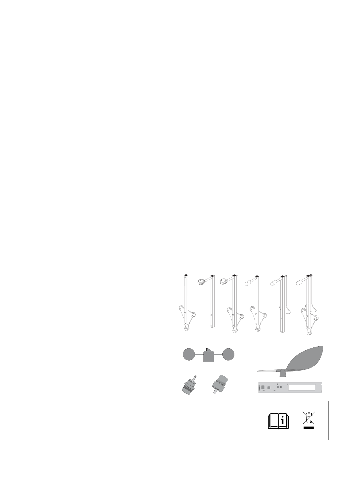
SENSOR MOUNTING ACCESSORIES (optional)
1. 2. 3. 4. 5. 6.
REPLACEMENT PARTS
WARRANTY (LIMITED)
The warranty period of NAVIS products is one year after the date of purchase. During limited warranty period any defective
product will be repaired or replaced with comparable product without charges. The claimed product will be repaired or replaced
only when returned to the store where it was purchased together with original invoice. Failure to follow these instructions may
invalidate the warranty. The limited warranty does not cover battery and damages of any kind including physical damages caused
accidentally or misuse of the product. NAVIS does not accept responsibility for any problems which may arise from applications
other than the product was designed for. Any liability for direct or indirect damage caused by product failure is excluded.
070219
__________________________________________________________________________________________________________________________________________
NAVIS elektronika d.o.o., Poljska cesta 11, SI-1241 Kamnik, [email protected]
1. Magnetic mounting assembly (for WS sensor)
2. Self-leveling mounting assembly (for WS sensor)
3. Magnetic self-leveling mounting assembly (for WS sensor)
4. Magnetic mounting assembly (for WSD sensor)
5. Self-leveling mounting assembly (for WSD sensor)
6. Magnetic self-leveling mounting assembly (for WSD sensor)
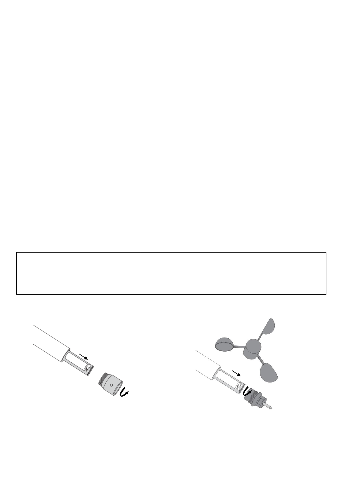
1. Spare anemometer cups
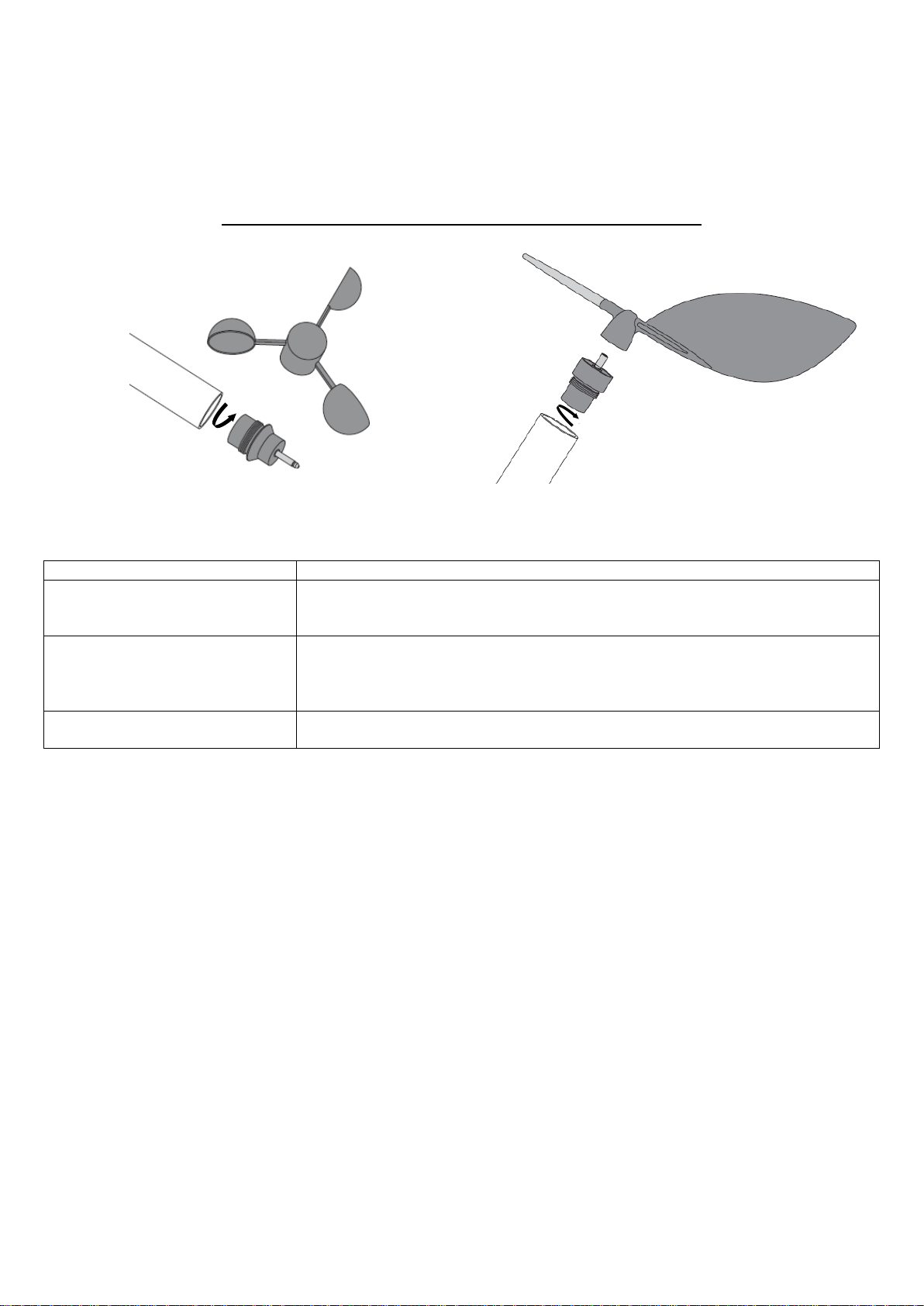
2. Spare wind vane
3. WS sensor head with bearings (for WS and WSD sensor)
4. WD sensor head with bearings (for WSD sensor)
5. WS sensor PCB
6. WSD sensor PCB
1 2
3 4
5, 6

This manual suits for next models

1

Other NAVIS Accessories manuals

NAVIS WL11/WS User manual

NAVIS

NAVIS WL11/WS User manual

NAVIS WS 010-2 User manual

NAVIS

NAVIS WS 010-2 User manual

Popular Accessories manuals by other brands

Etymotic Research Music PRO user manual

Etymotic Research

Etymotic Research Music PRO user manual

Vega PLICSMOBILE T81 operating instructions

Vega

Vega PLICSMOBILE T81 operating instructions

B.E.G. LUXOMAT PD1-M-2C Installation and operating instruction manual

B.E.G. LUXOMAT

B.E.G. LUXOMAT PD1-M-2C Installation and operating instruction manual

netvox R711 user manual

netvox

netvox R711 user manual

KNECHT HV 25-1 operating instructions

KNECHT

KNECHT HV 25-1 operating instructions

Stylies ELARA instruction manual

Stylies

Stylies ELARA instruction manual

Silvercrest B69PF manual

Silvercrest

Silvercrest B69PF manual

Manitowoc K00127 installation instructions

Manitowoc

Manitowoc K00127 installation instructions

Elko INELS Air Series manual

Elko

Elko INELS Air Series manual

StarTech.com ST122DVIA user guide

StarTech.com

StarTech.com ST122DVIA user guide

Manitowoc J-1800 Replacement manual

Manitowoc

Manitowoc J-1800 Replacement manual

Ace 3035466 (AC-6180) owner's manual

Ace

Ace 3035466 (AC-6180) owner's manual

Adata PV110 user manual

Adata

Adata PV110 user manual

Arctic Cove COOL CAVE MPK1180 Operator's manual

Arctic Cove

Arctic Cove COOL CAVE MPK1180 Operator's manual

Sony PMW10MD brochure

Sony

Sony PMW10MD brochure

Game Golf PRO user manual

Game Golf

Game Golf PRO user manual

Dimetix EDS-C manual

Dimetix

Dimetix EDS-C manual

Cornelius 000 PLUS installation manual

Cornelius

Cornelius 000 PLUS installation manual

manuals.online logo
manuals.online logoBrands
  • About & Mission
  • Contact us
  • Privacy Policy
  • Terms and Conditions

Copyright 2025 Manuals.Online. All Rights Reserved.