Techsage SpinJet 1000 User manual
Service guide March 2001 1
SpinJet 1000
Service Guide
Safety precautions
SpinJet 1000 is intended for use on the large format printer HP
DesignJet 1050C/1055CM (referred to as the printer) only. The in-
structions for installation and operation of both printer and SpinJet
1000 must be followed.
SpinJet is intended for permanent installation on the above mentioned
printer type. Normal single-sided printing is possible without removing
or tilting down the SpinJet 1000.
SpinJet 1000 is intended for operation with installed top cover and
mounted side covers.
The operator may remove the top cover during a jam removal. Only
specially trained personnel should carry out tasks for test or service
purposes, requiring operation in otherwise open and/or dismounted
condition.
The routines of inspection and replacement of wear and spare parts
must be followed. Always disconnect Power Mains before
disconnecting cables and electrical parts.
Connect SpinJet to Power Mains 100-120VAC or 200-240VAC,
50/60Hz, one phase and earth. Apply a Power Cord according to local
Voltages and Plugs. A UL Listed Power Cord rated minimum 10A,
125V is provided with SpinJet in areas where this apply.

Service guide March 2001 2
Table of Contents:
1. General .......................................................................................3
1.1 Functional test ............................................................................... 3
1.2 Fault finding ................................................................................... 3
Error codes ...................................................................................................3
Other trouble shooting ....................................................................................4
2. Wear and Spare Part replacement procedures ..................................8
2.1 General ......................................................................................... 8
2.2 Covers .......................................................................................... 9
5550 112 Cover 1 ........................................................................................9
5550 034 Assy, Cover 3 w/badge ...................................................................9
5550 035 Assy, Cover 2 w/keypad ..................................................................9
2.3 Drive and sensor components......................................................... 10
5551 004 Timing belt...................................................................................10
5551 066 Timing belt...................................................................................10
5550 005 Assy, motor w/pulley and connector ................................................11
5550 007 Assy, sensor/connector (PS01) ......................................................12
5551 001 Photo sensor (PS02) ....................................................................13
5551 001 Photo sensor (PS03) ....................................................................13
5550 026 Assy, harness #6 connector PCB to PS02-03.................................14
5551 062 Photo sensor left (PS04)...............................................................14
5551 063 Photo sensor right (PS05).............................................................14
5550 028 Assy, harness #10 connector PCB to PS04-05...............................14
2.4 Control system components ........................................................... 15
5551 073 Fuse ...........................................................................................15
5551 088 Fuse holder cap............................................................................15
5550 032 Assy, control system ....................................................................15
5550 048 PIC, programmed .........................................................................15
5550 197 Connector PCB............................................................................16
5550 027 Assy, harness #7 connector PCB to keypad ....................................16
5550 025 Assy, harness #5 connector PCB to motor 2 or 3 ...........................16
5550 038 Assy, harness #4 and #11 in supporting arm. .................................16
5550 030 Assy, harness #12 RS232 printer communication............................17
2.5 Mechanical components ................................................................. 17
5551 018 Gas spring...................................................................................17
5551 019 Bumper.......................................................................................17
5550 200 Bushing 4....................................................................................18
5550 166 Guide 5 .......................................................................................18
5550 021 Assy, Guide 6 ..............................................................................18
5550 196 Tool 1.........................................................................................18
5550 186 Flap ............................................................................................18
5550 199 Foil .............................................................................................19
5551 055 Tape ...........................................................................................19
5551 056 Tape ...........................................................................................19
5551 023 Spring.........................................................................................19
5550 174 Retainer 1 ...................................................................................19
5550 008 Pulley with clutch ..........................................................................19
5550 181 Encoder ......................................................................................20
1453 007 Bearing (on shafts) .......................................................................20
5550 020 Assy, hub with set screws (upper shaft) ..........................................20
5550 020 Assy, hub with set screws (lower shaft) ...........................................21
1453 007 Bearing (inside roller).....................................................................22
5550 011 Pulley with clutch ..........................................................................23
5550 055 Assy, Standoff with vibration damper .............................................23
5550 019 Boom guide with standoffs.............................................................23
5550 212 Spring guide 1 .............................................................................23
5550 036 Assy, Drum with spring, right ........................................................24
5550 037 Assy, Drum with spring, left ..........................................................24
1453 013 Bearing .......................................................................................25
5550 014 Brake with clutch..........................................................................26
5550 195 Bushing 2....................................................................................26
5550 208 Bushing 5....................................................................................26
5550 047 Assy, foot extension set................................................................26
3. Wear and Spare Parts list ........................................................... 27

Service guide March 2001 3
1. General
For information on installation procedure: Please see SpinJet Installation
Guide.
For information on specifications, normal use and operation: Please see
SpinJet Operator’s manual.
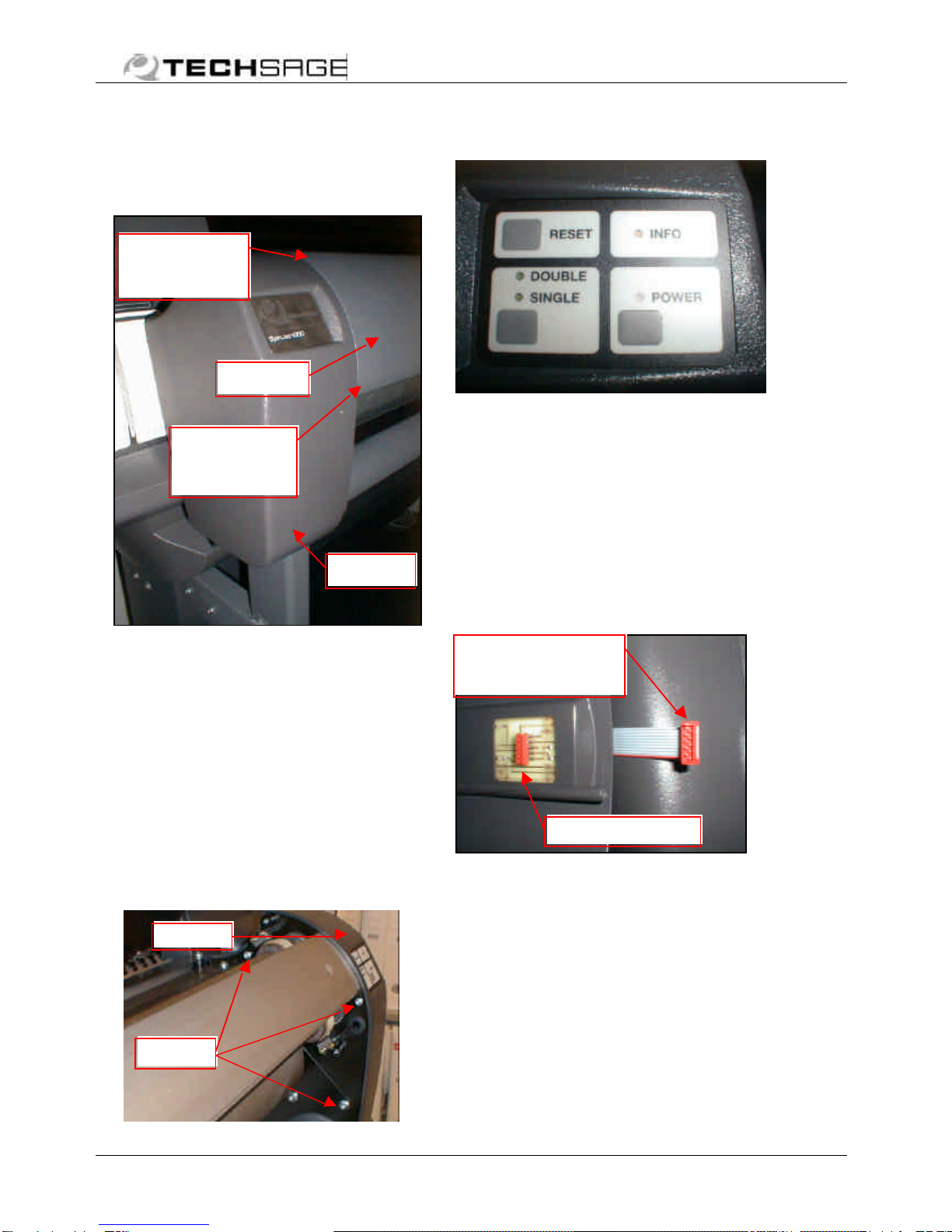
1.1 Functional test
In order to establish the existence of a possible problem and later the
effect of the corrective action taken, test the SpinJet as follows:
Connect the SpinJet control box to a power outlet.
Switch the box on with the rocker switch. A red light in the button
indicates that the control box is “on”.
Switch on the SpinJet by pressing the power button of the SpinJet
keyboard. Verify that the motors initialise and bring the system into the
“Single” state.
Press the mode button. Verify that the system switches to the
“Double” state and raises the flipper gate.
Install a SpinJet approved paper roll according to the user guide.
Run the test jobs of the software supplied with the product. Verify that
both sides are printed and the required front to back match is achieved.
If the match is inadequate, repeat the procedure of loosening the four
screws securing the printer to the printer base, moving the printer
slightly on its base and tightening the four screws again. Repeat until a
satisfactory result is achieved.
1.2 Fault finding
Error codes
Error
codeOccurs when Possible causes
Error01 Medium sensor on
when leaving OFF
state
Blocking object
Attenuator offset or rotated relative
to light emitter
Emitter defective
Receiver defective
Sensor harness defective
Harness #11 defective

Service guide March 2001 4
Error
codeOccurs when Possible causes
Error02 Gate sensor not on
in time
Motor 2 defective
Motor 2 harness #5 defective
Belt defective
Sensor defective
Sensor harness #6 defective
Harness #4 or #11 defective
Error03 Gate sensor not off
in time
Sensor defective
Sensor harness defective
Harness #4 or #11 defective
Error04 Boom sensor not on
in time
Motor 3 defective
Motor 3 harness #5 defective
Belt defective
Sensor defective
Sensor harness #6 defective
Harness #4 or #11 defective
Error05 Boom sensor not
off in time
Motor 3 defective
Motor 3 harness #5 defective
Belt defective
One way clutch defective
Sensor defective
Sensor harness #6 defective
Harness #4 or #11 defective
Error06 Paper feed encoder
does not reach
preset count value
in time
Sensor (right or left) defective
Sensor harness #10 defective
Harness #4 or #11 defective
Motor 1 defective
Belt defective
Other trouble shooting
SymptomsPossible causesRemedies
No light in control
box switch
Melted main fuse Replace fuse at inlet
module
Harness #11 defective
ReplaceNone of the LEDs
are lit in the SpinJet
keypad
and
Light in control box
switch
Control box component
failure
Replace control box
SpinJet does not
respond to the signal
from the printer to
go into double mode
Harness #12 defective Replace

Service guide March 2001 5
Symptoms Possible causes Remedies
The guide system
(leading to the sensor
light line) is damagedor
has a burr, which
obstructs the paper path
Find and remove
burr/damage
Roller/tire system has
too much friction or
resistance to rotate
Check bearings or
possible
interferences
Medium does not
reach paper sensor
Gate closes too tight on
Guide 2
or
The metal flag on the
right end of the gate is
bent
Straighten long leg
of the flag
Boom does not
maintain proper loop
shape of the sheet
during the first side
printing
and
Motor 3 runs
Suspension spring(s) is
damaged thus producing
friction in boom guides
Replace spring(s)
Boom suspension
springs curls during
first side printing
One way clutch defective Replace pulley/clutch
assembly of spring
drum shaft
One way clutch defective Replace pulley/clutch
assembly of feed
shaft
Sheet dropped by
SpinJet before being
fed into printer
Coil spring holding
central roller shaft
disengaged/lost
Reinstall/replace
Paper does not feed
into printer
and
Motor does not try
to feed
and
No error signal
Distance between right
and left encoder sensor
too long
Loosen, hold
together and fasten
Harness #4 defective
ReplacePaper does not feed
into printer
and
Motor does not try
to feed
and
Error code 06
displayed
Motor 1 defective Replace
One way clutch defective Replace pulley/clutch
assembly of feed
shaft
Paper does not feed
into printer
and
Motor does try to
feed
and
Tires do not run
and
Error code 06
displayed
Belt defective Replace

Service guide March 2001 6
Symptoms Possible causes Remedies
Sheet lead edge caught
by notches of Guide 1
Find and remove
burr/damage
Damage to foil on Guide
2
Find and remove
burr/damage
Faulty position of foil on
Guide 2
Paper does not feed
into printer
and
Motor and tires do
try to feed
Tires worn to too small
diameter
Replace hub/tire
assembly (8 pcs.)
Front unit too far away
from printer
Check and correct
position of the two
rubber bumpers
defining the distance
Sheet does not
reach blue line
Tires worn to too small
diameter
Replace hub/tire
assembly (8 pcs.)
Sheet overshoots
blue line by small
amount
Tire surface glazed or
contaminated (loss of
friction)
Replace hub/tire
assembly (8 pcs.)
Encoder sensor (right or
left) defective
Replace
Encoder sensor harness
#10 defective
Replace
Sheet overshoots
blue line by
approximately 50mm
Harness #11 defective Replace
Printer does not
respond to signal
from SpinJet to go
into sheet mode
Harness #12 defective Replace
Sheet pulled out of
printer again after
printer vacuum is
applied
One way clutch defectiveReplace pulley/clutch
assembly of feed
shaft
Printer unable to pull
in sheet from
SpinJet after printer
vacuum is applied
Printer vacuum too low Check printer
vacuum level and
vacuum system
seals
Insufficient pressure
from SpinJet against
printer platen
and
The last part of the
tilting to the lower
position achieved by
gravity (without
pushing)
Loss of pressure in gas
spring(s)
Identify spring(s),
which does not
produce 500N and
replace
Noisy drives Wrong belt tension Readjust belt
tension according to
replacement
procedures for
5551 004 and 066
in section 2.3.

Service guide March 2001 7
Where possible, verify the hypothesis regarding the cause of an
experienced problem by trying to replace the suspect part or system.
Make only onereplacement between these tests and go back to the
originally fitted part or system, when there is no effect of the
replacement.
All sensors are using an optical principle, where the effect is that of a
light path being intersected by a moving part or by the medium. All
sensors are equipped with monitoring LED’s with the following functions:
PS01: Green LED on means that the signal is stable and
unambiguous.
Red/orange LED on means light path is cut by an object
(“dark”).
PS02-05: A red LED means, that the light path is not cut by an
object (opposite of “dark”).
These functions serve to help identifying certain sensor related faults
before trying to replace the sensor itself.
Service guide March 2001 8
2. Wear and Spare Part replacement
procedures
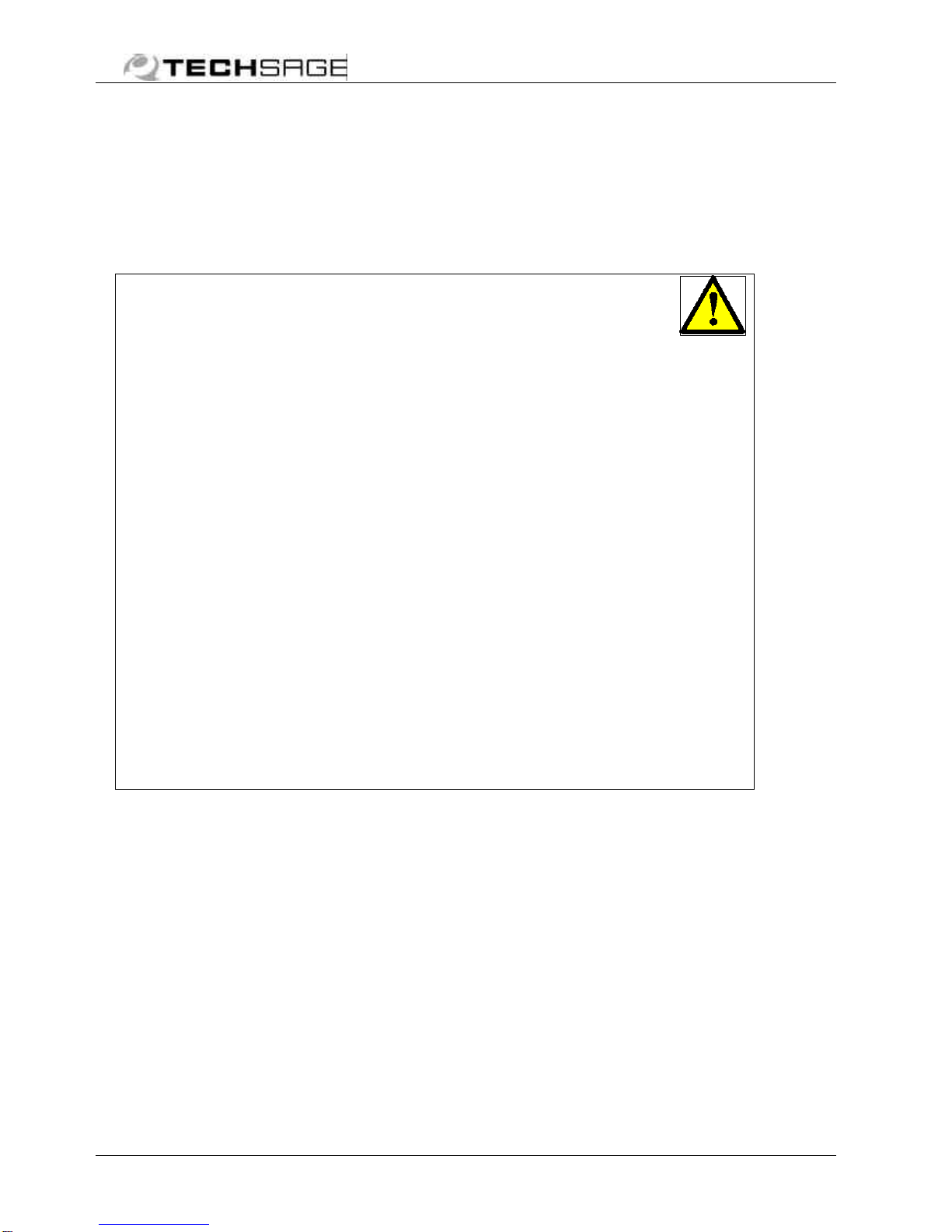
2.1 General
Replacement procedures require
that the SpinJet is mounted on a
printer or supported similarly. In
general replacements require
covers to be removed first.
Further for general reference,
Guide 2 and Guide 5 are identified
in picture below.
In order to maintain internal
accuracy of the unit, the screws
of Beam 1 and Guide 1 should
never be loosened.
Recommended tools:
§Torx screwdrivers T10, T15
and T20
§T25 (provided with HP
Printer)
§Straight blade screwdrivers
(small sizes)
§Thin blade knife
§Pair of pliers (pointed)
§Soft head hammer
§M5 screw, length 12 mm
min. (provided with the
SpinJet)
§PIC extractor
§Antistatic wristband
Guide 1
Beam 1
Cover 1
Cover
3
Cover 2
Guide
5
Guide 2
Service guide March 2001 9
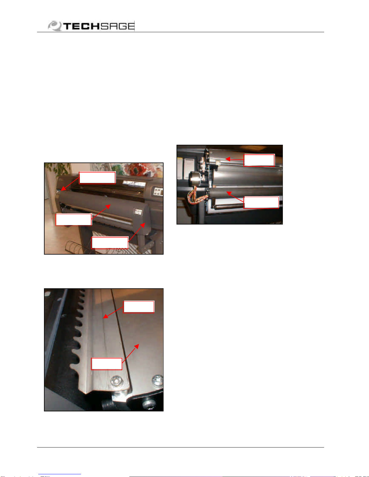
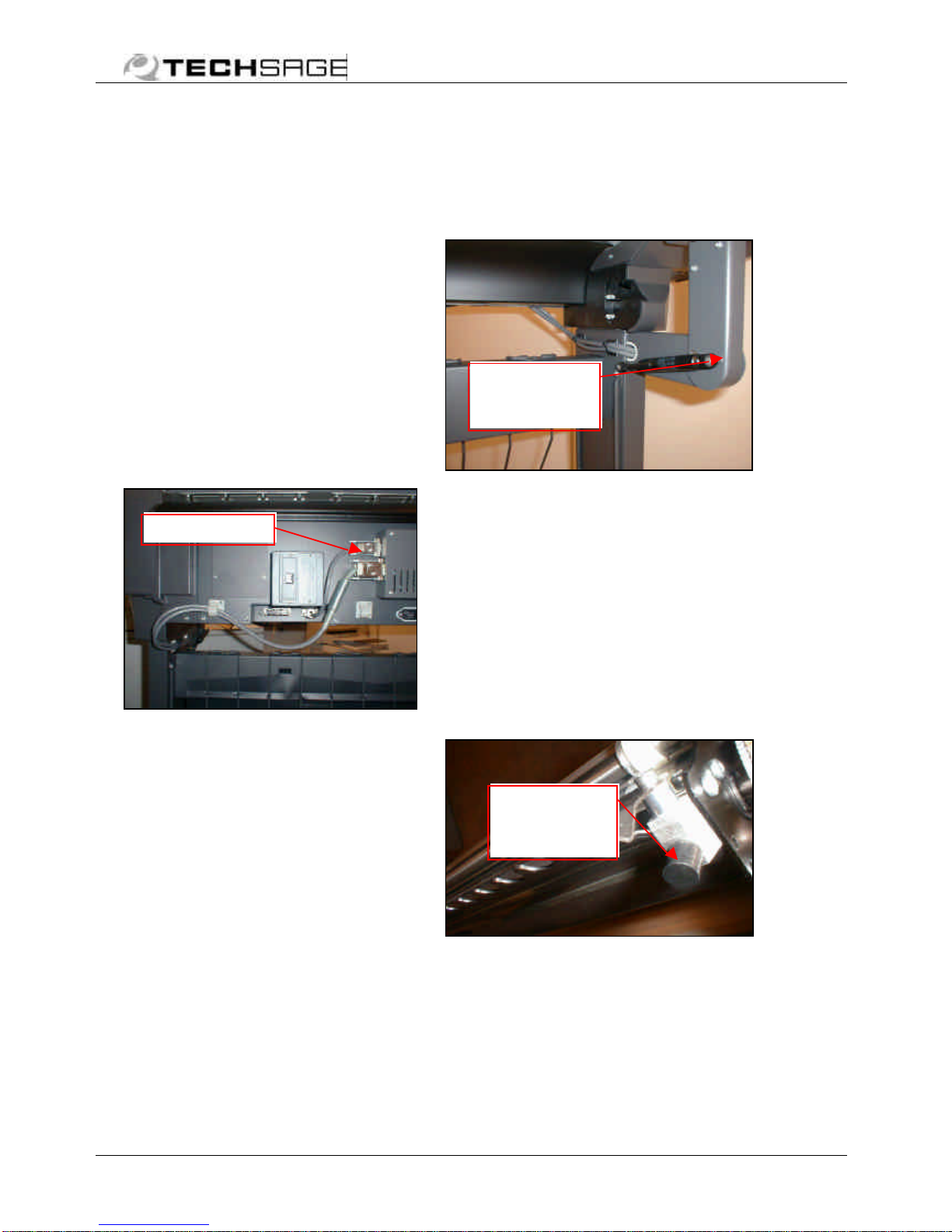
2.2 Covers
5550 112 Cover 1
Release at lower studs first by
gently pulling outwards and lift off
at upper studs. Install in reverse
order.
5550 034 Assy, Cover 3
w/badge
5550 035 Assy, Cover 2
w/keypad
The side covers are fastened with
3 screws each (see picture).
Remove Cover 1 to get access to
the two upper screws.
Cover 3 comes with the badge
and Cover 2 with the keypad.
5550 027, Assembly, harness
#7, connector PCB to keypad
(not included in 5550 035) must
be disconnected from the keypad
in order to allow Cover 2 to be
put aside.
Note the little orientation tab of
the connector when refitting.
Take care to fit harnesses well
inside when installing covers.
Lower stud
inside side
plate
Upper stud
inside side
plate
Cover 1
Cover 3
Inside of keypad
Tail of 5550 027
(orientation tab indi-
cated by the arrow)
Cover 2
3 screws

Service guide March 2001 10
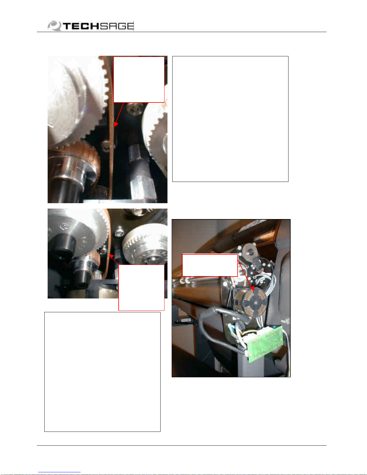
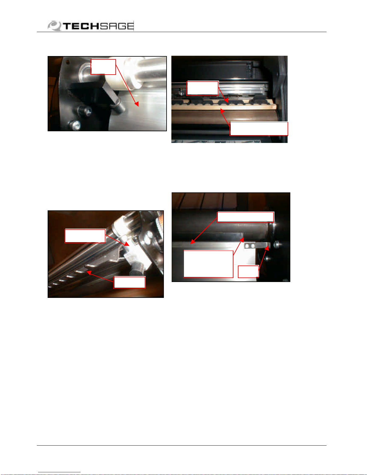
2.3 Drive and sensor components
5551 004 Timing belt
5551 066 Timing belt
WARNING!
Always support and lower the
boom (picture) by hand when
loosening and removing timing
belt ofmotor 3.
Remember to loosen the 3 motor
standoff screws (picture) before
replacement. Reapply correct
timing belt tension according to
below procedures.
Motor 1 and 2
Adjustment of timing belt
5551 004:
With the motor turned off and
all 3 motor standoff screws
loosened apply a load of 2N
near the tip of the screwdriver
engaging the TOP screw and
tighten screw (picture). Then
tighten the 2 other screws.
The load can be provided by a
spring balance or by hanging a
200g mass load (e.g. a stack of
sheets)on the screwdriver.
Make sure the belt is not
transmitting torque during the
procedure.
55551 066
(motor 3)
55551 004
(motor 1+2)
55551 066
(motor 3)
55551 004
(motor 1+2)
Load 2N (200 g)
Motor standoff
screw
Lowered boom
Service guide March 2001 11
Motor 3
Adjustment of timing belt
5551 066:
Make sure the belt is not
transmitting torque during the
procedure (lower the Boom to
the bottom position).
With the motor turned off
loosen all 3 motor standoff
screws (inside the side plate).
Move the unit until the timing
belt has no preload and
minimum slack (picture) and
tighten the screws.
Test the tension by turning on
the SpinJet, switch it to the
Double mode and intersect the
beam of PS01. Motor 3 will
now lower the boom until the
Reset-button is activated.
Too much tension gives more
noise and possibly stalling
motor during lowering.
Too much slack will cause the
belt to disengage the teeth of
the motor pulley at a slight load
of the Boom during raising.
Repeat the positioning if
required.
5550 005 Assy, motor
w/pulley and connector
Motor 1, 2 and 3 are identical.
Motor with
pulley and
harness
Timing belt
5551 066
(motor 3)
with
appropriate
slack
Timing belt
5551 066
(motor 3)
with too
much
slack.
Service guide March 2001 12
To disconnect motor 2 or 3 (left
side of unit) first disconnect
motor harness at connector PCB
(right side), then pull the harness
just enough to gain access to the
connectors.
Make sure to lower boom before
removing timing belt on motor 3.
Loosen 3 screws on the motor
flange and remove the timing belt.
Replace motor, tighten 3 screws
on motor flange and reconnect
motor harnesses.
Adjust timing belt tension as
described in previous section.
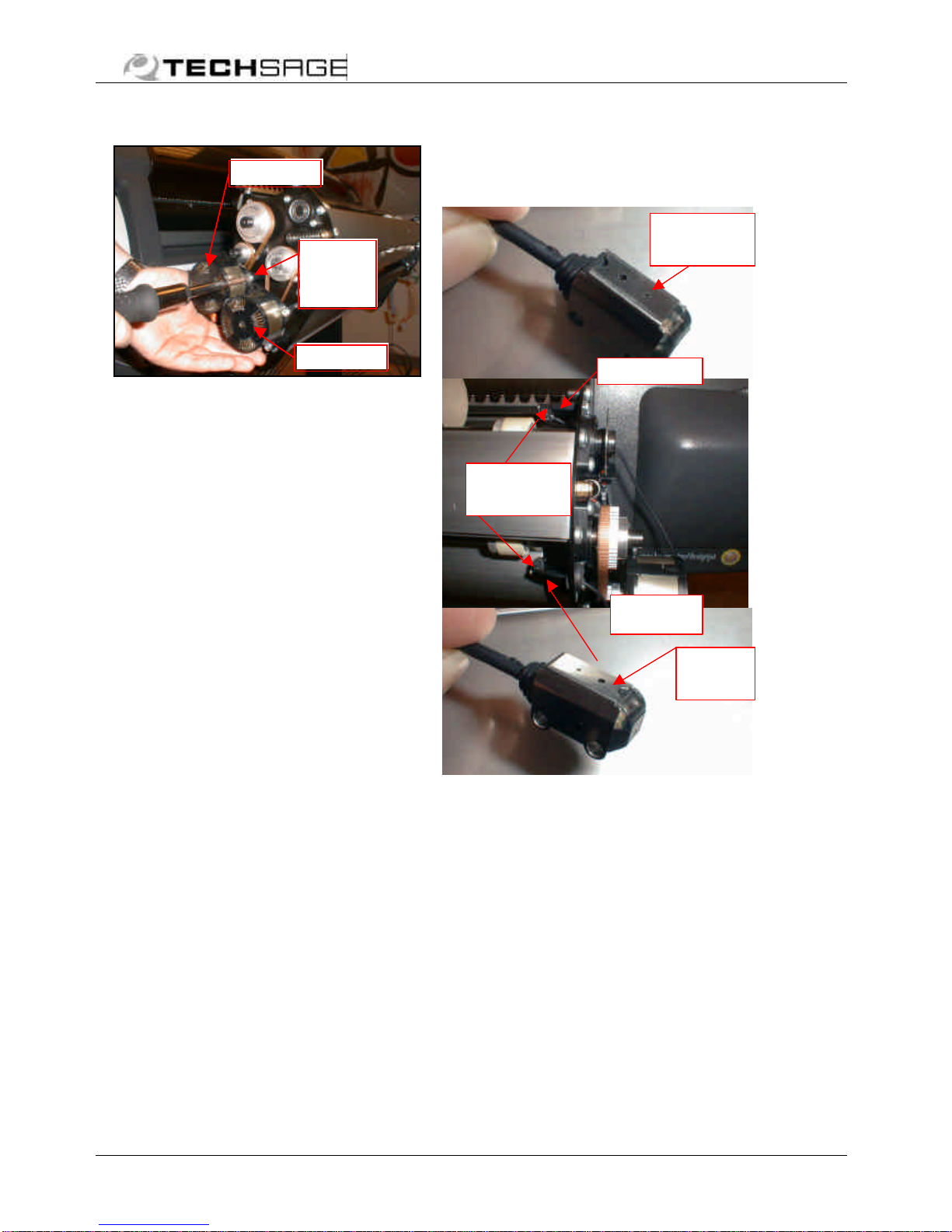
5550 007 Assy,
sensor/connector (PS01)
Disconnect assy from the
connector PCB, loosen screws of
emitter and receiver and remove
the hole grommets and the assy.
Reassemblein reverse order. Make
sure to position holes (ø0.5 and
ø1) of sensitivity attenuators
according to above picture.
Motor
flange
screw
Motor
2
Motor
3
Hole ø
0.5 mm
Receiver
Unscrew
this side
Emitter
Hole ø
1 mm
Service guide March 2001 13
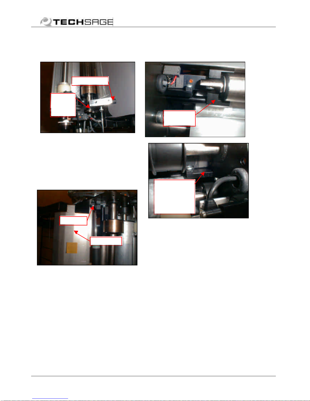
5551 001 Photo sensor
(PS02)
Dismount Guides 2 and Guide 5 as
well as Console 2 (picture).
Dismounting of the boom shaft
pulley on the left side is required.
Refer to section 5550 008 (pulley)
and 5550 066.
Swing down Guide 4, loosen,
remove and disconnect PS02.
Reassemble in reverse order. Make
sure to adjust to correct timing
belt tension as previously
described.
5551 001 Photo sensor
(PS03)
Lower boom by hand and
dismount the boom guide. Loosen
and remove PS03 with its pillar.
Disconnect and replace PS03.
Reassemble in reverse order.
PS03.
Screws of
pillar are
outside side
plate.
PS 02
Console 2
PS 02
located
inside
Guide 4
Boom
guide
Service guide March 2001 14
5550 026 Assy, harness #6
connector PCB to PS02-03
Disassemble PS02 or 03 as
described in the previous
sections.
Unscrew connector PCB,
disconnect harness and withdraw
it through the side plate.
Reassemble in reverse order.
Make sure to reconnect EMC
ground straps with the same
connector board securing screw.
5551 062 Photo sensor left
(PS04)
5551 063 Photo sensor
right (PS05)
5550 028 Assy, harness #10
connector PCB to PS04-05
Replacement of encoder sensors
PS04 and 05 requires removing of
the sensor fastening screws.
Common harness #10 is plugged
into sensor.
It is easier to disconnect the
connector from the sensor, when
the sensor is removed from the
pillar.
Important: Keep the two sensors
in close contact with each other
when re-installing.
To replace harness, first loosen
screws of the connector PCB.
Make sure to reconnect EMC
ground straps when reassembling.
PS04
PS05
Harness #6
(2 pcs.)
Service guide March 2001 15
2.4 Control system
components
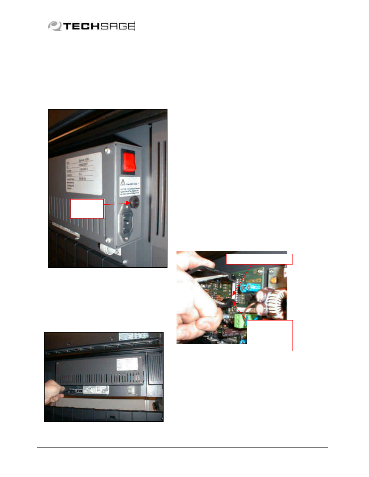
5551 073 Fuse
5551 088 Fuse holder cap
Turn fuse cap with screwdriver
and remove fuse and cap.Replace
with fuse rated “250V 3.15A T
(ø5 x 20 mm) only!
5550 032 Assy, control
system
Disconnect all harnesses before
removal. Control box is fastened
to printer by 2 screws below box.
Reconnect as described in
installation guide (male/female
coding makes it impossible to
interchange the two 15-pin
connectors).
5550 048 PIC, programmed
Component safety precautions
Handling:
•Avoid touching the legs,
which are susceptible to
static electricity
•Keep the legs mutually
“grounded” with conductive
material for storing/shipping
Exchange:
Note the position of the half-circle
notch on the body of the PIC: It
should be pointing downwards in
the control box when mounted on
the printer.
Before replacement switch off
power completely by removing the
supply cord. Replace the PIC
using a PIC extractor (tool) as
shown in picture.
Especially if tool is unavailable,
take care to lever out and install
the PIC as parallel as possible,
thus avoiding bending of the legs.
Fuse
holder
PIC,
programm
ed
Take hold of
both ends
with the PIC
extractor

Service guide March 2001 16
5550 197 Connector PCB
Replace connector PCB by
loosening it from the 2 standoffs
and disconnect all harnesses
(picture below).
Make sure to reconnect EMC
ground strap from harness #4
and #11 with same connector
board securing screw when
reassembling.
5550 027 Assy, harness #7
connector PCB to keypad
Dismount connector PCB and
replace harness. The keypad is
part of the cover spare part
(5550 035).
5550 025 Assy, harness #5
connector PCB to motor 2 or
3
Dismount connector PCB and
disconnect harness #5.Withdraw
it through the beam and disconnect
at motor end (connectors are
located inside beam when
assembled). Reassemble in reverse
order.
5550 038 Assy, harness #4
and #11 in supporting arm.
Assembly comprises assembled
pillar, console and gas spring with
motor and signal harnesses:
§5550 024 Assy, harness #4
main PCB to connector PCB,
motor
§5550 029 Assy, harness #11
main PCB to connector PCB,
signal
Replacement requires removal of
the entire mechanical unit.
Disconnect harnesses at control
box and detach them from the an-
chors on the clamp.
Connector
PCB
Harness
#5 (2 pcs.)
Harness #4
and #11
strapped on
clamp.
Supporting
arm assy
Location
of screws
(4 pcs.
T20)
Service guide March 2001 17
Remove the 4 screws holding the
SpinJet to the clamps(picture)
and lift off the unit.
Dismount connector PCB,
disconnect harnesses and
unscrew supporting arm assembly
from side plate.
Reassemble in reverse order,
adjust and test the unit according
to section 4 and 6 of the
Installation Guide.
5550 030 Assy, harness
#12 RS232 printer
communication
Replacement follows directly from
the picture. Assure that both
SpinJet and Printer are turned off
during replacement.
2.5 Mechanical compo-
nents
5551 018 Gas spring
Replace one gas spring at a time
only. Keep SpinJet in upright
position and release retainers at
both ends. Depress gas spring
slightly with a cramp/clamp to
unload the bearing. Reassemble in
reverse order.
Caution: Depressing gas spring
requires a force of 500 Newton!
5551 019 Bumper
Support at
printer front
(2 pcs.)
Depress ends
with clamp or
vice.
Harness #12
Service guide March 2001 18
Two bumpers are located on the
unit at points of contact with the
printer front and one at the gate.
Unscrew and reinstall bumpers by
hand.
5550 200 Bushing 4
5550 166 Guide 5
See picture for replacement.
5550 021 Assy, Guide 6
5550 196 Tool 1
Guide 6 is located on lower edge
of the printer window.
The spare part comes supported
by a wooden installation rail. Keep
Guide 6 in the rail during handling.
Tool 1 isused for control of the
gap under the guide.
For information on installation
procedure: Please see SpinJet
Installation Guide.
5550 186 Flap
The transparent flap, supplied with
an adhesive strip, is located on the
inside of the gate.
Replace flap by gently pulling it off,
cleaning gate with ethanol and
apply new flap. Assure flap
protrudesfrom gate as shown, is
aligned with the flag at the right
end and is firmly pressed to the
surface of the gate.
Flap
must
protrude
11.8±1.5 mm
from gate
Flag
Gate
Guide 5
Bushing 4
Adhesive strip
Installation rail
Guide 6

Service guide March 2001 19
5550 199 Foil
The foil is located on Guide 4,
where the sheet exitsthe unit.
Spare part is supplied with an
adhesive strip.
Replace foil by gently pulling it off,
cleaning guide with ethanol and
apply new foil as specified on
picture.
5551 055 Tape
5551 056 Tape
5551 055 is a common 19 mm
3M Scotch Magic Tape and is not
supplied as a spare part. 5551
056 is supplied to a pre-cut
length.
For information on installation
procedure: Please see SpinJet
Installation Guide.
5551 023 Spring
Springs are located at both roller
ends (see next picture).
Important: Do not remove or
reinstall springs by grabbing the
body of the spring, as this may
damage the preload (no visible
damage!)
Replace by gently lifting the spring
eyelet off the stud and the shaft
end, using a pair of pliers (pointed).
Roller is retained by clearance
holes in side plates.
5550 174 Retainer 1
The press fit retainers are located
on the shafts for the one way
clutches, one on the right side (see
next picture) and two on the left
side of unit. Pull off with an M5-
screw and reinstall by gently
tapping on the end of the retainer.
5550 008 Pulley with clutch
Foil
No
t to exceed
end edge
Press the adhesive
strip
firmly on
Foil must
protrude 9.1±0.5
mm
from
G
uide 4
5551 055
5551 056
Spring
Retainer 1
M5-hole in
center
5550 008

Service guide March 2001 20
This pulley is located on the paper
feed shaft end close to motor 1.
Remove retainer and timing belt
as described in previous sections.
Replace pulley, reinstall retainer
and timing belt and readjust timing
belt tension as described in
previous section.
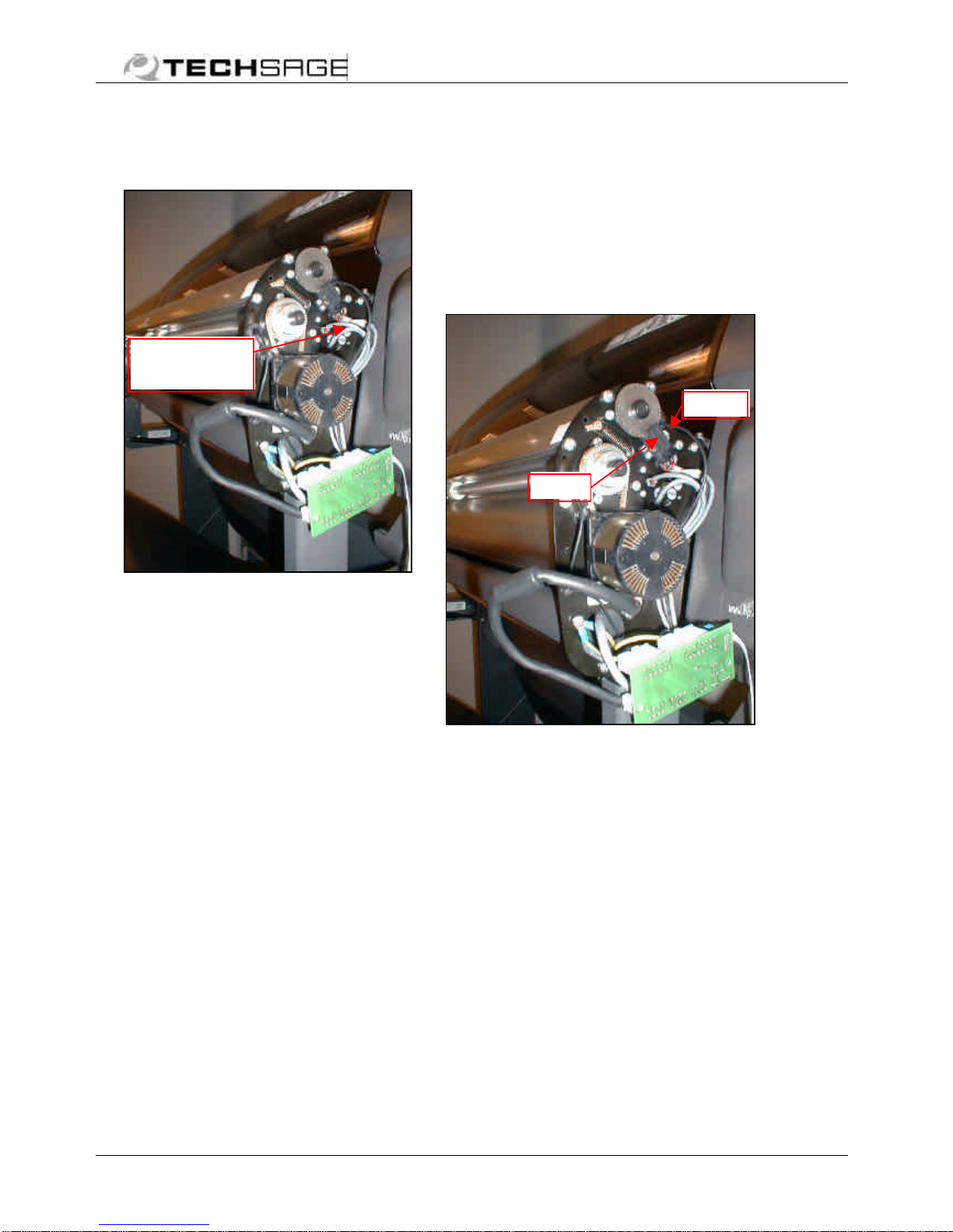
5550 181 Encoder
Remove sensors PS04 and PS05
(refer to earlier section).
If only the disc needs
replacement, slide off the retainer
and the encoder using a thin blade
and thin screwdrivers.
Press on new encoder disc and
retainer and reinstall sensors.
If the assembly including the hub
is to be removed, see the
following.
1453 007 Bearing (on
shafts)
Dismount springs from roller ends
(previously described under
5551023).
To get access to the upper shaft,
first remove encoder unit located
on right side plate. Insert two
screwdrivers in the groove of the
encoder hub (picture) and lever off
the encoder disc assembly (with
hub).
To get access to the lower shaft,
first remove the pulley on the
right shaft end (refer to earlier
section, 5550 008). Also remove
pulley 4 on the roller shaft
(picture above) in order to get
access to the screwsofHousing
2.
Loosen and remove Housing 2
and/or 3 with bearing from shaft
end and side plate. Slide bearing
out of Housing. Reinstall in
reverse order.
5550 020 Assy, hub with
set screws (upper shaft)
Bearing
Housing 3
Housing 2
Shaft 8
Roller end
Pulley 4
Hub
Encoder
Encoder
PS04 + 05
Table of contents
Other Techsage Printer Accessories manuals

Popular Printer Accessories manuals by other brands


Xerox
Xerox 5500DN - Phaser B/W Laser Printer manual

Konica Minolta
Konica Minolta HT-502 installation manual

NEC
NEC SUPERSCRIPT 4400 SERIES user guide

Kodak
Kodak XLS 8600 PS user guide

Lexmark
Lexmark 20T3600 - T 620 B/W Laser Printer quick reference

HP
HP Designjet 8000s Take-Up Reel Kit installation guide