TECHTOP TD310 Series Instruction manual


TD310 Series VFD Preface
i
Preface
Thanks for choosing our products.
TD310 series variable-frequency drives (VFDs) are high performance open loop vector VFDs for
controlling asynchronous AC induction motors and permanent magnet synchronous motors. Applying
the most advanced non-velocity sensor vector control technology which keeps pace with the leading
international technology and DSP control system, our products enhances its reliability to meet the
adaptability to the environment, customized and industrialized design with more optimized functions,
more flexible application and more stable performance.
The control performance of TD310 series VFDs is as outstanding as that of the leading sophisticated
VFDs on worldwide market. TD310 series VFDs integrate the drive of asynchronous motors and
synchronous motors, torque control and speed control, meeting the high performance requirement of
the customer applications and stepping on the unique incorporated VFDs with superexcellent control
functions in this circle. Simultaneously, comparing with the other kinds, TD310 series VFDs can adapt
to worse grid, temperature, humidity and dust with a better performance of anti-tripping and improved
reliability.
TD310 series VFDs apply modularized design to meet the specific demand of customers, as well as
the demand of the whole industry flexibly and follow the trend of industrial application to the VFDs on
the premise of meeting general need of the market. Powerful speed control, torque control, simple
PLC, flexible input/output terminals, pulse frequency given, traverse control can realize various
complicate high-accuracy drives and provide integrative solution for the manufacturers of industrial
devices, which contributes a lot to the cost reducing and improves reliability.
TD310 series VFDs can meet the demand of environmental protection which focuses on low noise
and weakening electromagnetic interference in the application sites for the customers.
This manual provides installation and configuration, parameters setting, fault diagnoses and daily
maintenance and related precautions to customers. Please read this manual carefully before the
installation to ensure a proper installation and operation and high performance of TD310 series VFDs.
If the product is ultimately used for military affairs or manufacture of weapon, it will be listed on the
export control formulated by Foreign Trade Law of the People's Republic of China. Rigorous
review and necessary export formalities are needed when exported.
Our company reserves the right to update the information of our products.

TD310 Series VFD Contents
ii
Contents
Preface............................................................................................................................................i
Contents.........................................................................................................................................ii
1 Safety precautions......................................................................................................................1
1.1 What this chapter contains ....................................................................................................1
1.2 Safety definition ....................................................................................................................1
1.3 Warning symbols...................................................................................................................1
1.4 Safety guidelines...................................................................................................................2
2 Quick start...................................................................................................................................5
2.1 What this chapter contains....................................................................................................5
2.2 Unpacking inspection............................................................................................................5
2.3 Application confirmation ........................................................................................................5
2.4 Environment..........................................................................................................................5
2.5 Installation confirmation.........................................................................................................6
2.6 Basic commissioning.............................................................................................................6
3 Product overview........................................................................................................................7
3.1 What this chapter contains ....................................................................................................7
3.2 Basic principles.....................................................................................................................7
3.3 Product specification.............................................................................................................8
3.4 Nameplate..........................................................................................................................10
3.5 Type designation key...........................................................................................................10
3.6 Rated specifications............................................................................................................ 11
3.7 Structure diagram................................................................................................................13
4 Installation guidelines...............................................................................................................15
4.1 What this chapter contains ..................................................................................................15
4.2 Mechanical installation........................................................................................................15
4.3 Standard wiring...................................................................................................................20
4.4 Layout protection ................................................................................................................29
5 Keypad operation procedure....................................................................................................31
5.1 What this chapter contains..................................................................................................31
5.2 Keypad ...............................................................................................................................31
5.3 Keypad displaying...............................................................................................................33
5.4 Keypad operation................................................................................................................34
6 Function parameter...................................................................................................................36
6.1 What this chapter contains ..................................................................................................36
6.2 TD310 function parameters.................................................................................................36
7 Basic operation instruction.................................................................................................... 113
7.1 What this chapter contains ................................................................................................ 113
7.2 First powering on .............................................................................................................. 113
7.3 Vector control.................................................................................................................... 117

TD310 Series VFD Contents
iii
7.4 SVPWM control.................................................................................................................120
7.5 Torque control...................................................................................................................125
7.6 Parameters of the motor....................................................................................................129
7.7 Start–up and stop control...................................................................................................132
7.8 Frequency setting..............................................................................................................136
7.9 Analog input......................................................................................................................140
7.10Analog output..................................................................................................................142
7.11 Digital input .....................................................................................................................146
7.12 Digital input.....................................................................................................................152
7.13 Simple PLC.....................................................................................................................156
7.14 Multi–step speed running ................................................................................................158
7.15 PID control......................................................................................................................160
7.16 Traverse running.............................................................................................................165
7.17 Pulse counter..................................................................................................................166
7.18 Fixed–length control........................................................................................................167
7.19 Fault procedure...............................................................................................................168
8 Fault tracking..........................................................................................................................171
8.1 What this chapter contains ................................................................................................171
8.2 Alarm and fault indications.................................................................................................171
8.3 How to reset......................................................................................................................171
8.4 Fault history......................................................................................................................171
8.5 Fault instruction and solution.............................................................................................171
8.6 Common fault analysis......................................................................................................176
9 Maintenance and hardware diagnostics................................................................................181
9.1 What this chapter contains ................................................................................................181
9.2 Maintenance intervals .......................................................................................................181
9.3 Cooling fan........................................................................................................................183
9.4 Capacitors.........................................................................................................................184
9.5 Power cable......................................................................................................................185
10 Communication protocol......................................................................................................186
10.1 What this chapter contains ..............................................................................................186
10.2 Brief instruction to Modbus protocol.................................................................................186
10.3 Application of the VFD.....................................................................................................186
10.4 RTU command code and communication data illustration................................................192
10.5 Common communication fault.........................................................................................205
Appendix A Extension card.......................................................................................................206
A.1 What this chapter contains................................................................................................206
A.2 PROFIBUS extension card ...............................................................................................206
A.3 CANopen optional cards...................................................................................................221
Appendix B Technical data........................................................................................................222
B.1 What this chapter contains................................................................................................222

TD310 Series VFD Contents
iv
B.2 Ratings.............................................................................................................................222
B.3 Grid specifications ............................................................................................................224
B.4 Motor connection data ......................................................................................................224
B.5 Applicable standards.........................................................................................................224
B.6 EMC regulations...............................................................................................................225
Appendix C Dimension drawings..............................................................................................227
C.1 What this chapter contains................................................................................................227
C.2 Keypad structure ..............................................................................................................227
C.3 VFD structure...................................................................................................................228
C.4 Dimensions for VFDs........................................................................................................228
C.5 Dimensions for VFDs of AC 3PH 520V(–10%)–600V(+10%).............................................233
Appendix D Peripheral options and parts.................................................................................234
D.1 What this chapter contains................................................................................................234
D.2 Peripheral wiring...............................................................................................................234
D.3 Power supply....................................................................................................................235
D.4 Cables..............................................................................................................................235
D.5 Fuse.................................................................................................................................240
D.6 Reactors...........................................................................................................................241
D.7 Filters...............................................................................................................................242
D.8 Braking system.................................................................................................................242
Appendix E Further information................................................................................................247
E.1 Product and service inquiries............................................................................................247
E.1 Feedback on TECHTOP VFD manuals .............................................................................247
TD310 Series VFD Safety precautions
-1-
1 Safety precautions
1.1 What this chapter contains
Please readthis manualcarefully and followall safety precautions before moving, installing, operating
and servicing the variable-frequency drive (VFD). If ignored, physical injury or death may occur, or
damage may occur to the devices.
If any physical injury or death or damage to the devices occurs due to neglect of the safety
precautions in the manual, our company will not be responsible for any damages and we are not
legally bound in any manner.
1.2 Safety definition
Danger:
Serious physical injury or even death may occur if related
requirements are not followed
Warning:
Physical injury or damage to the devices may occur if related
requirements are not followed
Note:
Physical hurt may occur if related requirements are not followed
Qualified
electricians:
People working on the device should take part in professional
electrical and safety training, receive the certification and be
familiar with all steps and requirements of installing,
commissioning, operating and maintaining the device to avoid any
emergency.
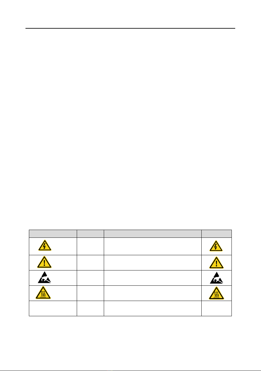
1.3 Warning symbols
Warnings caution you about conditions which can result in serious injury or death and/or damage to
the equipment, and advice on how to avoid the danger. Following warning symbols are used in this
manual:
Symbols
Name
Instruction
Abbreviation
Danger
Electrical
Danger
Serious physical injury or even death may
occur if related requirements are not followed
Warning
General
danger
Physical injury or damage to the devices may
occur if related requirements are not followed
Do not
Electrostatic
discharge
Damage to the PCBA board may occur if
related requirements are not followed
Hot sides
Hot sides
Sides of the device may become hot. Do not
touch.
Note
Note
Physical hurt may occur if related
requirements are not followed
Note

TD310 Series VFD Safety precautions
-2-
1.4 Safety guidelines
Only qualified electricians are allowed to operate on the VFD.
Do not carry out any wiring, inspection or components replacement when the
power supply is applied. Ensure all input power supply is disconnected before
wiring and checking and always wait for at least the time designated on the VFD
or until the DC bus voltage is less than 36V. The table below describes the
waiting time:
VFD model
Minimum waiting time
220V
0.75kW-55kW
(1HP–5HP)
5 minutes
460V
1.5kW–110kW
(2HP–150HP)
5 minutes
132kW–315kW
(175HP–425HP)
15 minutes
350kW–500kW
(475HP–675HP)
25 minutes
575V
18.5kW–110kW
(25HP–150HP)
5 minutes
Do not refit the VFD unless authorized; otherwise fire, electric shock or other
injury may occur.
The base of the radiator may become hot during running. Do not touch to avoid
hurt.
The electrical parts and components inside the VFD are electrostatic. Take
measurements to avoid electrostatic discharge during related operation.
1.4.1 Delivery and installation
Install the VFD on fire-retardant material and keep the VFD away from
combustible materials.
Connect the braking optional parts (brake resistors, brake units or feedback
units) according to the wiring diagram.
Do not operate on the VFD if there is any damage or components loss to the
VFD.
Do not touch the VFD with wet items or body, otherwise electric shock may
occur.
Solid State motor overload protection reacts when reaches 150% of FLA.
Drives have no provision for motor over temperature protection.
Note:
Select appropriate moving and installing tools to ensure a safe and normal running of the VFD and
avoid physical injury or death. For physical safety, the erector should take some mechanical
protective measurements, such as wearing exposure shoes and working uniforms.

TD310 Series VFD Safety precautions
-3-
Ensure to avoid physical shock or vibration during delivery and installation.
Do not carry the VFD by its cover. The cover may fall off.
Install away from children and other public places.
The VFD cannot meet the requirements of lowvoltage protection in IEC61800-5-1 if the altitude of
installation site is above 2000m.
Use the VFD on appropriate condition (See chapter Installation Environment).
Don't allow screws, cables and other conductive items to fall inside the VFD.
The leakage current of the VFD may be above 3.5mA during operation. Proper and reliable
grounding is essential before connecting to power supply. Ground with proper techniques and
ensure the grounding resistor is less than 10Ω. The conductivity of PE grounding conductor is the
same as that of the phase conductor (with the same cross sectional area).
R, S and T are the input terminals of the power supply, while U, V and W are the motor terminals.
Please connect the input power cables and motor cables with proper techniques; otherwise the
damage to the VFD may occur.
1.4.2 Commissioning and running
Disconnect all power supplies applied to the VFD before the terminal wiring and
wait for at least the designated time after disconnecting the power supply.
High voltage is present inside the VFD during running. Do not carry out any
operation except for the keypad setting.
The VFD may start up by itself when P01.21=1. Do not get close to the VFD and
motor.
The VFD cannot be used as “Emergency-stop device”.
The VFD cannot be used to break the motor suddenly. A mechanical braking
device should be provided.
Besides the above items, check to ensure the following ones before the
installation and maintenance during the running of the permanent synchronous
motor:
1. All input power supply is disconnected (including the main power supply and
the control power supply).
2. The permanent magnet synchronous motor has stopped running and
measured to ensure the output voltage of the VFD is less than 36V.
3. The waiting time of the permanent magnet synchronous motor after stopping
is no less than the time designated and measure to ensure the voltage
between + and –is less than 36V.
4. Ensure the permanent magnet synchronous motor does not rotate again
because of the external load. It is recommended to install effectively external
braking devices or disconnect the electric wiring between the motor and the
VFD directly.

TD310 Series VFD Safety precautions
-4-
Note:
Do not switch on or off the input power supply of the VFD frequently.
For VFDs that have been stored for a long time, check and fix the capacitance and try to run it
again before utilization (see Maintenance and Hardware Fault Diagnose).
Cover the front board before running, otherwise electric shock may occur.
1.4.3 Maintenance and replacement of components
Only qualified electricians are allowed to perform the maintenance, inspection,
and components replacement of the VFD.
Disconnect all power supplies to the VFD before the terminal wiring. Wait for at
least the time designated on the VFD after disconnection.
Take measures to avoid screws, cables and other conductive matters to fall
into the VFD during maintenance and component replacement.
Note:
Please select proper torque to tighten screws.
Keep the VFD, parts and components away from combustible materials during maintenance and
component replacement.
Do not carry out any isolation and pressure test on the VFD and do not measure the control
circuit of the VFD by megameter.
Carry out a sound anti-electrostatic protection to the VFD and its internal components during
maintenance and component replacement.
1.4.4 What to do after scrapping
There are heavy metals in the VFD. Deal with it as industrial effluent.

TD310 Series VFD Quick start
-5-
2 Quick start
2.1 What this chapter contains
This chapter mainly describes the basic guidelines during the installation and commissioning
procedures on the VFD, which you may follow to install and commissioning the VFD quickly.
2.2 Unpacking inspection
Check as follows after receiving products:
1. Check whether the packing box is damaged or dampened. If yes, contact local dealers or
TECHTOP INDUSTRIES INC. offices.
2. Check the model identifier on the exterior surface of the packing box is consistent with the
purchased model. If no, contact local dealers or TECHTOP offices.
3. Check whether the interior surface of packing box is abnormal, for example, in wet condition,
or whether the enclosure of the VFD is damaged or cracked. If yes, contact local dealers or
TECHTOP offices.
4. Check whether the name plate of the VFD is consistent with the model identifier on the
exterior surface of the packing box. If no, contact local dealers or TECHTOP offices.
5. Check whether the accessories (including user's manual and control keypad) inside the
packing box are complete. If not, please contact local dealers or TECHTOP offices.
2.3 Application confirmation
Check the machine before beginning to use the VFD:
1. Check the load type to verify that there is no overload of the VFD during work and check that
whether the drive needs to modify the power degree.
2. Check that the actual current of the motor is less than the rated current of the VFD.
3. Check that the control accuracy of the load is the same of the VFD.
4. Check that the incoming supply voltage is correspondent to the rated voltage of the VFD.
5. Check that the communication needs option card or not.
2.4 Environment
Check as follows before the actual installation and usage:
1. Check that the ambient temperature of the VFD is below 40°C . If exceeds, derate according
to the detailed information of Appendix B. Additionally, the VFD cannot be used if the ambient
temperature is above 50°C .
Note: For the cabinet VFD, the ambient temperature means the air temperature inside the
cabinet.
2. Check that the ambient temperature of the VFD in actual usage is above –10°C . If not, add
heating facilities.
Note: For the cabinet VFD, the ambient temperature means the air temperature inside the
cabinet.
3. Check that the altitude of the actual usage site is below 1000m. If exceeds, derate1% for
every additional 100m.

TD310 Series VFD Quick start
-6-
4. Check that the humidity of the actual usage site is below 90% and condensation is not
allowed. If not, add additional protection VFDs.
5. Check that the actual usage site is away from direct sunlight and foreign objects cannot enter
the VFD. If not, add additional protective measures.
6. Check that there is no conductive dust or flammable gas in the actual usage site. If not, add
additional protection to VFDs.
2.5 Installation confirmation
Check as follows after the installation:
1. Check that the load range of the input and output cables meet the need of actual load.
2. Check that the accessories of the VFD are correctly and properly installed. The installation
cables should meet the needs of every component (including reactors, input filters, output
reactors, output filters, DC reactors, brake units and brake resistors).
3. Check that the VFD is installed on non-flammable materials and the calorific accessories
(reactors and brake resistors) are away from flammable materials.
4. Check that all control cables and power cables are run separately and the routing complies
with EMC requirement.
5. Check that all grounding systems are properly grounded according to the requirements of the
VFD.
6. Check that the free space during installation is sufficient according to the instructions in
user’s manual.
7. Check that the installation conforms to the instructions in user’s manual. The drive must be
installed in an upright position.
8. Check that the external connection terminals are tightly fastened and the torque is
appropriate.
9. Check that there are no screws, cables and other conductive items left in the VFD. If not, get
them out.
2.6 Basic commissioning
Complete the basic commissioning as follows before actual utilization:
1. Select the motor type, set correct motor parameters and select control mode of the VFD
according to the actual motor parameters.
2. Autotune. If possible, de–coupled from the motor load to start dynamic autotune. Or if not,
static autotune is available.
3. Adjust the ACC/DEC time according to the actual running of the load.
4. Commissioning the device via jogging and check that the rotation direction is as required. If
not, change the rotation direction by changing the wiring of motor.
5. Set all control parameters and then operate.

TD310 Series VFD Product overview
-7-
3 Product overview
3.1 What this chapter contains
The chapter briefly describes the operation principle, product characteristics, layout, name plate and
type designation information.
3.2 Basic principles
TD310 series VFDs are wall or flange mountable devices for controlling asynchronous AC induction
motors and permanent magnet synchronous motors.
The diagram below shows the simplified main circuit diagram of the VFD. The rectifier converts
three-phase AC voltage to DC voltage. The capacitor bank of the intermediate circuit stabilizes the
DC voltage. The converter transforms the DC voltage back toAC voltage for theAC motor. The brake
pipe connects the external brake resistor to the intermediate DC circuit to consume the feedback
energy when the voltage in the circuit exceeds its maximum limit.
DC reactor (+)
P1
PE PE
Fig 3-1 Main circuit (VFDs of 220V 18.5–55kW; 460V ≥37kW)
(+)
(-)
PB
PEPE
Fig 3-2 Main circuit (VFDs of 220V≤15kW; 460V ≤30kW)

TD310 Series VFD Product overview
-8-
R
S
T
U
V
W
P1
PE PE
DC reactor (+)
(-)
Fig 3-3 Simplified main circuit diagram (VFDs of 575V)
Note:
1. The VFDs of 220V (18.5–55kW) and 460V (≥37kW) supports external DC reactors and external
brake units, but it is necessary to remove the copper tag between P1 and (+) before connecting. DC
reactors and external brake units are optional.
2. The VFDs of 220V (≤15kW), 460V (≤30kW) supports external brake resistors which are optional.
3. The VFDs of 575V supports external DC reactors and external brake units, but it is necessary to
remove the copper tag between P1 and (+) before connecting. DC reactors and external brake units
are optional.
3.3 Product specification
Function
Specification
Power
input
Input voltage (V)
AC 3PH 200V–240V Rated voltage: 220V
AC 3PH 380V–480V Rated voltage: 460V
AC 3PH 520V–600V Rated voltage: 575V
Allowable Voltage
Fluctuation
-15%–+10%
Input current (A)
Refer to the rated value
Input frequency (Hz)
50Hz or 60Hz
Allowed range: 47–63Hz
Power
output
Output voltage (V)
0–input voltage
Output current (A)
Refer to the rated value
Output power (kW)
Refer to the rated value
Output frequency (Hz)
0–400Hz
Technical
control
feature
Control mode
SVPWM, sensorless vector control
Motor type
Asynchronous motor and permanent magnet synchronous
motor
Adjustable-speed ratio
Asynchronous motor 1:200 (SVC) synchronous motor 1:20
(SVC)
Speed control accuracy
±0.2% (sensorless vector control)
Speed fluctuation
±0.3% (sensorless vector control)

TD310 Series VFD Product overview
-9-
Function
Specification
Torque response
<20ms (sensorless vector control)
Torque control accuracy
10% (sensorless vector control)
Starting torque
Asynchronous motor: 0.25Hz/150% (SVC)
Synchronous motor: 2.5 Hz/150% (SVC)
Overload capability
G type:
150% of rated current: 1 minute
180% of rated current: 10 seconds
200% of rated current: 1 second
P type:
120% of rated current: 1 minute
Running
control
feature
Frequency setting
method
Digital setting, analog setting, pulse frequency setting,
multi-step speed running setting, simple PLC setting, PID
setting, MODBUS communication setting, PROFIBUS
communication setting.
Switch between the combination and single setting channel.
Auto-adjustment of the
voltage
Keep constant voltage automatically when the grid voltage
transients
Fault protection
Provide more than 30 fault protection functions: overcurrent,
overvoltage, undervoltage, overheating, phase loss and
overload, etc.
Restart after rotating
speed tracking
Smooth starting of the rotating motor
Peripheral
interface
Terminal analog input
resolution
≤20mV
Terminal switch input
resolution
≤2ms
Analog input
2 (AI1, AI2) 0–10V/0–20mA and 1 (AI3) –10–10V
Analog output
2 (AO1, AO2) 0–10V /0–20mA
Digital input
8 common inputs, the max frequency: 1kHz, internal
impedance: 3.3kΩ;
1 high speed input, the max frequency: 50kHz
Digital output
1 high speed pulse output, the max frequency: 50kHz;
1 Y terminal open collector output
Relay output
2 programmable relay outputs
RO1A NO, RO1B NC, RO1C common terminal
RO2A NO, RO2B NC, RO2C common terminal
Contactor capability: 3A/AC250V, 1A/DC30V
Others
Mountable method
Wall and flange mounting
Temperature of the
running environment
–10–50°C , derate 1% for every additional 1°C above 40°C
Average non-fault time
2 years (25°C ambient temperature)
Cooling
Air-cooling
Brake unit
Built-in for VFDs of 220V(≤15kW) and 460V (≤30kW),

TD310 Series VFD Product overview
-10-
Function
Specification
optional for VFDs of 220V(18.5–55kW) , 460V (≥37kW), and
575V
EMC filter
The VFDs of 460V have built-in C3 filters: meet the degree
requirement of IEC61800-3 C3
Overvoltage category
For input voltage 220–240V: transient surge suppression shall
be installed on the line side of this equipment and shall be
rated 220V (phase to ground), 220V (phase to phase), suitable
for overvoltage categoryⅢ, and shall provide protection for a
rated impulse withstand voltage peak of 4kV.
For input voltage 323–480V: transient surge suppression shall
be installed on the line side of this equipment and shall be
rated 480V (phase to ground), 480V (phase to phase), suitable
for overvoltage category Ⅲ, and shall provide protection for a
rated impulse withstand voltage peak of 6kV.
For input voltage 323–480V: transient surge suppression shall
be installed on the line side of this equipment and shall be
rated 575V (phase to ground), 575V (phase to phase), suitable
for overvoltage category Ⅲ, and shall provide protection for a
rated impulse withstand voltage peak of 6kV.
3.4 Nameplate
Fig 3-4 Nameplate
3.5 Type designation key
The type designation contains information on the VFD. The user can find the type designation on the
type designation label attached to the VFD or the simple nameplate.
TD310 –022G –4
①②③
Fig 3-5 Product type
Key
No.
Detailed description
Detailed content
Abbreviation
①
Product abbreviation
TD310 is shorted for the Topdrive310
series.

TD310 Series VFD Product overview
-11-
Key
No.
Detailed description
Detailed content
Rated power
②
Power range + Load type
022: 22kW
G: Constant torque load
P: Constant power load
Voltage degree
③
Voltage degree
2: AC 3PH 200V–240V
Rated voltage: 220V
4: AC 3PH 380V–480V
Rated voltage: 460V
6: AC 3PH 520V–600V
Rated voltage: 575V
3.6 Rated specifications
3.6.1 AC 3PH 200V–240V
Model
Rated output
power (kW)
Rated output
horsepower
(HP)
Rated input
current (A)
Rated output
current (A)
TD310-0R7G-2
0.75
1
5
4.5
TD310-1R5G-2
1.5
2
7.7
7
TD310-2R2G-2
2.2
3
11
10
TD310-004G-2
4
5
17
16
TD310-5R5G-2
5.5
7.5
21
20
TD310-7R5G-2
7.5
10
31
30
TD310-011G-2
11
15
43
42
TD310-015G-2
15
20
56
55
TD310-018G-2
18.5
25
71
70
TD310-022G-2
22
30
81
80
TD310-030G-2
30
40
112
110
TD310-037G-2
37
50
132
130
TD310-045G-2
45
60
163
160
TD310-055G-2
55
75
200
200
Note:
1. The input current of VFDs 0.75–55kW is detected when the input voltage is 220V and there is no
DC reactors and input/output reactors.
2. The rated output current is defined when the output voltage is 220V.
3. The output current cannot exceed the rated output current and the output power cannot exceed the
rated output power in the voltage range.

TD310 Series VFD Product overview
-12-
3.6.2 AC 3PH 380V–480V
Model
Rated output
power (kW)
Rated output
horsepower
(HP)
Rated input
current (A)
Rated output
current (A)
TD310-1R5G-4
1.5
2
5.0
3.7
TD310-2R2G-4
2.2
3
5.8
5.0
TD310-004G-4
4
5
13.5
9.5
TD310-5R5G-4
5.5
7.5
19.5
14
TD310-7R5G-4
7.5
10
25
18.5
TD310-011G-4
11
15
32
25
TD310-015G-4
15
20
40
32
TD310-018G-4
18.5
25
47
38
TD310-022G-4
22
30
56
45
TD310-030G-4
30
40
70
60
TD310-037G-4
37
50
80
75
TD310-045G-4
45
60
94
92
TD310-055G-4
55
75
128
115
TD310-075G-4
75
100
160
150
TD310-090G-4
90
125
190
180
TD310-110G-4
110
150
225
215
TD310-132G-4
132
175
265
260
TD310-160G-4
160
215
310
305
TD310-185G-4
185
250
345
340
TD310-200G-4
200
270
385
380
TD310-220G-4
220
300
430
425
TD310-250G-4
250
340
485
480
TD310-280G-4
280
375
545
530
TD310-315G-4
315
425
610
600
TD310-350G-4
350
475
625
650
TD310-400G-4
400
536
715
720
TD310-500G-4
500
675
890
860
Note:
1. The input current of VFDs (1.5–200kW) is detected when the input voltage is 460V and there is no
DC reactors and input/output reactors.
2. The input current of VFDs (220–500kW) is detected when the input voltage is 460V and there are
input reactors.
3. The rated output current is defined when the output voltage is 460V.
4. The output current cannot exceedthe rated output current and the output power cannot exceed the
rated output power in the voltage range.

TD310 Series VFD Product overview
-13-
3.6.3 AC 3PH 520V–600V
Model
Rated output
power (kW)
Rated output
horsepower
(HP)
Rated input
current (A)
Rated output
current (A)
TD310–018G–6
18.5
25
35
27
TD310–022G–6
22
30
40
35
TD310–030G–6
30
40
47
45
TD310–037G–6
37
50
52
52
TD310–045G–6
45
60
65
62
TD310–055G–6
55
75
85
86
TD310–075G–6
75
100
95
98
TD310–090G–6
90
125
118
120
TD310–110G–6
110
150
145
150
Note:
1. The input current of VFDs 18.5–110kW is detected when the input voltage is 575V and there is no
DC reactors and input/output reactors.
2. The rated output current is defined when the output voltage is 575V.
3. The output current cannot exceed the rated output current and the output power cannot exceed the
rated output power in the voltage range.
3.7 Structure diagram
Below is the layout figure of the VFD (take the VFD of 460V 30kW as the example).
Fig 3-6 Product structure

TD310 Series VFD Product overview
-14-
Serial No.
Name
Illustration
1
Keypad port
Connect the keypad
2
Upper cover
Protect the internal parts and components
3
Keypad
See Keypad Operation Procedure for detailed information
4
Cooling fan
See Maintenance and Hardware Fault Diagnose for
detailed information
5
Wiring port
Connect to the control board and the drive board
6
Nameplate
See Product Overview for detailed information
7
Side cover
Optional. The side cover will increase the protective degree
of the VFD. The internal temperature of the VFD will
increase, too, so it is necessary to derate the VFD at the
same time.
8
Control terminals
See Electric Installation for detailed information
9
Main circuit terminals
See Electric Installation for detailed information
10
Main circuit cable port
Fix the main circuit cable
11
POWER light
Power indicator
12
Simple nameplate
See Model codes for detailed information
13
Lower cover
Protect the internal parts and components

TD310 Series VFD Installation guidelines
-15-
4 Installation guidelines
4.1 What this chapter contains
The chapter describes the mechanical installation and electric installation.
Only qualified electricians are allowed to carry out what described in this chapter.
Please operate as the instructions in Safety Precautions. Ignoring these may
cause physical injury or death or damage to the devices.
Ensure the power supply of the VFD is disconnected during the operation. Wait
for at least the time designated until the POWER indicator is off after the
disconnection if the power supply is applied. It is recommended to use the
multimeter to monitor that the DC bus voltage of the drive is under 36V.
The installation and design of the VFD should be complied with the requirement
of the local laws and regulations in the installation site. If the installation infringes
the requirement, our company will exempt from any responsibility. Additionally, if
users do not comply with the suggestion, some damage beyond the assured
maintenance range may occur.
4.2 Mechanical installation
4.2.1 Installation environment
The installation environment is the safeguard for a full performance and long-term stable functions of
the VFD. Check the installation environment as follows:
Environment
Conditions
Installation site
Indoor
Environment
temperature
–10–+50°C
If the ambient temperature of the VFD is above 40°C , derate according to the
detailed information of Appendix B.
It is not recommended to use the VFD if ambient temperature is above 50°C .
In order to improve the reliability of the device, do not use the VFD if the ambient
temperature changes frequently.
Please provide cooling fan or air conditioner to control the internal ambient
temperature below the required one if the VFD is used in a closed space such as
in the control cabinet.
When the temperature is too low, if the VFD needs to restart to run after a long
stop, it is necessary to provide an external heating device to increase the internal
temperature, otherwise damage to the devices may occur.
Humidity
RH≤90%
No condensation is allowed.
The max relative humidity should be equal to or less than 60% in corrosive air.
Storage
temperature
–30–+60°C
Table of contents
Other TECHTOP Industrial Equipment manuals


