ABB MNS R User manual

MNS R
Installation manual
Manuale di installazione
Manuel pour l'installation
Manual de instalación

2
1TTS900001M0902

3
1TTS900001M0902
English 4
Italiano 26
Français 48
Español 70

4
1TTS900001M0902
MNS R - Installation manual

5
1TTS900001M0902
Table of content
1. Introduction .........................................................................................................................6
1.1 Consequences in the Event of on Non-compliance......................................................6
2. Switchboard ........................................................................................................................7
2.1 Technical Data...........................................................................................................7
2.2 Switchboard Basic Structure ......................................................................................8
2.2.1 Typical Side Section...................................................................................................8
2.2.2 Busbars ....................................................................................................................9
2.2.3 Distribution bars ........................................................................................................9
3. Packing and Transportation................................................................................................10
3.1 General ...................................................................................................................10
3.2 Packing...................................................................................................................10
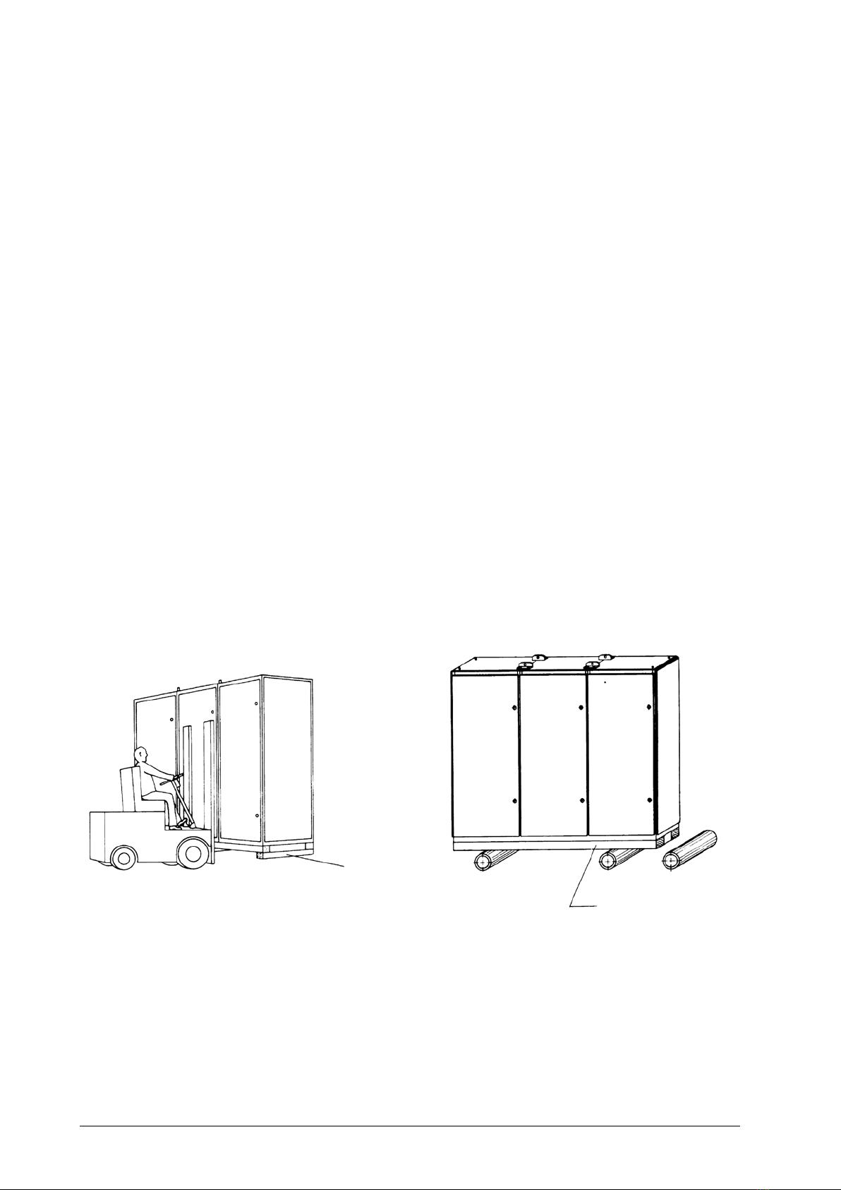
3.3 Delivery and Unloading Operations ...........................................................................10
3.3.1 Unloading................................................................................................................10
3.3.2 Transportation by Means of Crane............................................................................11
3.3.3 Storage ................................................................................................................... 12
3.3.4 Spare Module Storage ............................................................................................. 12
4. Installation and Start up ..................................................................................................... 13
4.1 Check on Delivery....................................................................................................13
4.2 Installation...............................................................................................................13
4.2.1 Erection and Connection of the Cubicles...................................................................13
4.2.2 Additional Information for Switchgear Positioning ......................................................14
4.2.3 Fastening Methods to Foundation.............................................................................15
4.3 Cable and Bar Connection ....................................................................................... 16
4.3.1 Protective Conductor Connection.............................................................................16
4.3.2 Protection Degree....................................................................................................17
4.4 Final Preparations .................................................................................................... 17
4.5 Check Operations....................................................................................................17
4.6 Start up...................................................................................................................18
5. Maintenance......................................................................................................................20
5.1 General ...................................................................................................................20
5.2 Maintenance Intervals .............................................................................................. 20
5.3 Maintenance Program..............................................................................................21
5.4 Repair Operations for Possible Malfunctions..............................................................23
5.5 Health and Safety .................................................................................................... 24
6. List of the Switchboard Main Equipment .............................................................................24
Appendix A: Bolts and nuts, and tightening torque
This document and the related enclosures, are property of ABB Sace S.p.A. It is forbidden to copy or
disclose them totally or partially, without ABB Sace S.p.A. approval.

6
1TTS900001M0902
1. Introduction
This document contains all necessary information for the installation, operation and maintenance of ABB
Sace MNS R low-voltage switchboards. Like all the switchboards produced by ABB Sace, also these
boards are designed for several system configurations. For this reason, our products can be subjected
to technical-constructive variations (Custom-made) according to the system requirements.
Therefore, it is necessary to refer to the most updated ABB Sace technical documentation, especially
in case of any possible variation.
Anyway, it is advisable that all the installation, start and service operations are carried out by qualified
personnel.
1.1 Consequences in case of non-compliance
ABB declines any responsibility in the following cases:
• Negligent handling of low-voltage switchboards and non-conformity with safety and operation rules.
• Insufficient maintenance, non-compliance with the procedures here described or inadequate repairs
carried out by unqualified personnel or with inadequate equipments.
• Any damage suffered during transportation.
• Inappropriate use.
• Modifications to low-voltage switchboards, which have not been carried out by authorized and qualified
personnel.

7
1TTS900001M0902
2. Switchboard
The Power Center MNS R switchboard consists of compartments equipped with open-air or moulded-
case circuit breakers, in fixed, plug-in, and withdrawable versions, auxiliary and measuring circuits,
together with main and distribution busbar systems.
2.1 Technical Data
Standards MNS R Low Voltage Switchgears,
type tested switchgear
assemblies (TTA)
CEI 17-13/1, CEI EN 60439-1,
IEC 60439-1
Test certificates ABB SACE and SINAL
Electrical data Rated Voltages Rated insulation voltage
Rated operating voltage
Rated frequency
Rated impulse withstand voltage
1000 V 3 AC 800 V DC
690 V 3 AC
60 Hz max
12 kV
Rated currents Busbars
Rated current
Rated peak withstand current
Rated short time withstand
current (1s)
Distribution bars
Rated current
Rated peak withstand current
Rated short time withstand
current (1s)
Up to 6300 A max
Up to 220 kA max
Up to 100 kA max
630 ÷4000 A
220 kA
100 kA
Mechanical data Dimensions Heght
Width
Depth
Basic module (height)
2200 mm
300, 400, 600, 800, 1000, 1200 mm
1025, 1200, 1400, 1600 mm
E = 25 mm DIN 43660
Surface protection Frame
Internal subdivision
Transvers section
Enclosures
Alu-zinc coated
UNI EN 10130 zinc coated
UNI ISO 4520 zinc coated
Paint RAL 7035
Degrees of
protection IEC 529
Open door
Closed door
IP 2X
IP 30 standard
Form 1 ÷4b
Internal subdivision Cubicle - cubicle
Busbar compartment –
cable compartment
Equipment compartment –
Busbar compartment
Standard installation
condition
Installation Ambient
Temperature
Relative moisture
Altitude max.
Pollution degree
Internal
-5 °C; + 40 °C
max 50% at 40 °C
≤2000 m
≤3
Extra options Paint Enclosure Colour on request
Busbar system Busbars Sheated, treated
Special request Ambient temperature > 40°C
Protection degree > IP30
Internal arc 75 kA, 0,5 s 726 V
On request
On request
IEC 61641

8
1TTS900001M0902
2.2 Switchboard Basic Structure
2.2.1 Typical Side Section
The basic structure of the frame (steel C-sections, 2 mm thick, with holes at 25 mm intervals), consists of:
• Equipment compartment
• Busbar compartment
• Cable compartment
BUSBAR
COMPARTMENT
EQUIPMENT
COMPARTMENT
CABLE
COMPARTMENT
The equipment compartment consists of:
• Main circuit breakers
• Auxiliary devices
• Terminal boards
The busbar compartment consists of:
• Main busbars
• Distribution bars
The cable compartment consists of:
• Input and output cables
• Auxiliary accessory (connectors, auxiliary terminal boards, etc.)

9
1TTS900001M0902
2.2.2 Busbars
The busbars are in a central position; they consists of a single system or a double system and they can
be installed to different levels. It is possible to create a busbar system in 3-pole or 4-pole version.
The busbars are classified according to their length, corresponding to the sizes of the switchboard
shipping units.
2.2.3 Distribution bars
The distribution bars are the connection between the busbars ant the outgoing units.
The busbars can be installed in a single section along the whole length of the compartment, or at an
appropriate level for particular executions.

10
1TTS900001M0902
3. Packing and Transportation
3.1 General
The MNS R switchboards are delivered either in single cubicles or in shipping units not exceeding 2
meters in lenght, taking also into consideration the type of equipment installed and the available space
for handling the switchgear at the erection site.
If no special instruction are given by the customer, the switchboards are delivered with standard pack-
aging, according to ABB internal instructions, and a suitable method of shipping is selected.
3.2 Packing
The cubicles are protected by suitable packaging during transport and possible intermediate storage.
3.3 Delivery and Unloading Operations
The unloading operation must be carried out by means of cranes or lift trucks. The load must be laid
down on a level surface.
3.3.1 Unloading
• By means of lift trucks (see Figure).
• By means of lifting and sliding devices (see Figure).
• If necessary, by means of rollers (min. 3 pieces). For roller transport, the wooden crossbeams must
be removed (only for cubicles with transverse sections up to 1200 kg) (see Figure).
• The compartments for switchboard must be transported only in vertical position.
• Tilting and canting must be avoided.
Crossbeam
Transport frame
(wooden beam 10 x 12 cm)

11
1TTS900001M0902
The transportation on manual lift
truck is dangerous, the apparatus
can overturn. For this reason, the
distance between the crossbeams
or pallets and the bottom must not
exceed 3 mm (see Figure).
3.3.2 Transportation by Means of Crane
• For the transportation by means of a crane, the compartments and the related sending units must be
equipped with lifting angles.
• It is not allowed to fix the lifting devices to the frame sections.
• The angle between the lifting cable and the crane hook must not exceed 120° (see Figure).
• The lifting angles can be removed after the apparatus installation has been performed.
• The fastening holes for the lifting angles are to be plugged with plugs GMN 775 502 P18 caps.

12
1TTS900001M0902
Approximate value for acceptable weights lifted by the cable
Cable diameter
mm
Acceptable load for a 4-cable device, angle between the cable and the crane
hook
Hemp cable
DlN 83325
Kg
Perlon cable
DlN 83330
Kg
Steel cable
DlN 15060 (160 kg/mm2)
Kg
8
10
12
14
16
18
20
24
30
36
-
180
280
350
470
580
720
1000
1600
2400
-
400
600
820
1060
1340
1660
2400
-
-
890
1440
2100
2900
-
-
-
-
-
-
For a 90° angle, the acceptable load is approximately 40% greater than the values shown in the table.
The sending units, with one or two compartments, are equipped with single eyebolts.
3.3.3 Storage
Storage kind and time depend on the packaging-type.
Standard packaging:
• After the arrival, the goods must be stored in rooms where no condensation can occur.
• Unpack immediately.
• Let the door opened for several hours, to acclimatize the equipment.
• Cover the panels with plastic sheeting in case of any further storage.
• Check for condensation before the installation.
Packaging for marine transportation/export (on request):
• Protection against moisture is only guaranteed if the packaging is undamaged.
• Intermediate outdoor storage is possible.
• 12-month storage is possible, if the goods is wrapped in heat sealed protective sheeting and the
packaging is undamaged.
• If the storage period is exceeded, the drying agent must be renewed and the plastic covering must
be sealed again.
3.3.4 Spare Module Storage
• In dry rooms.
• Modules must be stored in undamaged original packaging.
• Modules must not suffer sudden changes in temperature.
• Boxes must be stored with the upper side upward.

13
1TTS900001M0902
4. Installation and Start up
4.1 Check on Delivery
After the arrival check that goods is:
• Undamaged in each components.
• Free of damages (otherwise, determine damage entity, cause and possible responsible).
When the damage is detected, proceed as follows:
• Register the visible damage on the delivery note.
• Inform opportunely ABB Sace (directly or by means of the supplier or sales representative).
• For non-visible damages, inform, within a week, the forwarding agent by means of a written document.
Complaints for any damage or for other reasons, following the delivery of the goods, must indicate the
year of construction of the switchboard and the number of the order confirmation sent by ABB Sace,
which are written on the enclosed supply documents.
In case of loss of supply documents, or failure to make a claim, ABB Sace de-
clines any responsibility.
4.2 Installation
It is necessary to keep the best internal conditions, to guarantee an adequate illumination and free ac-
cess to switchboards. It is recommended to heat the room to avoid sudden changes in temperature,
high humidity and condensate.
For a correct installation of the switchboard, it is important to prearrange the frame with care. This must
be prepared in advance, with respect to the date of installation, according to the design document
indications.
4.2.1 Erection and Connection of the Cubicles
To install the compartments, proceed as follows:
1. Shipping units to be installed must be aligned with care. Check that they are in vertical position.
Doors and panels must not be twisted or stressed. Assembly can start from the right or left.
2. Shipping units frames can be screwed together (see Figure). Vertical sections are fixed on the left
front and right rear sides, by means of 4 special nuts.
For threaded rivet initial fixing, use an electric or pneumatic screwing device.

14
1TTS900001M0902
Threaded rivet
Splice bar
4.2.2 Additional Information for Switchgear Positioning
Minimum distance around the compartments, on the front and rear sides, must be at least 1200 mm
(see Figure).
To install the last compartment (right), the distance between the last compartment and the wall (right)
must be 150 mm.
In case of compartments, with doors installed on the left side, the minimum distance between the left
wall and the last left compartment must be 150 mm, so the doors can be opened in an angle of more
than 90°.
The distance between the upper edge of the highest cubicle end and the ceiling must be min. 500 mm
for cubicles which are internal arc proof (see Figure).

15
1TTS900001M0902
4.2.3 Fastening Methods to Foundation
The installation of switchboards equipped with cables entering form the bottom, requires a foundation
with an opening or a cable duct.
Compartments must be installed on a base frame which is:
• Embedded in the concrete floor
• Fixed on supports on a false floor.
To install the base frame, proceed as follows:
• The base frame should be aligned and checked by an ABB Sace qualified operator (on customer’s
request).
• The frame must not exceed a horizontal tolerance of ±1 mm on a length of 1 m.
• The frame must not ondulate.
2/1000
During the installation, the switchboard is welded or screwed to the base frame (see Figure).
• The welded joint length, on the front and rear sides of each cubicle, should not be less than 20 mm.
Each welding should be protected against corrosion by means of an adequate treating (a coat of paint).
• The screwed connection is carried out through the transverse section, using M10 screws. (see Figure).
If the switchboard is installed on false floors, proceed as follows:
• Tolerance is the same as in the case of a base frame.
• The subsoil must be solid, so that the tolerances are not exceeded by settling of the soil (especially
when using insulation layers and adhesives).
• The false floor must have a carrying capacity of p=20 kN/m2(compression load from the top to the
bottom).

16
1TTS900001M0902
4.3 Cable and Bar Connection
For any connections and, in particular for those made with standard elements, it is necessary to conform
to the tightening torque indicated by the table in Annexe A.
Circuit breakers and main switching devices are normally connected with cable or busbar. In case of
parallel connection:
1. Power and control cables must be fastened to cable mounting rails.
2. Power and control cables are connected to:
• Terminal boards
• Connection bars or
• Outgoing cable connection unit
The terminations of each circuit breaker installed in the switchboard are silver plated. Before the con-
nection, terminations must be cleaned with a cloth and solvent.
- Check that the connection contact surface is flat and clean.
- Remove burrs, dents and oxidation by means of a file or a rough cloth. In case of busbars with special
protecting treating, after using the above-mentioned tools, restore the protecting treating.
- Remove any grease with a cloth and solvent.
Busbars Connection
Before assembling, carefully clean the busbar contact area with a cloth soaked in solvent, and lightly
grease with vaseline.
- Verify the busbar correct alignment
- Match the coupling elements
- Lock the joints by means of the coupling elements, bolts and nuts on issue.
Busbars, protective and neutral busbars must be screwed up at transportation subdivisions (connecting
elements included). Busbars points of connection are accessible from the rear side. If the installation is
carried out correctly, the holes match. Drilling is not permissible, due to the resulting chips. Contact
surfaces do not need any particular treating. As for tightening torque related to busbar connection, see
Appendix A.
4.3.1 Protective Conductor Connection
All switchboard compartments are normally equipped with an earth busbar as a protection against any
short-circuit current.
The earth busbar is located in the rear side of the switchboard (at the bottom). The earthing busbar joint
of each shipping unit must be made according to the following procedures:
- Remove any traces of oxidation from the contact surfaces of the busbars, by means of a file or emery
cloth.
- Remove any grease with a cloth and solvent.
- Perform the earth busbar joints by means of screws, washers and nuts on issue.
- Cover the joints with grease.

17
1TTS900001M0902
Switchboard earthing must be performed by means of copper conductor whose cross-sectional area is
not inferior to that of the earth busbar.
The doors are earthed by means of yellow-green copper conductors (cross-sectional area 2.5 mm2). No
connexion is necessary, if no energized element is connected to the door (≤50 V AC or ≤120 V DC).
Anyway, the connections of the protective conductor screwed on the painted surfaces must be
fastened by means of lock washers.
4.3.2 Protection Degree
According with the required protection degree, it is necessary to take care to seal the compartments in
the place of installation.
• For protection degrees ≥IP X2 or ≥IP 5X splice bar flanges must be sealed, if they had not yet been
sealed. To seal the splice bar flanges, use an adhesive sealant tape of 15 x 2 mm (GSIN100021P0010)
and apply it after cleaning the internal part of the flanges. The tape must protrude 3 mm from the edge
of the internal part of the flanges.
• For protection degrees ≥IP X1 or ≥IP 4X it is necessary to put a gasket between the compartments
(compartment/compartment) in the shipping division.
4.4 Final Preparations
• Remove the safety devices for the transportation of the heavy components of the apparatus.
• Assemble the equipment, as circuit breakers, fuses, lamps, meters. The various components are
opportunely labelled. Follow the enclosed assembly instructions.
• Remove foreign materials, as tools, packaging material and residuals.
• Clean the insulating parts by means of an antistatic cloth. Do not use carbon tetrachloride, trichlorethylene
or hydrocarbon solvents.
• Close the doors.
4.5 Check Operations
• Check the busbar connection to the transportation units. Tightening torque, Annexe A.
• Check base frame fastening.
• Check that the required protection degree is achieved, especially concerning the bottom closing.
• General visual inspection: appearance, completeness, labels, foreign materials in the switchboard,
and dirt.
• Check that cables connection and wiring connection has been carried out completely and correctly.

18
1TTS900001M0902
4.6 Start up
Before starting the switchboard, perform the inspection detailed in the following table.
ITEM OPERATION Note
1. Compartment • Visuallyinspectinternaland
external parts for any possible
evident damage; remove any
foreign material (i.e. test tools left
after the assembly)
• Carefullycleantheinsulating
parts, remove any trace of damp
• Removedustordirtfromtheair-
intake grilles
2. Power circuit connections Check the tightening and the
continuity
3. Earth busbar and related connections Check the tightening and the
continuity
4. Insulation Measure the insulation resistance of
the auxiliary power circuits (phase-
phase and phase-earth) and of the
anticondensate heater.
The measured value must be at
least > 100 Mohm
• Theinsulationresistance
value is strongly influenced
by environmental conditions
• Theswitchboardmust
NOT be put in service if the
insulation resistance is too
low, for example inferior to
1 Mohm
• Iftheinsulationresistance
low value is due to
humidity, activate the
anticondensate heater
(after having performed the
inspections described in
step 8, and possibly taking
the thermostat to the higher
value); if necessary use also
provisional heaters
5. Circuit breakers • Beforeputtinginservice,carry
out all necessary operation
described in the instructions
related to each circuit breaker
• Checkthenecessarydevicesand
the accessories for the operation;
in case of key-locked circuit
breaker (open or closed), each
circuit breaker must be equipped
with only one key
• Putthecircuitbreakersintothe
service position
6. Protective release device Check the correct calibration
according to the selective
diagrams of the plant

19
1TTS900001M0902
7. Auxiliary circuits According to the diagram, check the
functionality and the operation logic
sequences of the auxiliary circuits
Before performing this
inspection, check the
calibration of each relay of the
switchboard
8. Anticondensate heater • Feedthecircuit
• Adjustthethermostattothe
higher temperature allowed
• Checkthattheheater
temperature raises
• Adjustthethermostatsothat
the temperature inside the
switchboard is always higher than
the outside ambient temperature
(approximately 35° C)
• In case of particular apparatus configuration, it is possible that the previous inspections must be
integrated with others suggested by the technician responsible for the apparatus.
• Check that the current transformer secondary winding is connected to the related protective and/or
measuring amperometric circuit, then remove any possible short-circuit connections.
• In case the voltage transformer secondary winding must be connected to switchboard external equipment,
check for the following conditions, to avoid overloads or short-circuits in the voltage transformers:
- Check that the total comsumption of the equipment is not superior to the transformer capacities.
- Check for incorrect connections (also provisional) in the measuring circuit or connections not in
accordance with the switchboard connection and other units (supply switchboard, subswitchboards,
control or operating desks, etc.).
- Check that only one phase of the voltage transformer secondary winding is earthed.
• At the end of the preliminary test, carry out the following operations:
- Open and isolate all the circuit breakers
- Remove any testing connections
Close all doors of the circuit breakers and measuring cells
Check for internal metal segregations (according to the design constructive shape) of the external
closing panels
- Check that the different mechanical and electrical interlocks (possibly deactivated to carry out start
test with switchboard not powered) have been restored.
• Feed the control circuit
• Close the circuit breakers (according to system requirements), and ensure that any related function
operates regularly
• Check the correct operation of the auxiliary instruments.
Respect the general safety rules

20
1TTS900001M0902
DUTY CONDITIONS MAINTENANCE INTERVALS
Normal Perform the operations described in
the program
At least once a year
Installation in dusty or polluted
environments
• Performtheoperationsdescribed
in the maintenance program
• Checktheoperationofeach
apparatus, referring to the related
instruction manuals
At least every 6 months
Circuit breaker tripping for short-circuit • Performthecircuitbreaker
general inspection (see the
related installation, operation and
maintenance instructions)
• Checktheconditionofthe
shorted power cables
• Checkthecircuitbreakerterminal
connection
• Performtheoperationsdescribed
in the maintenance program
Before putting back into
service
5. Maintenance
5.1 General
Before performing any maintenance operation in the switchboard or in the installed equipment it is
compulsory to:
- Power the compartment off (if possible), otherwise power off only the relevant section (power and
auxiliary circuits)
- Earth the unit involved for work on it.
Only in case of absolute necessity and for switchboards in partially or totally segregated execution, it is
possible to keep in service some parts of the compartment. In any case, do not remove any diaphragm
or panel which require the use of tools, before having checked that in the related compartment area the
voltage has been cut off.
Establish the earth connection.
5.2 Maintenance Intervals
Other manuals for MNS R
1
Table of contents
Languages:
Other ABB Industrial Equipment manuals
Popular Industrial Equipment manuals by other brands

pela tools
pela tools 50845 quick start guide

amiad
amiad TAF Series Installation, operation and maintenance instructions

Challenge
Challenge CMT 330 Installation and operator's manual

ATS
ATS Pressure Aging Vessel 4 instruction manual

GREISING
GREISING Clean Marker Brush V1 operating instructions

Maxcess
Maxcess Tidland Force5 Chuck Installation operation & maintenance