TechVision PEE1ENN2-W User manual


Table of Contents
1Product Overview ........................................................................................ 1
1.1 Intro to Product................................................................................................ 1
2Structure...................................................................................................... 2
2.1 Front Panel ..................................................................................................... 2
2.2 Rear Panel...................................................................................................... 3
3Networking Scene........................................................................................ 4
4Installation and Debug................................................................................. 5
4.1 Device Wiring.................................................................................................. 5
4.2 Device Installation........................................................................................... 5
4.2.1 Screw.................................................................................................... 6
4.2.2 Installation Step .................................................................................... 6
4.3 Debug Device ................................................................................................. 7
4.3.1 Before Debugging................................................................................. 7
4.3.2 Debug Device ....................................................................................... 8
4.3.3 Successfully Debug............................................................................. 11
5Web Config.................................................................................................. 1
5.1 WEB Login and Logout ................................................................................... 1
5.1.1 Login..................................................................................................... 1
5.1.2 Logout................................................................................................... 1
5.2 System Config................................................................................................. 2
5.2.1 Local Config.......................................................................................... 2
5.2.2 LAN Config ........................................................................................... 7
5.2.3 Indoor Manager..................................................................................... 8
5.2.4 Network Config ................................................................................... 10
5.2.5 Video Set............................................................................................ 12
5.2.6 User Manager..................................................................................... 14

5.2.7 IPC...................................................................................................... 16
5.2.8 WIFI Info............................................................................................. 17
5.3 Info Search.................................................................................................... 17
5.3.1 Call History ......................................................................................... 18
5.3.2 Alarm Record...................................................................................... 18
5.3.3 Unlock Record .................................................................................... 18
5.4 Status Statistics............................................................................................. 19
6Basic Function Introduction........................................................................ 20
6.1 Monitor.......................................................................................................... 20
6.2 Call Function................................................................................................. 20
6.3 Unlock........................................................................................................... 20
6.4 Restore Backup............................................................................................. 20
Appendix 1 Technical Specifications....................................................................... 21

Important Safeguards and Warnings
Please read the following safeguards and warnings carefully before using the product in
order to avoid damages and losses.
Note:
Do not expose the device to lampblack, steam or dust. Otherwise it may cause
fire or electric shock.
Do not install the device at position exposed to sunlight or in high temperature.
Temperature rise in device may cause fire.
Do not expose the device to humid environment. Otherwise it may cause fire.
The device must be installed on solid and flat surface in order to guarantee
safety under load and earthquake. Otherwise, it may cause device to fall off or
turnover.
Do not place the device on carpet or quilt.
Do not block air vent of the device or ventilation around the device. Otherwise,
temperature in device will rise and may cause fire.
Do not place any object on the device.
Do not disassemble the device without professional instruction.
Warning:
Please use battery properly to avoid fire, explosion and other dangers.
Please replace used battery with battery of the same type.
Do not use power line other than the one specified. Please use it properly.
Otherwise, it may cause fire or electric shock.
Special Announcement
This manual is for reference only.
All the designs and software here are subject to change without prior written
notice.
owners.
If there is any uncertainty or controversy, please refer to the final explanation of
us.

1
1 Product Overview
1.1 Intro to Product
Digital villa VTO has easy operation, simple installation and support:
WIFI
Mobile phone live preview
Call VTH, and perform video talk
Door unlock by card
One-click MGT center
Vandal-proof alarm and etc.

2
2 Structure
2.1 Front Panel
Device front panel is in Figure 2-1. Description of each component is in Chart 2-1.
Figure 2-1
No.
Port Name
Note
1
MIC
Audio input.
2
Camera
It monitors corresponding door region.
3
Card Area
Authorize IC card to unlock (card issuing),
swipe card to unlock.
4
Indicator
In standby status, blue light is NO.
Network offline, blue light flashes when
call VTH or MGT center.
5
Call
Button
Call MGT center or VTH.
6
Speaker
Audio output.
Chart 2-1
3
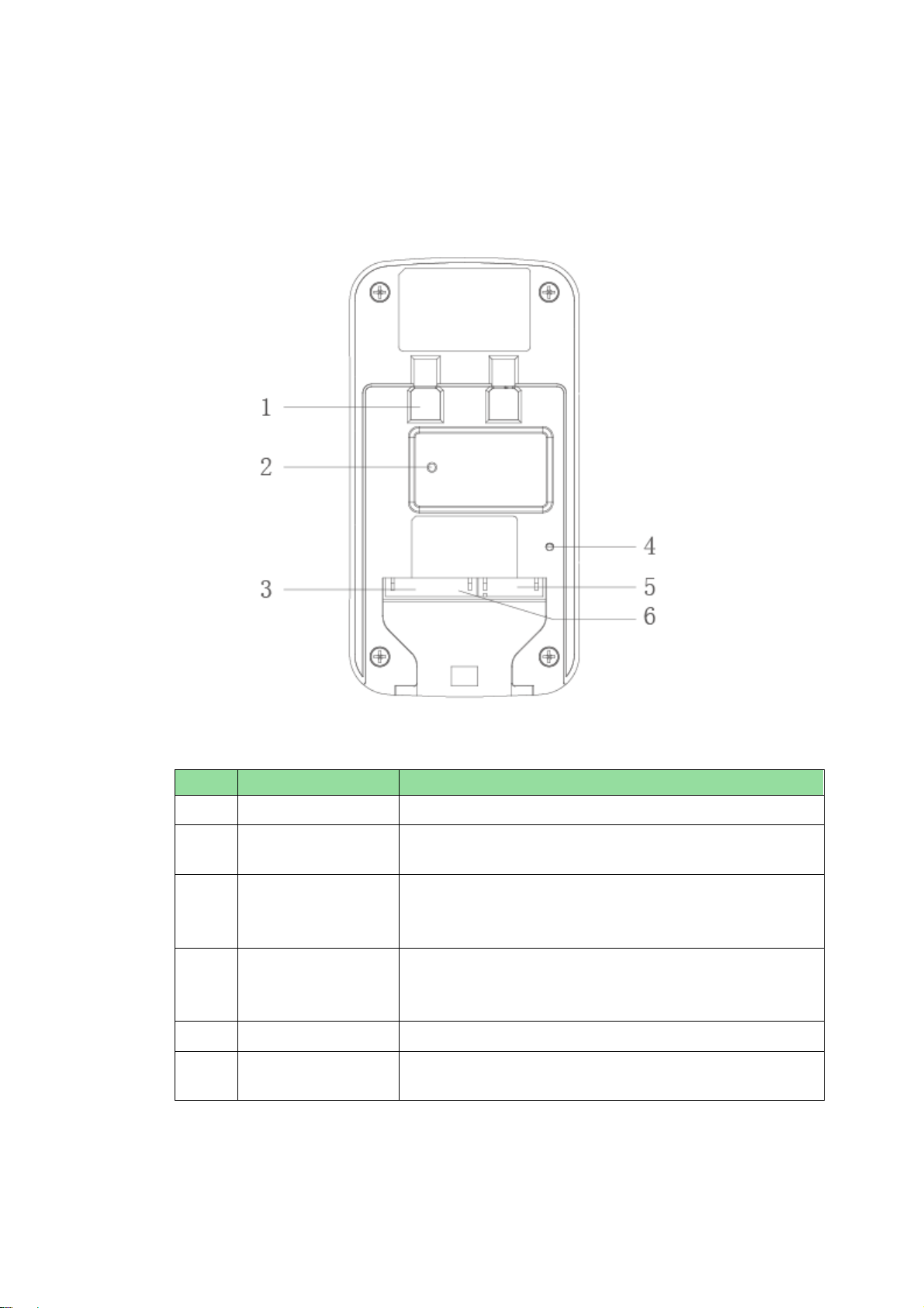
2.2 Rear Panel
Device rear panel is in Figure 2-2. Description of each component is in Chart 2-2.
Figure 2-2
Chart 2-2
No.
Component Name
Note
1
Bracket Position
Bracket used to fix device and wall.
2
Vandal-proof
Switch
When villa VTO is forced to leave wall, it will alarm and
send alarm to MGT center.
3
Alarm
Input/output
Interface
1-ch alarm input.
4
RESET Key
Shortly press this key to config reset WIFI.
Long press this key for 10s, system will restore
default settings.
5
RJ45 Interface
Standard Ethernet cable, support POE power.
6
Power Input
Interface
DC 12V input, support 9V-26V wide voltage, with
anti-reverse connection.


5
4 Installation and Debug
4.1 Device Wiring
Device wiring is in Figure 4-1.
Figure 4-1
4.2 Device Installation
Warning:
Avoid installation in poor environment, such as condensation, high temperature, oil
stain, dust, corrosion or direct sunlight.
Project installation and debugging must be done by professionals. Please do not
open the device in case of failure, and please contact after sales service.

6
4.2.1 Screw
For installation, please use screw according to Chart 4-1.
Component Name
Illustration
Quantity
M4×30 cross pan head
machine screw
2
Chart 4-1
4.2.2Installation Step
VTH installation is in Figure 4-2.
Figure 4-2
Steps:
Step 1. According to position of bracket, dig hole on installation surface (such as wall).
Step 2. Insert expansion bolt in hole you just dug.
Step 3. Fix bracket on designated position with screw.
Step 4. Fix device on bracket with screw.
Step 5. Install tail sealing element at device tail. Use two M4×30 screw pan head
machine screw to fix bracket on 86 box.

7
Note:
The recommended distance from device center to ground is 1.4m~1.6m.
4.3 Debug Device
4.3.1Before Debugging
Warning:
Debugging personnel shall be familiar with related materials, know device installation,
wiring and usage.
Debugging personnel check whether circuit has short circuit or open circuit or not.
Make sure circuit is normal, plug device to power.
After debugging end, clear up site (handle plugs, fix device and etc.)
Villa VTO default IP address is 192.168.1.110. Before you use the VTO, you must modify
its IP to be in the same network segment with the VTH.
Step to debug:
Step 1. Connect device to power, and power up.
Step 2. In PC browser, enter device default IP address 192.168.1.110. See Figure 4-3.
Figure 4-3
Step 3. Enter username and password.
Note:
Default username is “admin”. Default password is “admin”. Please refer to Ch 5.2.4.1
for setup.
8
After modification is finished, WEB page will restart and go to new IP address.
4.3.2Debug Device
Step 1. Plug device to power.
Step 2. In homepage, long press Settings for 6 seconds. Device pops up Password
Verification box.
Step 3. Enter project setup password which is 002236 by default.
Step 4. Press Net Set to connect VTH.
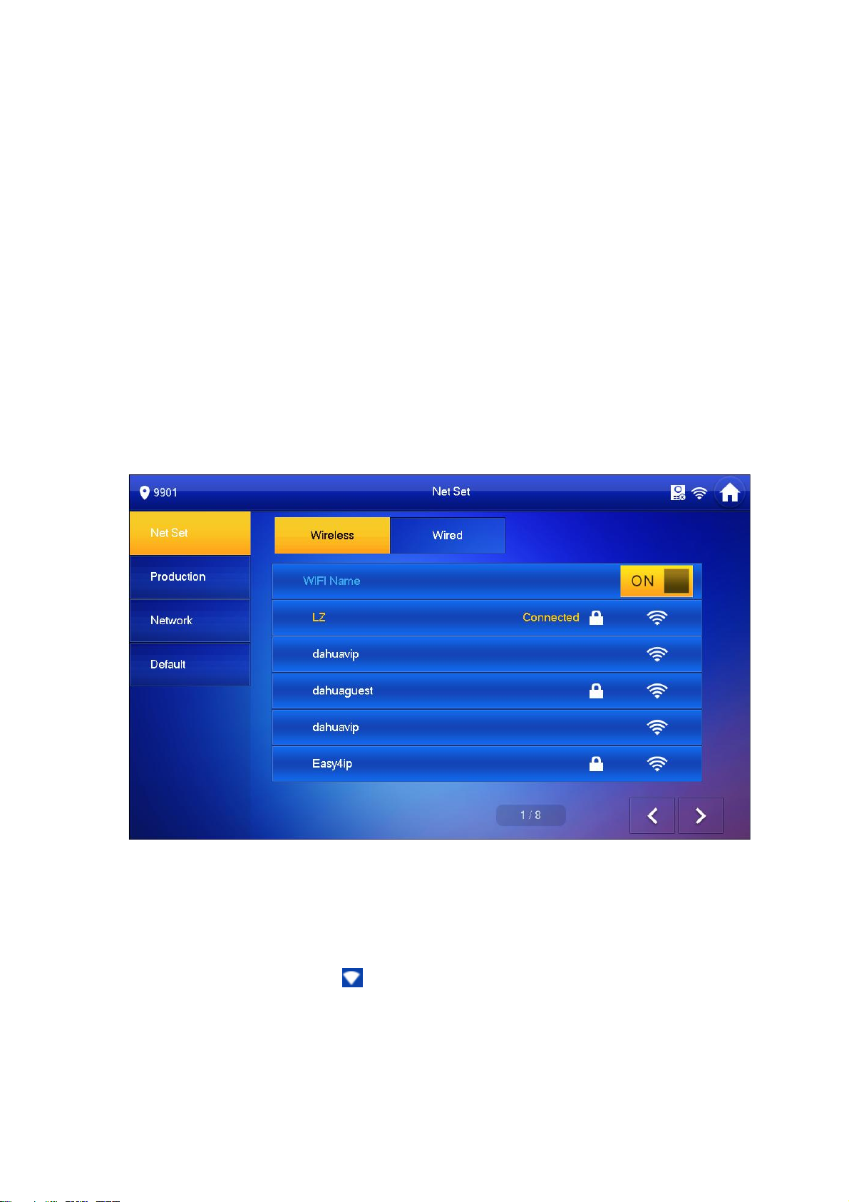
Wireless:
If the VTH supports WI-FI, you can select wireless connection.
1.Select Wireless, open WLAN, view available WI-FI. See Figure 4-4.
Figure 4-4
2.Select WI-FI you want to connect, and in pop-up WLAN connection window,
enter WI-FI password.
3.Press OK.
Now device interface shows at the upper-right corner which means wireless
connection is successful.
Wired:
1.Select Wired. See Figure 4-5.
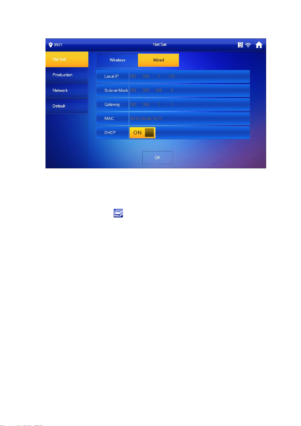
9
Figure 4-5
2.Enter VTH Local IP, Subnet Mask and Gateway.
3.Press OK.
Now device interface shows at the upper right corner which means wired connection
is successful.
Note:
You also can enable DHCP to auto gain VTH IP, subnet mask and gateway and press
OK to complete wired connection.
Step 5. Press Production to config VTH room no.
Warning:
VTH room no. must match VTH short no. on WEB of corresponding VTO. Please
refer to Ch 5.2.3.
If you want to set this VTH to be master VTH, then you shall select Master.
Fill in room no., press OK to save, see Figure 4-6.
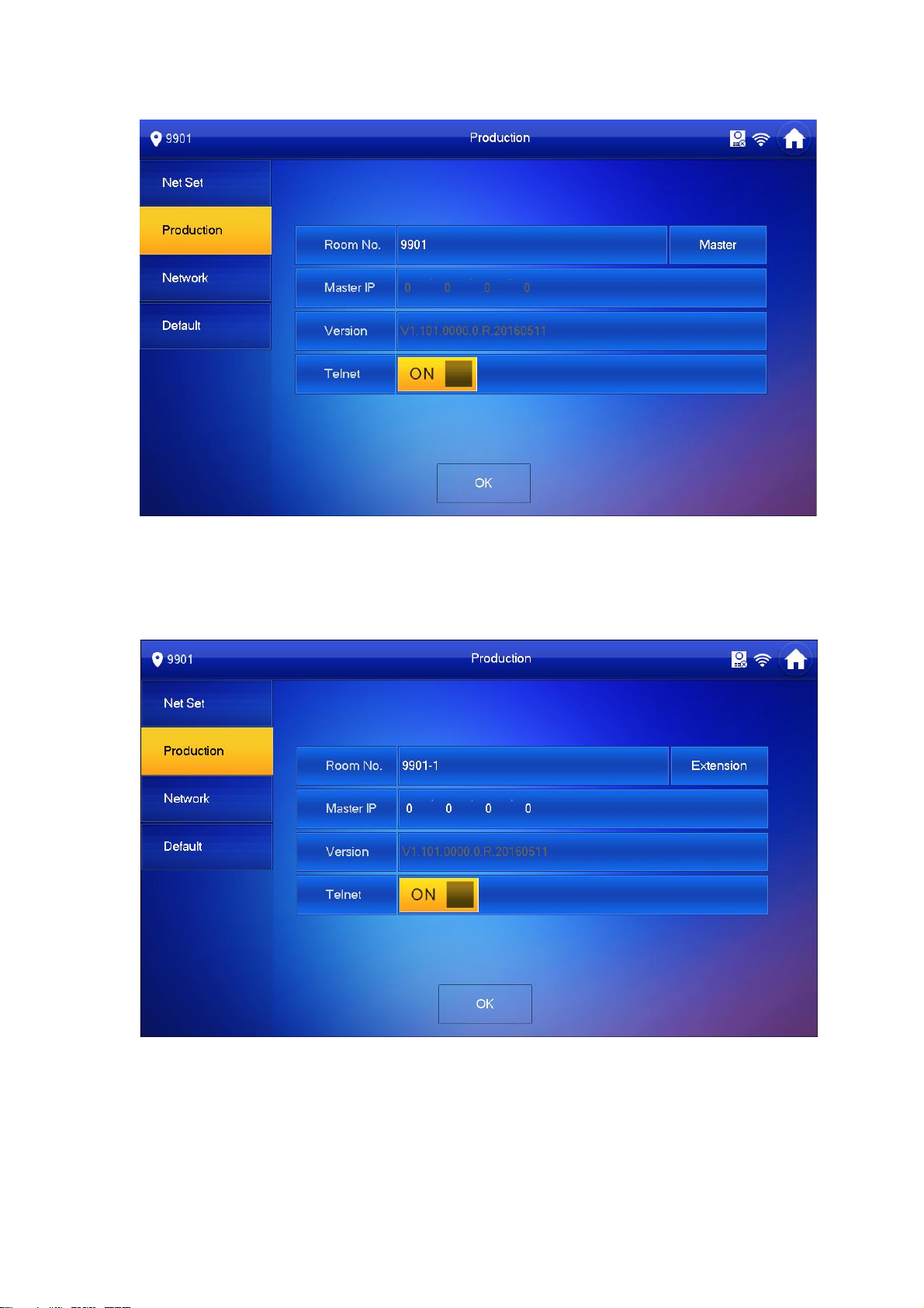
10
Figure 4-6
If you want to set this VTH to be extension VTH, then you shall select Extension.
Fill in user config info for extension to auto sync with master, such as room no.
and master IP. See Figure 4-7.
Figure 4-7
4.Press OK to save config.
System pops up prompt interface which means config is successful.
Note:

11
Telnet server is ON, debugging personnel can view VTH config via
telnet+IP.
Step 6. Press Network to config VTO info.
Warning:
Before config, please make sure VTO is plugged to power and is in the same segment
with VTH.
1. Fill in VTO name, master VTO IP address, set enable status to , see Figure
4-8.
Figure 4-8
2. Fill in VTO name, and extension VTO IP address, select device type, set enable
status to .
The device supports n19 units of extensions, and you can press to page down
to add more extensions.
4.3.3Successfully Debug
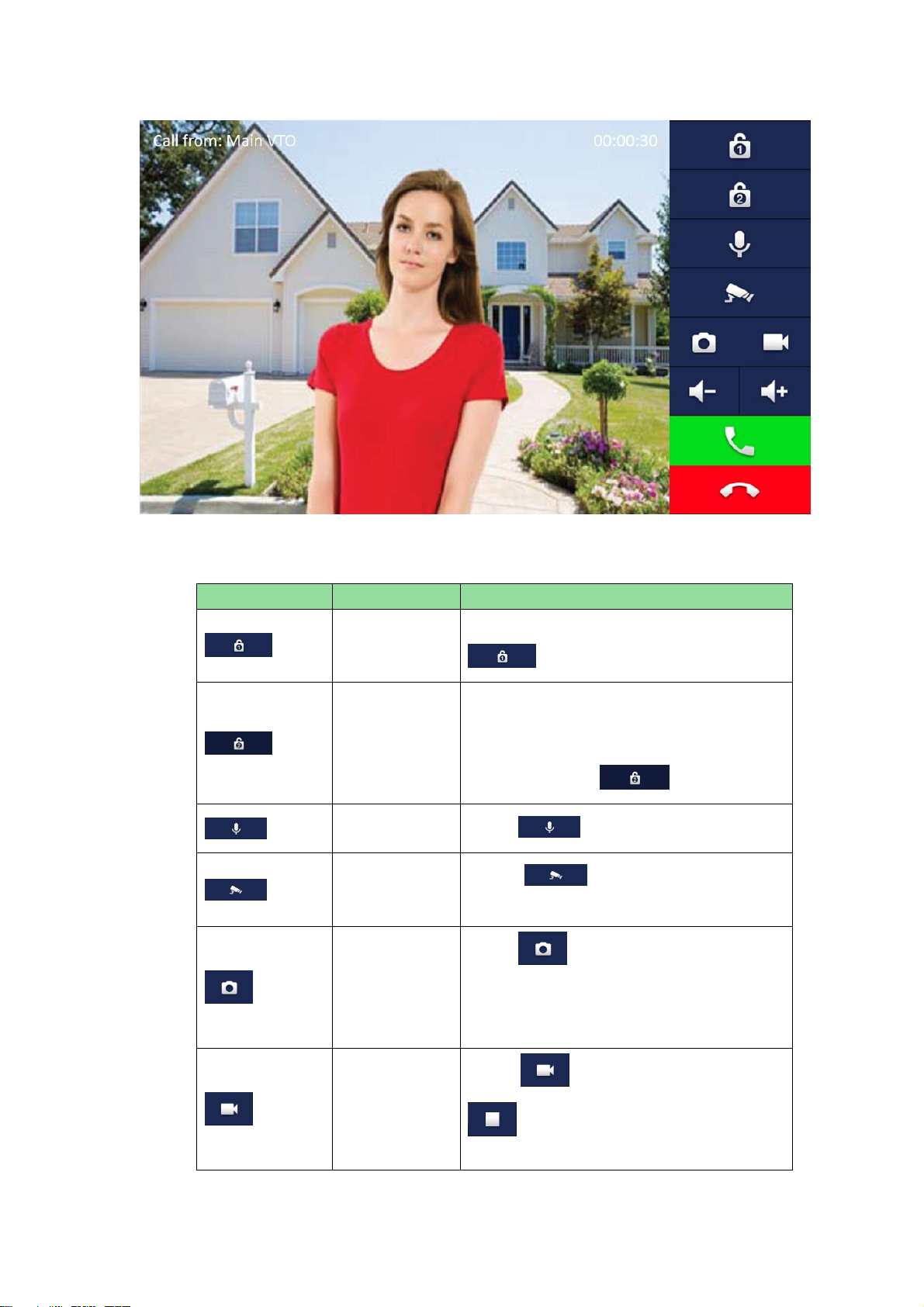
On VTO dial VTO room no. to call VTH. VTH pops up monitoring video and operation
buttons, see Figure 4-9.
12
Figure 4-9
Icon
Icon Name
Note
Unlock 1
VTO config electric control lock, press
, unlock.
Unlock 2
If this VTO has 485 expansion interface, it
can expand electric control lock or door
sensor lock, after successfully matching
with VTH, press , unlock.
MIC
Press , turn off MIC volume.
IP Camera
Press ,select IPC video of
monitoring favorites.
Snapshot
Press ,to snapshot.
Note:
When SD card is not installed, this button is
grey.
Record
Press ,record;call ends, press
end recording.
Records are stored to SD card of this VTH,

13
Icon
Icon Name
Note
if full, it overwrites from the earliest record.
Note:
When SD card is not installed, this button is
grey.
、
Volume
Adjust call volume.
Accept Call
-
Hang up
-

1
5 Web Config
This chapter introduces VTO WEB interface and its parameters, and how to configure
them.
5.1 WEB Login and Logout
5.1.1 Login
Step 1. In PC browser, enter device default IP address 192.168.1.110. See Figure 5-1.
Note:
Default username is “admin”. Default password is “admin”. Please refer to Ch
5.2.4.1 for setup.
Figure 5-1
Step 2. Enter username and password.
Note:
Default username is “admin. Default password is “admin”. After first time login,
please change password for security reasons. Please refer to Ch 5.2.6.3.
Step 3. Click Login.
5.1.2 Logout
Step 1. Select Logout>Logout>Logout. See Figure 5-2.

2
Figure 5-2
Step 2. Click Logout.
System exits WEB interface, return to login interface. You can go to Logout>Reboot
Device>Reboot Device interface, click Reboot Device to restart.
5.2 System Config
5.2.1 Local Config
In Local Config interface, you can view VTO model, version info and etc.
5.2.1.1 Local Config
In System Config>Local Config>Local Config interface, you can set light seneor, storage
point, reboot date and etc. See Figure 5-3 and Chart 5-1.
Figure 5-3
Parameter
Note
Sensor
Set compensation light threshold.
Storage Point
Storage path of record and picture, you can select FTP or SD card.

3
Please refer to Ch 5.2.4.2 for FTP setup.
Device Type
Display device type. Now it is “villa station”.
Reboot Date
On the set date, device will automatically reboot. Default is 2:00 a.m.
Tuesday.
Version Info
Display device version info.
Dial Rule
There are serial and non-serial.
Default
Only restore current Local Config page to default settings.
Refresh
Click Refresh to refresh current interface.
OK
Click OK to save.
Chart 5-1
5.2.1.2 A&C Manager
A&C Manager mainly controls unlock responding interval time, unlock period and door
sensor check time.
Go to System Config>Local Config>A&C Manager. See Figure 5-4 and Chart 5-2.
Figure 5-4
Parameter
Note
Unlock Responding
Interval
The interval between current unlock and next one,
unit is second.
Unlock Period
Period door remains unlocked, unit is second.
Door Sensor Check
Time
When only use door sensor, check”Check Door
Sensor Signal Before Lock”, Set “Door Sensor Check
Time” to enable it.
When door remains unlocked over set door sensor
check time, it alarms.
Check Door Sensor
Signal Before Lock
Auto Snapshot
Select Enable, when you swipe card, it auto snapshot
two pictures and upload them to FTP or SD card.
Upload Unlock Record
Select Enable, upload unlock record. You can view in
Info Search>Unlock Record> VTO Unlock Record.
Issue Card
Authorize IC card unlock right, convenient for user to
This manual suits for next models
1
Table of contents
Popular Accessories manuals by other brands

Tejovat Smart Home Products
Tejovat Smart Home Products TJ-SH-DP1500 user manual

Covidien
Covidien Nellcor MAXFAST Instructions for use

autosen
autosen AP008 operating instructions

SunnCamp
SunnCamp Strand 390 Plus instructions

HomeMatic
HomeMatic HmIP-DBB Mounting instruction and operating manual

Vmac
Vmac A700327 installation manual


