TecMate optimate TM470 User manual
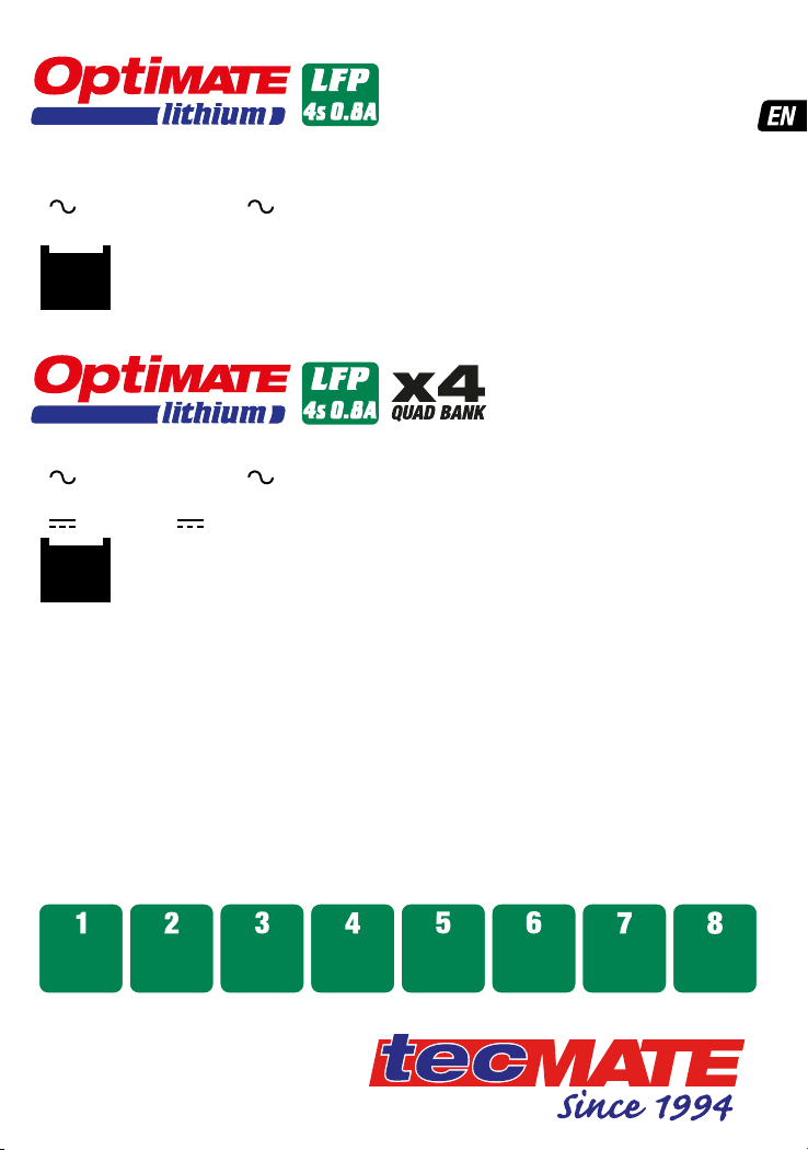
1 x 12.8V 4 series cell
Lithium Iron Phospate /
LFP 1 - 10Ah
+ -
MODEL: TM470 / TM471 / TM472 / TM478 /
TM497
AC: 100 – 240VAC 50-60Hz
0.23A @ 100Vac / 0.15A @ 240Vac
4 x 12.8V 4 series cell
Lithium Iron Phospate / LiFePO4 /
LFP 1 - 10Ah
+ -
MODEL: TM484 / TM485 / 486 / TM488
AC: 100 – 240VAC 50-60Hz
0.92A @ 100Vac / 0.60A @ 240Vac
DC: 12.8V 4 x 0.8A (independent)
Low Volt
Start
(0.5V)
SAVE -
monitor cells
TEST after
CHARGE
OptiMate ‘365’
Maintenance
Cell-balancing
CHARGE
TEST - cell
damage OPTIMIZE
LOW
VOLT SAVE
Automatic charger for 12.8V LiFePO4batteries
8 STEPS
INSTRUCTIONS FOR USE
IMPORTANT: Read completely
before charging
12.8V LiFePO4
1 2 3 4
24-724-7
BmsBms
BATTERY SAVING CHARGER
& MAINTAINER for
12.8V LiFePO4 BATTERIES
/oml4s0.8a
optimate1.com
/oml4s0.8a
TM470
OUTPUT:
INPUT:
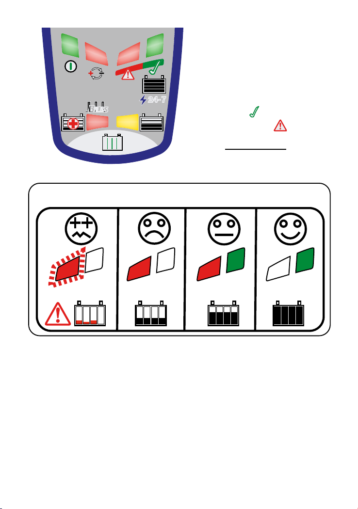
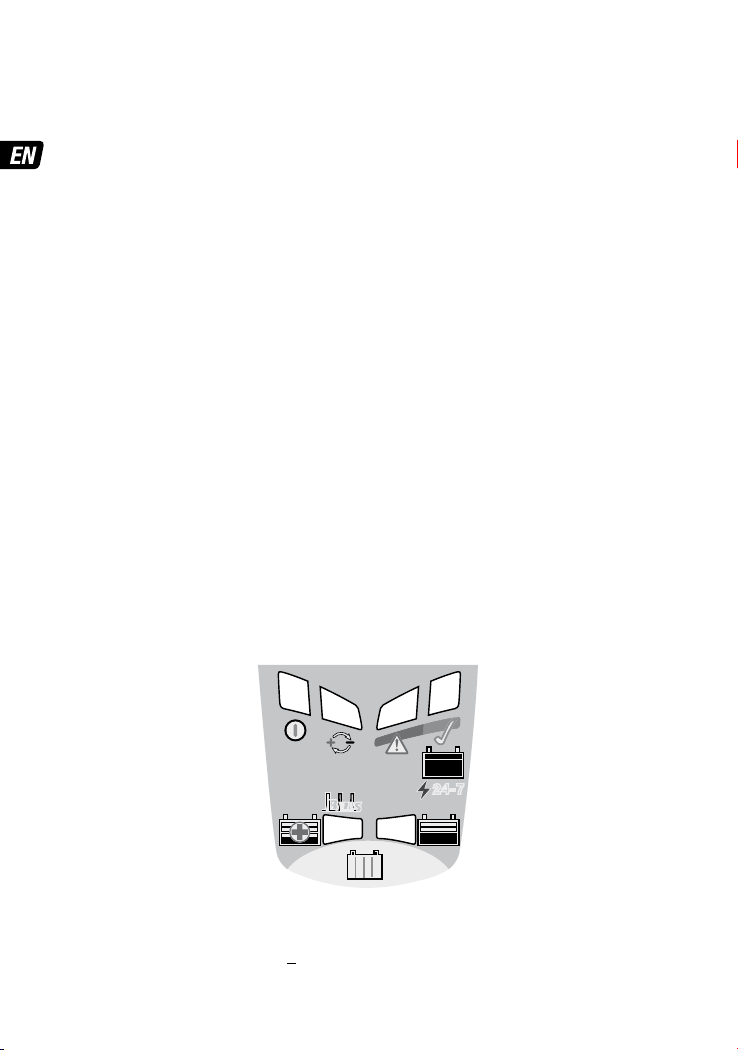
LED #1 AC POWER (100-240V)
LED #2 REVERSE POLARITY
LED #3 SAVE / SOC: 0 - 49%
LED #4 CHARGE / SOC: 50%+
LED #5 MAINTAIN / SOC: 70% - 100%
/ SOH:
LED #6 BATTERY SOH:
1 5
2
3 4
6
SOC - State Of Charge
SOH - State Of Health
0 - 49%
< 0% 50 - 69% 70% +
TEST / S.O.C. (LED #5 & LED #6)
Model: TM484 / TM485 / TM486 / TM488
Charge stations / banks on OptiMate Lithium 4s 0.8A x4 operate independently.

3
SAVE THESE INSTRUCTIONS. IT IS OF THE UTMOST IMPORTANCE THAT EACH TIME,
BEFORE USING THE BATTERY CHARGER, YOU COMPLETELY FAMILIARIZE YOURSELF
WITH THESE SAFETY INSTRUCTIONS.
AUTOMATIC BATTERY CHARGER FOR 12.8V LiFePO4BATTERIES. DO
NOT USE FOR NiCd, NiMH, LEAD-ACID or any other types of Li-Ion OR
NON-RECHARGEABLE BATTERIES.
1. GENERAL BATTERY CHARGER PRECAUTIONS.
CAUTION : DO NOT CONNECT TO GROUND. Do not expose charger to rain or snow. Use of an
attachment not recommended or sold by the battery charger manufacturer may result in a
risk of fire, electric shock, or injury to persons. To reduce risk of damage to electric plug and
cord/cable, pull by plug rather than cord/cable when disconnecting charger. Do not operate
charger with damaged cord or plug - If the cable is damaged, it is essential to have it replaced
without delay by the manufacturer, an authorised service agent or a qualified workshop, to
avoid danger. Do not operate charger if it has received a sharp blow, been dropped, or has
been otherwise damaged in any way; take it to a qualified Service Technician. Do not
disassemble charger; take it to a qualified serviceman when service or repair is required.
Incorrect reassembly may result in a risk of electric shock or fire. Before attempting any
maintenance or cleaning, to reduce risk of electric shock, unplug the charger from the AC
outlet and the battery. Clean only with slightly moist, not wet, cloth. Do not use solvents.
2. AC EXTENSION CORDS/CABLES.
An extension cord/cable should not be used unless absolutely necessary. Use of improper
extension cord could result in a risk of fire and electric shock. If extension cord must be used
make sure that : a) pins on plug of extension cord are the same number, size and shape as
those of plug on charger, b) the extension cord is properly wired and in good electrical
condition, and c) the conductor wire size is large enough for the AC ampere rating of the
charger as specified in the table below.
AC INPUT RATING IN AMPERES
Equal to or greater than But less than LENGTH OF
CORD, FEET (m) AWG SIZE OF CORD
2A 3A 25 (17.6)
50 (15.2)
100 (30.5)
18
18
14
3.WARNING - RISK OF EXPLOSIVE GASES.
a) Working in the vicinity of a battery is dangerous. For this reason it
is of utmost importance that you follow the instructions each time you
use the charger.
b) To reduce risk of battery explosion, follow these instructions and those published by the
battery manufacturer and manufacturer of any equipment you intend to use in vicinity of the
battery. Review cautionary marking on these products and on engine.
4. PERSONAL PRECAUTIONS: a) Someone should be within range of your voice OR close
IMPORTANT SAFETY
INSTRUCTIONS
IMPORTANT SAFETY INSTRUCTIONS

4
enough to come to your aid when you work near a lithium battery. b) Have plenty of fresh
water and soap nearby in case the battery has ruptured and leaking electrolyte contacts skin,
clothing or eyes. c) Wear complete eye protection and clothing protection. Avoid touching
eyes while working near battery. d) If leaking battery electrolyte contacts or enters eye, flood
eye with cold running water for at least 10 minutes and get medical attention immediately. If
leaking battery electrolyte contacts skin or clothing, wash immediately with soap & water. e)
NEVER smoke or allow a spark or flame in vicinity of battery or engine. f) Be extra cautious
to reduce risk of dropping a metal tool onto battery. It might spark or short-circuit the battery
or other electrical part that may cause explosion. g) Remove personal metal items such as
rings, bracelets, necklaces, and watches when working with any battery. A lithium battery
can produce a short-circuit current high enough to weld a ring or the like to metal, causing a
severe burn. h) NEVER charge a lithium battery in temperatures below -20°C / -4°F.
5. CHARGER LOCATION: a) Do not operate charger in a closed-in area or restrict ventilation in
any way. b) Locate charger as far away from battery as DC cables permit. c) Do not set a
battery on top of charger. IMPORTANT : Place charger on a hard flat surface or mount onto a
vertical surface. Do not place on plastic, leather or textile surface.
6. DC CONNECTION PRECAUTIONS: a) Connect and disconnect DC output clips only after
removing AC cord from electric outlet. Never allow clips to touch each other. b) Attach clips to
battery and chassis as indicated in 8(e), 8(f), and 9(a) through 9(d).
NOTE : This battery charger has an automatic safety feature that will
prevent it from operating if the battery has been inversely connected.
Remove AC cord from electrical outlet, disconnect the battery clips, then reconnect correctly
according to the instructions below.
7. PREPARING THE BATTERY: a) If the battery is new, before connecting the charger read the
battery manufacturer’s safety and operational instructions carefully. b) If it is necessary to
remove battery from vehicle to charge, make sure all accessories in the vehicle are off, so as
not to cause an arc. First remove grounded terminal (normally marked NEGATIVE (NEG, N,–)
from battery first, then the terminal marked POSITIVE (POS, P, +).
c) Place the battery in a well ventilated area.
d) Visually check the battery for mechanical defects such as a bulging or cracked casing, or
signs of electrolyte leakage.If mechanical defects are apparent do not attempt to charge the
battery, have the battery professionally assessed.
e) Clean battery terminals. Be careful to keep corrosion from coming in contact with eyes. f)
Carefully follow manufacturer’s recharging instructions. h) Study all battery manufacturer’s
specific precautions such as recommended rates of charge. i) Determine voltage of battery by
referring to vehicle or other user’s manual and before making the battery connections, make
sure that the voltage of the battery you are going to charge matches the output voltage of the
battery charger.
8. FOLLOW THESE STEPS WHEN BATTERY IS INSTALLED IN VEHICLE
AND YOU CHOOSE TO USE BATTERY CLIPS TO CHARGE THE BATTERY.
SHORT CIRCUITING THE BATTERY MAY CAUSE AN EXPLOSION. TO
REDUCE RISK:a) Position AC and DC cords so as to reduce risk of damage by the vehicle
itself or moving engine parts. b) Stay clear of fan blades, belts, chains, sprockets, pulleys,
and other vehicle parts that can cause injury to persons or damage to the charger and its
cords/cables.
c) Check polarity of battery posts. On automotive batteries POSITIVE (POS, P, +) battery post
IMPORTANT SAFETY INSTRUCTIONS

5
usually has larger diameter than NEGATIVE (NEG, N,–) post.
d) Determine which post of battery is grounded (connected) to the chassis.
If negative post is grounded to chassis (as in most modern vehicles), see (e). If positive post
is grounded to the chassis, see (f).
e) For negative-grounded vehicle, connect POSITIVE (RED) clip from battery charger to
POSITIVE (POS, P, + ) ungrounded post of battery. Connect NEGATIVE (BLACK) clip to vehicle
chassis or engine block away from battery. Do not connect clip to carburetor, fuel lines, or
sheet-metal body parts. Connect to a heavy gage metal part of the frame or engine block.
f) For positive-grounded vehicle, connect NEGATIVE (BLACK) clip from battery charger to
NEGATIVE (NEG. N , -) ungrounded post of battery. Connect POSITIVE (RED) clip to vehicle
chassis or engine block away from battery. Do not connect clip to carburettor, fuel lines, or
sheet-metal body parts. Connect to a heavy gage metal part of the frame or engine block. g)
When disconnecting charger, turn switches to off, disconnect AC cord, remove clip from
vehicle chassis, and then remove clip from battery terminal. h) See operating instructions for
length of charge information.
9. FOLLOW THESE STEPS WHEN BATTERY IS OUTSIDE OF THE
VEHICLE OR HAS BEEN REMOVED FROM THE VEHICLE. SHORT
CIRCUITING THE BATTERY MAY CAUSE AN EXPLOSION. TO REDUCE
RISK: a) Check polarity of battery posts. The POSITIVE (POS, P, + ) and NEGATIVE (NEG,N,
- ) battery posts will be clearly marked. b) Connect the POSITIVE (RED) charger clip to
POSITIVE (POS, P, +) post of battery. c) Then connect the NEGATIVE (BLACK) charger clip to
the NEGATIVE (NEG, N, -) post of the battery. d) When disconnecting charger, always do so in
reverse sequence of connecting procedure & break first connection while as far away from
battery as practical.
10. SAFE USE BY MINORS OR PERSONS WITH REDUCED CAPABILITIES: a) This appliance can
be used by children aged from 8 years and above and persons with reduced physical, sensory
or mental capabilities or lack of experience and knowledge only if they have been given
supervision or instruction concerning use of the appliance in a safe way and understand the
hazards involved. Children shall not play with the appliance. Cleaning and user maintenance
shall not be made by children without supervision.
b) Choking Hazard. Accessories may present a choking hazard to children. Do not leave
children unattended with product or any accessory. The product is not a toy.
11. RADIO FREQUENCY INTERFERENCE: The OptiMate Lithium complies with Part 15 of
the FCC Rules. Operation is subject to the following two conditions: (1) this device may
not cause harmful interference, and (2) this device must accept any interference received,
including interference that may cause undesired operation. NOTE: This equipment has been
tested and found to comply with the limits for a Class A digital device, pursuant to Part
15 of the FCC Rules. These limits are designed to provide reasonable protection against
harmful interference when the equipment is operated in a commercial environment. This
equipment generates, uses, and can radiate radio frequency energy and, if not installed and
used in accordance with the instruction manual, may cause harmful interference to radio
communications.
12. PROPOSITION 65, STATE OF CALIFORNIA: Battery posts / terminals, and related
accessories may contain chemicals, including lead or sulphuric acid. These materials are
known to the State of California to cause cancer and birth defects and other reproductive
harm.
IMPORTANT SAFETY INSTRUCTIONS
6
USING THE OPTIMATE LITHIUM:
CONNECTION ACCESSORIES
Two interchangeable connection sets are supplied with the battery charger:
1) A battery lead with metal eyelet lugs for permanent fitment to the battery posts, and
re-sealable weatherproof cap on the on the connector that connects to the charger output
cable. Consult a professional service agent for assistance in attaching the metal eyelets to
the battery posts. Secure the connector with weatherproof cap so that it cannot foul any
moving part of the vehicle or the cable can be pinched or damaged by sharp edges.
IMPORTANT: This battery lead is protected by a 15A fuse. If under any circumstance the fuse
blows, do not try and replace the fuse without first identifying and correcting the issue that
caused the fuse to blow. Only replace the fuse with a 15A rated ATO fuse.
2) A set of battery clips for charging the battery on or off-vehicle. Read IMPORTANT SAFETY
INSTRUCTIONS points 8 or 9 before connecting to the battery.
OPTIONAL BATTERY CONNECTION: On some vehicles it is possible to charge the battery
through the fitted auxiliary 12V DIN/ISO 4165 power socket. The battery can only be charged
and maintained if the 12V socket remains powered up after the ignition has been turned off
and the vehicle has been parked. Find a suitable accessory at www.optimate1.com.
CHARGING TIME
Charge time on a flat but otherwise undamaged battery:
For batteries rated from 2.5Ah to 5Ah: 180 to 360 minutes to progress to the voltage
retention test.
For batteries rated above 5Ah: 125% of the battery’s Ah rating, so a 10Ah battery should
take no more than about 12.5 hours to progress to the voltage retention test.
Deep-discharged batteries may take significantly longer. A full charge may not be achieved
within the 24 hour charge safety limit. In this case follow the reset procedure below.
PROCEEDING TO CHARGE
The LED indicators below are sequenced as they may come on through the course of the program.
NOTE: Charge stations / banks on OptiMate Lithium 4s0.8A x4 operate independently.
LED #1 : POWER ON -Confirms AC power supply to the charger.
HIGH and LOW intensity indication: LOW: No battery connected. HIGH: battery connected and
current is being delivered.
12.8V LiFePO4
1 2 3 4
24-724-7
BmsBms
1 5
2
3 4
6

7
LED #2 : REVERSE POLARITY PROTECTION - Lights when the battery connections are
incorrect. The charger is electronically protected so no damage will result, and the output will
remain disabled until the connections are corrected.
BMS RESET PROCEDURE: For a multi-bank / station TM-484 / TM-485, BMS pulses are
automatically & continuously delivered if no battery voltage is sensed. After connection to the
battery the BMS has successfully reset when either LED #3 OR LED #4 lights by itself.
For a single bank / station TM-47x, TM-497 charger, follow this procedure: 1) Disconnect
OptiMate Lithium from mains supply. Wait for LED #1 to go out. 2) Connect OptiMate Lithium
to the battery: RED clamp to POSITIVE (POS, P or +) terminal and BLACK clamp to NEGATIVE
(NEG, N or –) terminal. 3) Reconnect the OptiMate Lithium to mains supply.
A special BMS reset pulse is delivered for a period of one minute. LED #3 flashes as each
reset pulse is delivered.
The BMS has successfully reset when either LED #3 OR LED #4 lights by itself.
BMS not resetting: 1) An advanced battery management system that includes thermal
protection, prevents operation if the battery temperature falls outside of the manufacturer
recommended safe operating temperature range. Check battery manufacturer's
specifications. 2) Battery is connected in reverse polarity. Correct the connections and try
again. 3) The vehicle or equipment circuit connected to the battery is preventing the pulse
from being delivered. Disconnect or turn off the circuit and try again. 4) The battery's BMS
may have suffered damage. Have the battery professionally assessed.
LED #3 SAVE : This mode engages if the battery was more than 90% discharged / voltage is
below 12.8V. During the SAVE mode the program limits charge current and tests for cell
damage. Charge current is automatically adjusted as charging progresses.
A healthy LiFePO4
battery will progress to CHARGE mode within 4 hours.
ERROR: TEST LED #6 flashing - Charging has been suspended as OptiMate has detected the
battery may have suffered permanent damage and a professional assessment is required.
CAUTION: A deep discharged LiFePO4battery may have developed permanent damage
in one or more cells. Higher capacity batteries with multiple cells in parallel (4s2p or more
configeration) may have a good cell paired with bad cell, if so, it will take longer to detect the
bad cell. Such a battery may heat up excessively during charging, confirming there is
a problem within the battery. ALWAYS monitor the battery temperature during the first
hour, then hourly there-after. If at any time the battery is uncomfortably hot to touch or
you notice any unusual signs, DISCONNECT THE CHARGER IMMEDIATELY.
CHARGE LED #4 - CHARGE, PULSE ABSORPTION & CHARGE VERIFICATION steps: A constant
current of 0.8 Amps is delivered into the battery, up to a voltage of 14.3V. Battery charge
level is verified. If the battery requires further charging variable current pulses are delivered
to the battery, bringing each cell to equal and full charge.
NOTE: For safety reasons there is an overall charge time limit of 48 hours.
LED #5: BATTERY READY / 24-7 Maintenance:
The battery can be used. If left connected (recommended), battery health is confirmed,
followed by the OptiMate 24-7 maintenance that maintains the battery at full charge.
5.1 Health test starts immediately after LED #5 lights.
Delivery of current to the battery is
interrupted for up to
12
**
hours
to allow the battery to settle and confirm that the vehicle
circuitry is not depleting the battery.
See page 2 for LED 5 & 6 corresponding to charge level /

battery health. LED #6 lights if battery is being depleted or health is not optimal.
** If charge delivery was less than 12h up to when LED #5 turned on, health test
extends until 24h has elapsed, followed by 24-7 maintenance.
5.2 OptiMate 24-7 maintenance: During every hour that the battery remains connected
OptiMate's 24-7 maintenance program delivers up to 30 minutes of float charge
maintenance at a voltage of 13.6V, followed and alternating wih 30 minute REST (no
charging) periods. Charge level is continuously monitored. OptiMate Lithium will counter
discharge by connected circuitry or battery self-discharge. TIP: At least once every two
weeks, check battery status. IMPORTANT: When handling batteries or in their vicinity,
always take care to observe the SAFETY WARNINGS above.
6. LED #6 flashing / blinking - BATTERY is not holding charge / charging suspended.
The battery’s voltage is not being sustained above 12V or could not be sufficiently recovered.
In the case of a battery still connected to the electrical system it supports, the red LED #6
may be signalling a loss of current through connected wiring or 'always on' current-
consuming accessories. A sudden load such as vehicle headlights being switched on or
engine started while the charger is connected can also cause the battery voltage to dip
significantly. To rectify: disconnect OptiMate Lithium, allow program to reset and then
reconnect.
ECO POWER SAVING MODE WHEN THE CHARGER IS CONNECTED TO AC SUPPLY:
The power converter switches to ECO mode when the charger is not connected to a battery
resulting in a very low power draw of less than 0.5W (per charging bank), equivalent to power
consumption of 0.012 kWh per day. When a battery is connected to the charger power
consumption depends on the current demand of the battery and its connected vehicle /
electronic circuitry. After the battery has been charged and the charger is in long term
maintenance charge mode (to keep the battery at 100% charge) the total power consumption
is estimated to be 0.024 kWh or less per day.
Learn more about battery chargers and jump starters we have.
Other manuals for optimate TM470
2
This manual suits for next models
8
Table of contents
Other TecMate Automobile Batteries Charger manuals


