Tecnik TRONIK 812 User manual

USER MANUAL
CF-MTL-2401/6003/42401/42403
www.tecnikchargers.comwww.tecnikchargers.comwww.tecnikchargers.com
T812-UM-201709-ENT812-UM-201709-ENT812-UM-201709-EN
TRONIKTRONIKTRONIK
812812812
www.tecnikchargers.comwww.tecnikchargers.comwww.tecnikchargers.com 222
INDEX
General
Shock prevention
Burn and injury prevention
Fire and explosion prevention
Arcing and burning of the connector
Medical and rst aid treatment
A.C. input wiring connection
A.C. input conguration (multi-input chargers only)
A.C. input calibration
3INTRODUCTION
CHARGER DESCRIPTION 6
CHARGER INSTALLATION 7-8
SAFETY INSTRUCTIONS AND WARNINGS 4-5
Programming the gassing point
Connecting the battery and autostart
Charge operation
Safety timer - Emergency stop
Automatic data saving
Blown D.C. fuse detection
Automatic charge termination
Automatic shutdown on battery disconnection
Manual charge termination
Manual equalize
Daily equalize
Automatic equalize and refresh
Refresh operation
USING THE CHARGER 9-15

www.tecnikchargers.comwww.tecnikchargers.comwww.tecnikchargers.com 333
INTRODUCTION
Before using your TRONIK battery charger, please take the time to read these instructions carefully. The owner’s manual is
an important part of the charger. It’s recommended to keep it in good condition for the lifetime of the charger. It should be
kept in a dry and clean place, always available to the users.
To indicate important instructions, the following colored blocks are used throughout this manual.
DANGER! This operation can be dangerous for the user
ATTENTION! This operation is important for the functionality and reliability of the charger

www.tecnikchargers.comwww.tecnikchargers.comwww.tecnikchargers.com 444
SAFETY INSTRUCTIONS AND WARNINGS
Battery chargers like the TRONIK can cause serious injury or death, or damage to other equipment or property, if the
operator does not strictly observe all safety rules and take precautionary actions. Safe practices must be learned through
study and training before using this equipment. Only qualied personnel should install, use, or service this equipment.
Bare conductors, or terminals in the output circuit, or ungrounded, electrically-live equipments can fatally shock a person. To
protect against shock, have competent electrician verify that the equipment is adequately grounded and learn what
terminals and parts are electrically HOT.
The body’s electrical resistance is decreased when wet, permitting dangerous current to ow through the body. Do not work
in damp area without being extremely careful. Stand on dry rubber mat or dry wood and use insulating gloves when
dampness or sweat cannot be avoided. Keep clothing dry.
INSTALLATION AND GROUNDING: A power disconnect switch must be located at the equipment. Check the data label for
voltage and phase requirements. If only 3-phase power is available, connect single-phase equipment to ONLY TWO WIRES
of the 3-phase line. DO NOT CONNECT the equipment grounding conductor to the third live wire of the 3-phase line as this
makes the equipment frame electrically HOT, which can cause a fatal shock. If a grounding conductor is part of the power
supply cable, be sure to connect it to a properly grounded switch box or building ground. If not part of the supply cable, use a
separate grounding conductor. Don’t remove a ground prong from any plug. Use correct mating receptacles. Check ground
for electrical continuity before using equipment. The grounding conductor must be of a size equal to or larger than the size of
the line conductors.
CHARGING LEADS: Inspect leads often for damage to the insulation. Replace or repair cracked or worn leads immediately.
Use leads having sufcient capacity to carry the operating current without overheating.
BATTERY TERMINALS: Do not touch battery terminals while equipment is operating.
SERVICE AND MAINTENANCE: 1) Shut OFF all power at the disconnect switch or line breaker BEFORE inspecting, adjusting,
or servicing the equipment. Lock switch OPEN (or remove line fuses) so that the power cannot be turned ON accidentally. 2)
Disconnect power to equipment if it is to be left unattended or out of service. 3) Disconnect battery from charger. 4) Keep
inside parts clean and dry. Dirt and/or moisture can cause insulation failure. This failure can result in high voltage at the
charger output.
GENERAL
SHOCK PREVENTION
The battery produces very high currents when short circuited, and will burn the skin severely if in contact with any metal
conductor that is carrying this current. Do not wear any jewelry that could come in contact with battery terminals or the cell
connectors on top of the battery.
Battery acid is very corrosive. Always wear correct eye and body protection when near batteries.
BURN AND INJURY PREVENTION

www.tecnikchargers.comwww.tecnikchargers.comwww.tecnikchargers.com 555
When batteries are being recharged, they generate hydrogen gas that is explosive in certain concentrations in air (the
ammability or explosive limits are 4.1% to 72% hydrogen in air). The spark-retarding vents help slow the rate of release of
hydrogen, but the escaping hydrogen may form an explosive atmosphere around the battery if ventilation is poor.
The ventilation system should be designed to provide an adequate amount of fresh air for the number of batteries being
charged. This is essential to prevent an explosion. Always keep sparks, ames, burning cigarettes, and other sources of
ignition away from the battery recharging area. Do not break "live" circuits at the terminals of batteries. Do not lay
tools or anything that is metallic on top of any battery.
FIRE AND EXPLOSION PREVENTION
To prevent arcing and burning of the connector contacts, be sure the charger is OFF before connecting or disconnecting the
battery. The ammeter should NOT indicate current ow.
ARCING AND BURNING OF CONNECTOR
First aid facilities and qualied rst aid personnel should be available for each shift for immediate treatment of electrical
shock victims.
EMERGENCY FIRST AID: Call a physician and ambulance immediately and use rst aid techniques recommended by the
American Red Cross.
MEDICAL AND FIRST AID TREATMENT
DANGER: ELECTRICAL SHOCK CAN BE FATAL
If person is unconscious and electric shock is suspected, do not touch person if he or she is in contact with charging
equipment, battery, charging leads, or other live electrical parts. Disconnect power at wall switch and then use First
Aid. Dry wood, wooden broom, and other insulating material can be used to move cables, if necessary, away from
person.
IF BREATHING IS DIFFICULT, give oxygen.
IF NOT BREATHING, BEGIN ARTIFICIAL BREATHING, such as mouth-to-mouth.
IF PULSE IS ABSENT, BEGIN ARTIFICIAL CIRCULATION, such as external heart massage.
In case of acid in the eyes, ush very well with clean water and seek professional medical attention immediately.
SAFETY INSTRUCTIONS AND WARNINGS
www.tecnikchargers.comwww.tecnikchargers.comwww.tecnikchargers.com 666
CHARGER DESCRIPTION
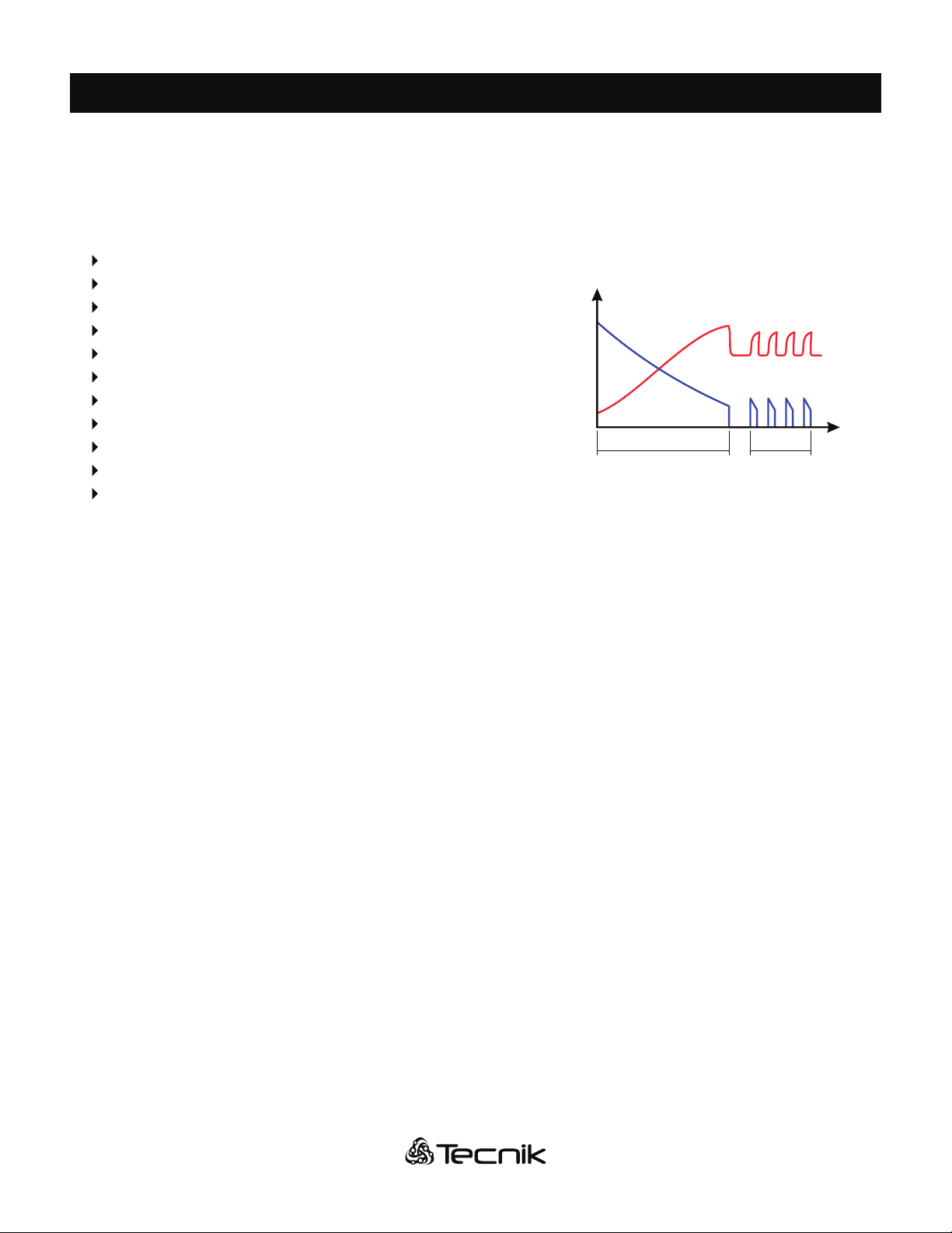
TRONIK chargers have been designed to charge lead-acid batteries. These units convert the A.C. input to a D.C. output at
the correct voltage with a Wa type charge curve.
TRONIK charger operation is managed by the MTL digital charge controller, which is a microprocessor based electronic
board of the last generation. Important features of the controller are:
Gassing point (80%) programming by DIP switches
Proportional Algorithm for charge time calculation
Programmable Equalize System (Automatic Pulsed & Manual)
Automatic voltage-controlled maintenance
Wrong battery detection
Battery desulphation cycle
Independent safety timer
Automatic data-saving in case of A.C. input black out
Cyclical indication of V/cell, AMPS, Ah returned, time
Cool down time counter
Scrolling messages in plain text
The MTL charge controller monitors the entire charging curve, and it incorporates several safety features.
The front panel contains the digital display (4-Digits), the STOP button and the MANUAL-EQUALIZE button.
Charge cycle Equalizing
Time
Voltage (V)
Current (A)
www.tecnikchargers.comwww.tecnikchargers.comwww.tecnikchargers.com 777
CHARGER INSTALLATION
Conditions of use:
Operating temperature: 5°C to 45°C
Storage temperature: -20°C to 60°C
Relative humidity: less than 75%
Risk of electrical shock! The charger can be installed by qualied personnel only.
To prevent re or shock hazard, do not expose the unit to rain or moisture.
Don't use the unit in presence of ammable gas, because it can generate sparks.
DANGER!
Make sure that the unit's maximum input power (reported on the data label) is available from your power supply,
and verify that the unit's operating voltage is correct.
Allow adequate air circulation to prevent internal heat buildup.
Don't place the unit near heat sources such as radiators or air ducts, or in a place subject to direct sunlight, excessive
dust, mechanical vibration or shock.
ATTENTION!
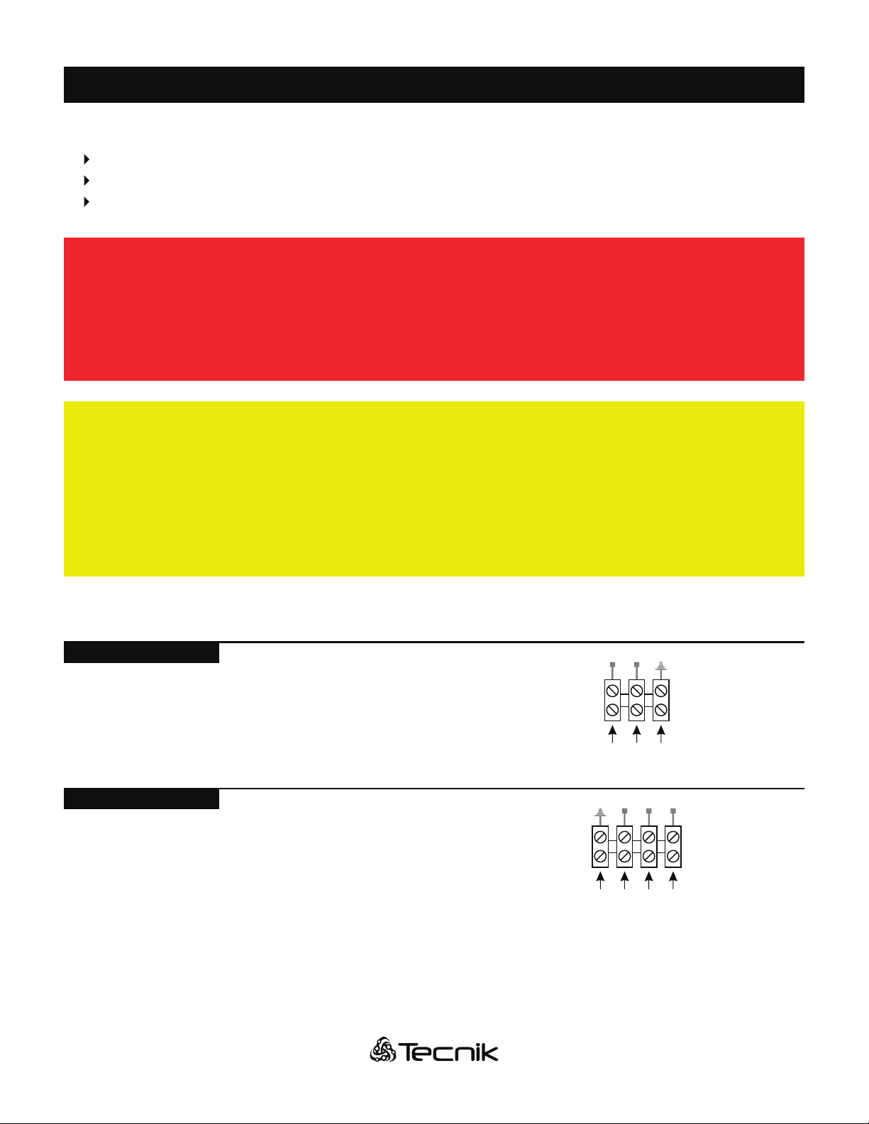
A.C. INPUT WIRING CONNECTION
GL1 L2 L3
G
L2L1
CF-MTL-42403 / 6003
CF-MTL-2401 / 42401
Connect the A.C. input ground wire (G) and line wires (L1, L2, L3)
on the four (4) position terminal.
Connect the A.C. input ground wire (G) and line wires (L1, L2)
on the three (3) position terminal.

www.tecnikchargers.comwww.tecnikchargers.comwww.tecnikchargers.com 888
CF-MTL-42401
208/240V 480V
Congure the A.C. input adjustment by changing the postion of the
three (3) metal jumpers on the six (6) position terminal block.
* Do not move any wires, only the metal jumpers
208/240V 480V
CF-MTL-42403
Congure the A.C. input adjustment by changing the postion of the
three (3) metal jumpers on the nine (9) position terminal block.
* Do not move any wires, only the metal jumpers
A.C. INPUT CONFIGURATION multi-input chargers only)
A.C. INPUT CALIBRATION
3 2 1 3 2 1 3 2 1
A B C
CF-MTL-42403
CF-MTL-6003
3
208/452V
575V
2
225/480V
600V
1
240/506V
610V
CF-MTL-2401 / 42401
CF-MTL-4803 / 6003
3 2 1 3 2 1
A A
Calibrate the input tuning according to A.C. source by changing the postion
of the three (3) wires (A, B, C) on the nine (9) position terminal strip.
Calibrate the input tuning according to A.C. source by changing the
postion of the two (2) wires on the six (6) position terminal strip (A, A).
CF-MTL-2401
CF-MTL-42401
3
220V
208/452V
2
240V
225/480V
1
250V
240/506V
CHARGER INSTALLATION
www.tecnikchargers.comwww.tecnikchargers.comwww.tecnikchargers.com 999
USING THE CHARGER
PROGRAMMING THE GASSING POINT (80%)
The proper programmation of the gassing point is important for the correct operation of the charger.
Only qualied personnel should modify these settings.
ATTENTION!
The possibility to program the gassing point may help the user to adjust the charging curve tothe requirements of the battery
during all its life. The default value is 2.40 Volt/cell.
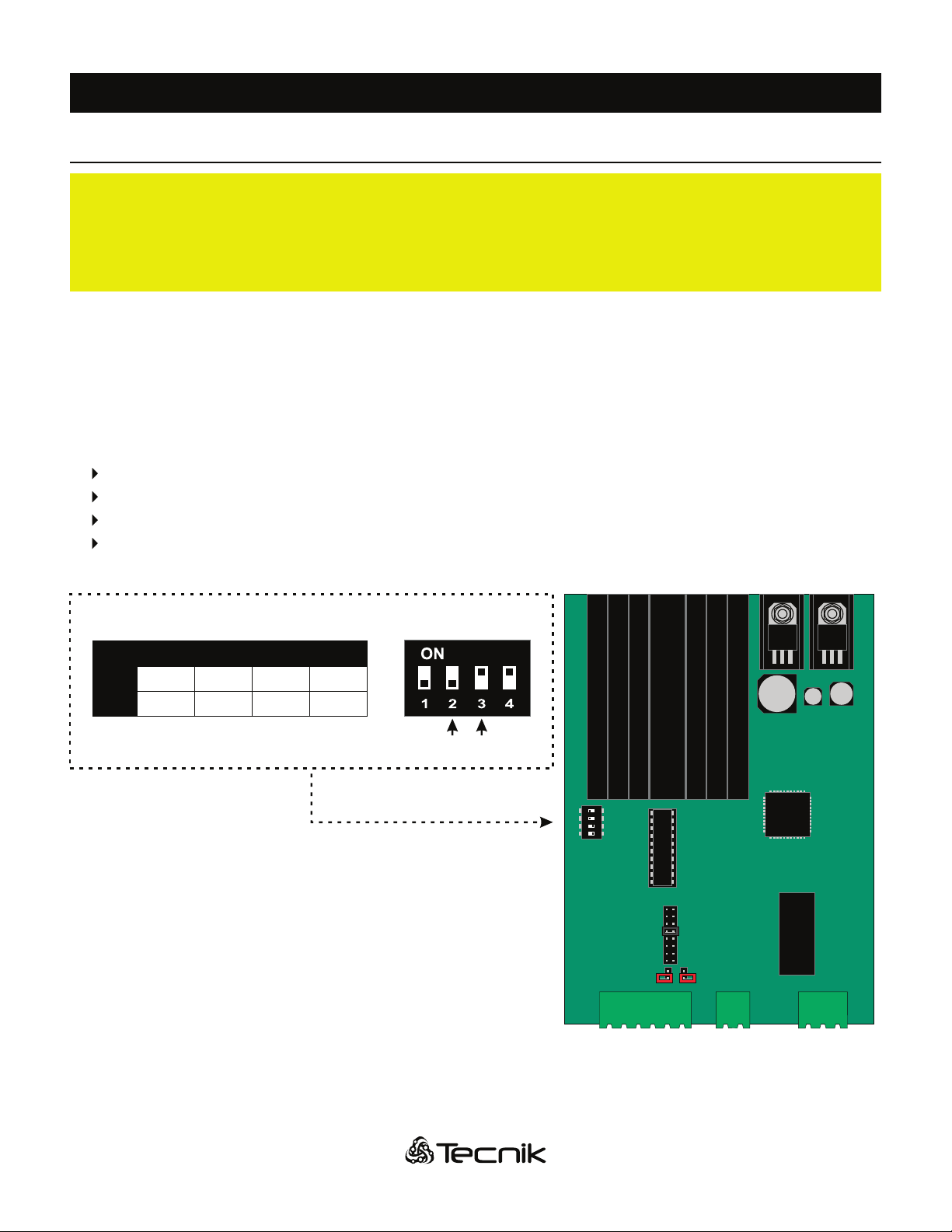
This value can be modied by changing positions on the 4 position dipswitch DS1 on the MTL control. Switches DS1-SW2
and DS1-SW3 are used for the programmation of the gassing point.
To modify the value, follow these steps:
Disconnect the charger from main A.C. supply and battery
Locate the dipswitches on the digital electronic board (see next picture)
Set the dipswitches according with the following table and picture
Connect the charger to main supply.
DS1
ON
1 2 3 4
JP3
24
36
40
48
72
80
96
JP2
JP1
DS1Gassing Point (V/cell)
SW2
SW3
2.35V
OFF
OFF
2.40V
OFF
ON
2.45V
ON
OFF
2.38V
ON
ON
SW2 SW3
* Default value in bold
When a battery will be connected to the charger,
the programmed gassing voltage will be shown
on the display during the startup sequence.
www.tecnikchargers.comwww.tecnikchargers.comwww.tecnikchargers.com 101010
BATTERY CONNECTION AND AUTOSTART
TRONIK chargers are programmed to execute a complete cycle of charge automatically, however it’s recommended
to survey the operations when the battery remains connected to the charger for more than 12 hours.
ATTENTION!
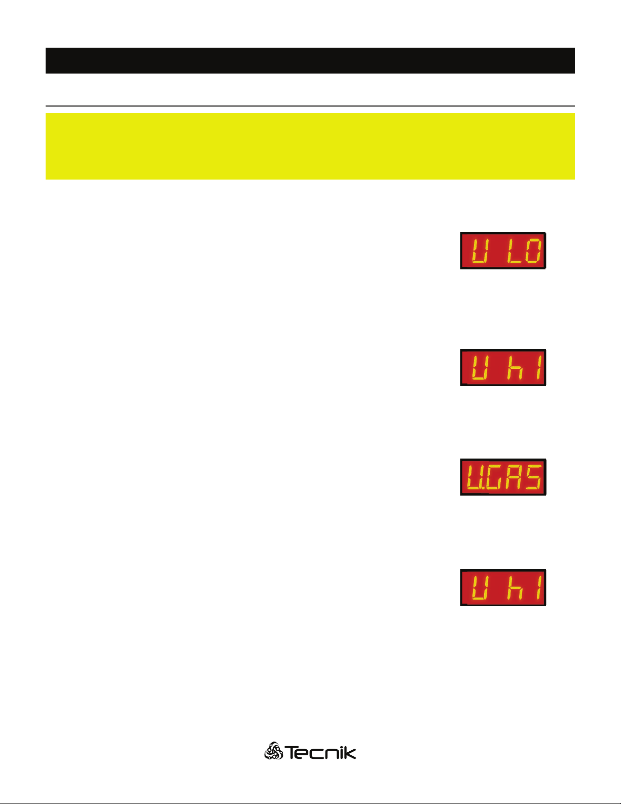
Connect the battery to the charger, using an adequate plug. When the battery is
correctly connected, the display turns on and shows the battery voltage. If the battery
voltage lower than the minimum threshold of 1,62 V/cell, the charger doesn't start,
and the display will show the error message “V LO” (voltage low):
If the battery voltage is higher than the maximum off charge threshold of 2,60 V/cell,
the charger doesn't start, and the display will show the (ashing) error message “V hI”
(voltage hi):
If the voltage of the battery is between the minimum and maximum thresholds, the
charger will wait for three 3 seconds before to start charging, while the display will
show the programmed gassing voltage:
If, during the charge, the voltage of the battery exceeds the maximum charging
threshold of 2,80 V/cell, the charger shuts down automatically, and the errore
message “V hI" (voltage high) will appear on the display.
USING THE CHARGER

www.tecnikchargers.comwww.tecnikchargers.comwww.tecnikchargers.com 111111
CHARGE OPERATION
Time is calculated and displayed like so: (Hours) . (Minutes/ by tens)
Example 1: 3h 40min is displayed as 3.4h
Example 2: 7h 30min is displayed as 7.3h
The charge current follows the Wa curve, as
described in the norm DIN 41774, while the
charge parameters continue to be shown on the
digital display.
The MTL control of the TRONIK charger has a digital display that supplies critical charging state information.
Durant the charge, the following parameters are displayed in sequence:
BATTERY VOLTAGE, in D.C. Volts/cell (U)
CHARGE CURRENT, in D.C. amps (A)
CHARGE TIME, in hours (h)
CAPACITY RETURNED, in Amp/hours - Ah (C)
Time
Voltage (V)
Current(A)
Nominal
Current
Voltage =
2.10V/cell
Voltage= 2.40V/cell
Current= 50% of Nominal
When the battery reaches the gassing voltage, the charge continues for one half of the time needed to reach the gassing
voltage, with a minimum total time of 30 minutes.
Examples:
If the battery reaches the gassing voltage in 1 minute, the nal charge will continue for 30 minutes.
If the battery reaches the gassing voltage in 5 hours, the nal charge will continue for 2 hours and 30 minutes.
If the battery reaches the gassing voltage in 10 hours, the nal charge will continue for 5 hours.
If the battery reaches the gassing voltage in 11h59m59s, the nal charge will continue for 5h 59m59s
(this is the maximum total time allowed before going to Emergency state).
These time limits enable the use of the charger with batteries of different capacities (depending on the time available for
the charge, from 8 to 18 hours), requiring no adjustments on the MTL control.
USING THE CHARGER
www.tecnikchargers.comwww.tecnikchargers.comwww.tecnikchargers.com 121212
SAFETY TIMER - EMERGENCY STOP
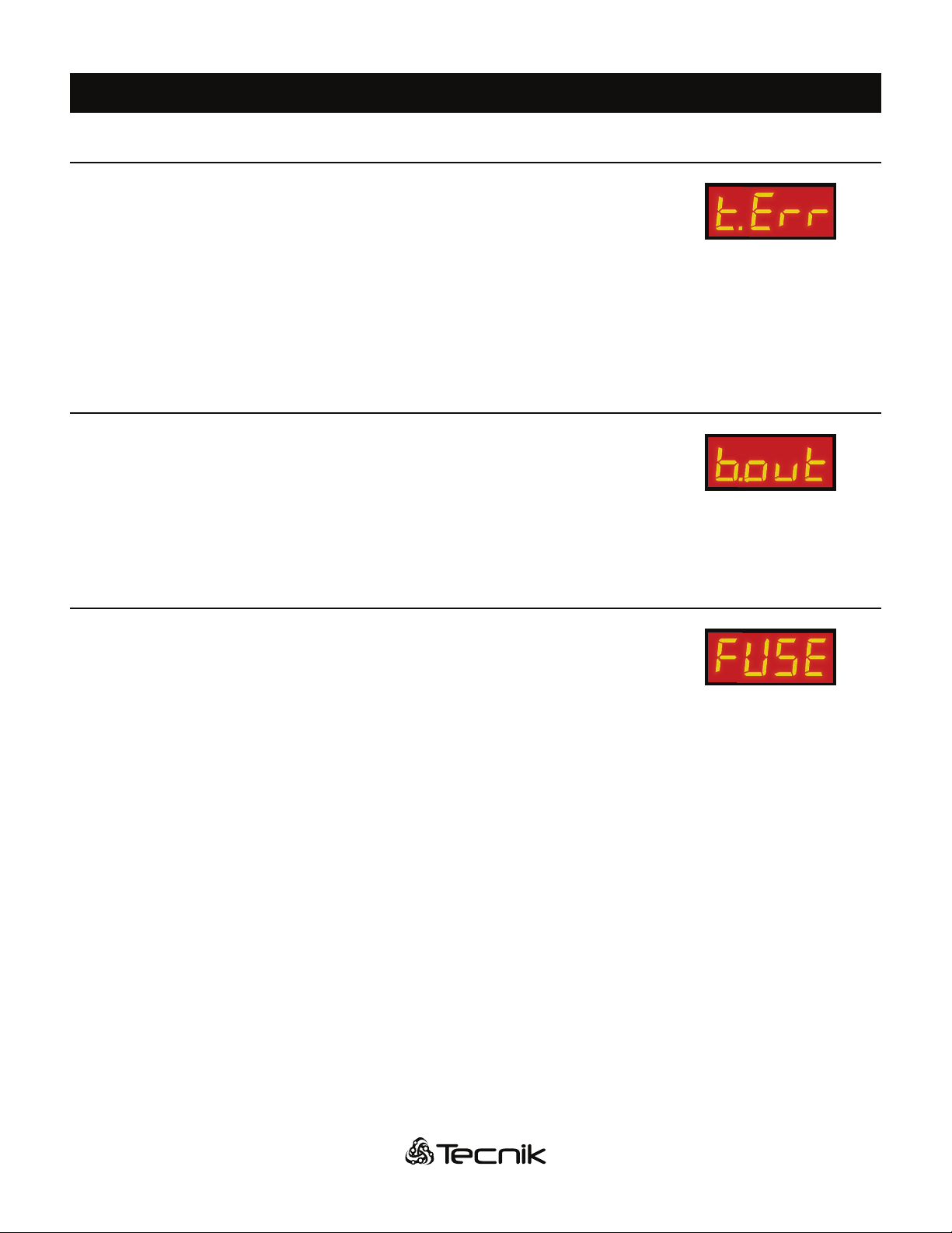
If the battery doesn't reach the gassing voltage in12 hours, the charge is terminated
by the safety timer, and the display shows the error message “t.Err” (time error).
If this error message appear, it's recommended to call TECNIK’s service dept. for a
complete check of the system.
The cause if this problem may be a wrong calibration of the input voltage: if the input
is set to a certain value (for example: 610 V) but the real voltage is lower (for example:
575 V), the charging current will be signicantly lower than the nominal value, thus
taking a longer time to reach the gassing voltage.
AUTOMATIC DATA SAVING
If, during the charge or equalization, one or more A.C. input black-outs occur, the
microprocessor automatically saves all the relevant charging cycle data. While the
input power is absent and if the battery remains connected to the charger, the display
will show the message “b.Out” (black out).
When the power reestablished, the charger will re-start automatically from the exact
point of interruption, and the charge will continue normally.
BLOWN D.C. FUSE DETECTION
If the D.C. output fuse is blown or absent, the display will show the message “FUSE”.
This message may appear also if the battery has been left discharged for long time,
causing the sulphation process on the plates or in case of a wrong A.C. input
conguration (ex: charger is congured for 480V and only 240V is feeded).
USING THE CHARGER
www.tecnikchargers.comwww.tecnikchargers.comwww.tecnikchargers.com 131313
AUTOMATIC CHARGE TERMINATION
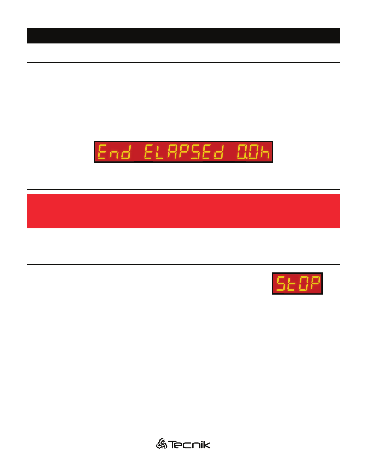
When the charge is complete, the charger shuts down, and the display shows the scrolling message “End ELAPSEd x.x h”.
The time indicated by the display is the time elapsed after the charge has been terminated. This indication is useful when
there are two or more forklift operated with FIFO (First In First Out) rotation: when the user picks up a forklift, he will always
chose the one with highest he time elapsed after charge termination.
The nal values of Voltage/cell, time of charge and capacity charged remain stored in memory.
If the red STOP pushbutton is pressed, the display will show these values in sequence.
AUTOMATIC SHUTDOWN ON BATTERY DISCONNECTION
NEVER disconnect the battery while it's being charged.
Disconnecting the battery while it's being charged is hazardous
DANGER!
If the battery is disconnected while the charge is in progress, the TRONIK charger switches off automatically.
MANUAL CHARGE TERMINATION
While the charge is in progress, it's possible to shut down the charger by pressing the
red button “MANUAL STOP” on the front panel. The display will show the message:
“StOP”.
The nal values of Voltage/cell, Time of charge and Capacity Charged remain stored
in memory. If the “MANUAL STOP” button is pressed again, these values will be
displayed in sequence. When the charge is terminated manually, the equalization
and refresh functions are automatically disabled.
USING THE CHARGER

www.tecnikchargers.comwww.tecnikchargers.comwww.tecnikchargers.com 141414
MANUAL EQUALIZE
The proper programming of the equalize & refresh modes is important for the correct operation of the charger.
Only qualied personnel should modify these settings.
ATTENTION!
The manual equalize function is intended for the users that prefer to manage the
equalization of the batteries personnally. It will extend the time of the charge cycle by 4
hours, and can be enabled by pushing the button located on the front panel during
the rst minutes of charge.
The display will show the message “Eq.On” (equalize on) to the display cycle of the
charge parameters, and the charge will proceed normally.
DAILY EQUALIZE
The dailty equalize function will extend all the charge cycles by 4 hours, and is useful to recover highly sulphated batteries.
Since it is a very intense equalize program and may tend to overcharge the battery, it's recommended to limit it’s use for short
periods and then to return to a normal equalize program. It's also recommended to survey the operation of the charger and
keep the temperaure of the battery under precise control while the daily equalize function is enabled.
It can be enabled by moving the dipswitch DS1-SW1 to the ON position (see the gure and picture on page 15).
The daily equalize function is disabled by default.
AUTO EQUALIZE AND REFRESH
The auto equalize and refresh mode is totally managed by the MTL control. Once the regular charge has been completed,
the charger will add 5 additional charge cycles of 30 minutes, with 14 hours and 30 minutes interval between each cycle.
This mode can be activated by moving the dipswitch DS1-SW4 of the MTL control (see the gure and picture on page 15).
Auto equalize and refresh is enabled by default.
During the time interval between each equalization cycle, the display will show the scrolling message “End ELAPSEd x.x h”
(end elapsed) and when the equalization cycles are in progress, the display will show the scrolling message “EqUAL
ChArGInG” (equalize charging), followed by the charging current.
USING THE CHARGER

www.tecnikchargers.comwww.tecnikchargers.comwww.tecnikchargers.com 151515
REFRESH OPERATION
If a battery is not used for a long time (example: seasonal works, holiday periods), it should be kept fully charged to avoid a
reduction of performance, therefore it's very important to charge the battery before leaving in standby for more than 72
hours. The self-discharge process makes it harder to keep a battery full over extended standby periods (weeks or months).
The refresh function is useful to keep the battery in optimal condition when it's in standby.
It is sufcient to leave the battery connected to the charger after the charge and the equalization is complete. The MTL
control’s microprocessor will keep the battery voltage under control and will activate the charger automatically if the voltage
drops below a predened minimum theshold.
While the battery is monitored by the charger, the display will show the scrolling message “VoLt COntrOL”:
If the voltage drops down below the minimum threshold, the charger will give an extra charge cycle to keep the battery in
optimal condition, and the display will show the scrolling message “rEFrESh”.
DS1
ON
1 2 3 4
JP3
24
36
40
48
72
80
96
JP2
JP1
DS1Adjustable equalizing parameters
SW1
SW4
ON
-
OFF
-
Daily
Equalize
-
OFF
SW1 SW4
* Default values in bold
-
ON
Auto equalize
& Refresh
USING THE CHARGER
Other manuals for TRONIK 812
1
This manual suits for next models
4
Table of contents
Other Tecnik Batteries Charger manuals


Popular Batteries Charger manuals by other brands

FUTABA
FUTABA ICS LF-01 instruction manual

electrify home
electrify home HomeStation EC2R040JPA10-00 Installation and operation manual

Hi-Tec
Hi-Tec multi cahrger X4 AC Plus instruction manual

Christie
Christie C2536D Installation and operating instructions

AEG
AEG BL18DP-LE Original instructions

Starkey
Starkey Mini Turbo Operation manual


